EP0699601A2 - Procédé et dispositif pour sécuriser la zone de travail d'un dispositif de vidange - Google Patents
Procédé et dispositif pour sécuriser la zone de travail d'un dispositif de vidange Download PDFInfo
- Publication number
- EP0699601A2 EP0699601A2 EP95113090A EP95113090A EP0699601A2 EP 0699601 A2 EP0699601 A2 EP 0699601A2 EP 95113090 A EP95113090 A EP 95113090A EP 95113090 A EP95113090 A EP 95113090A EP 0699601 A2 EP0699601 A2 EP 0699601A2
- Authority
- EP
- European Patent Office
- Prior art keywords
- emptying
- light barrier
- control device
- barrier
- barriers
- Prior art date
- Legal status (The legal status is an assumption and is not a legal conclusion. Google has not performed a legal analysis and makes no representation as to the accuracy of the status listed.)
- Granted
Links
- 238000000034 method Methods 0.000 title claims abstract description 48
- 230000004888 barrier function Effects 0.000 claims abstract description 122
- 238000012544 monitoring process Methods 0.000 claims abstract description 22
- 239000002699 waste material Substances 0.000 claims abstract description 11
- 238000012360 testing method Methods 0.000 claims description 17
- 238000011156 evaluation Methods 0.000 claims description 3
- 230000004913 activation Effects 0.000 claims description 2
- 238000013461 design Methods 0.000 description 2
- 238000010586 diagram Methods 0.000 description 2
- 230000007257 malfunction Effects 0.000 description 2
- 230000008033 biological extinction Effects 0.000 description 1
- 230000003111 delayed effect Effects 0.000 description 1
- 230000001419 dependent effect Effects 0.000 description 1
- 230000005670 electromagnetic radiation Effects 0.000 description 1
- 230000003287 optical effect Effects 0.000 description 1
- 230000005855 radiation Effects 0.000 description 1
- 238000010998 test method Methods 0.000 description 1
- 238000002604 ultrasonography Methods 0.000 description 1
Images

Classifications
-
- B—PERFORMING OPERATIONS; TRANSPORTING
- B65—CONVEYING; PACKING; STORING; HANDLING THIN OR FILAMENTARY MATERIAL
- B65F—GATHERING OR REMOVAL OF DOMESTIC OR LIKE REFUSE
- B65F3/00—Vehicles particularly adapted for collecting refuse
-
- G—PHYSICS
- G01—MEASURING; TESTING
- G01V—GEOPHYSICS; GRAVITATIONAL MEASUREMENTS; DETECTING MASSES OR OBJECTS; TAGS
- G01V8/00—Prospecting or detecting by optical means
- G01V8/10—Detecting, e.g. by using light barriers
- G01V8/12—Detecting, e.g. by using light barriers using one transmitter and one receiver
Definitions
- the invention relates to a method for securing the working area of emptying devices for emptying garbage containers into a collecting container, in which the lateral area next to the emptying device or devices is secured by means of barriers.
- the invention also relates to a corresponding device for securing the working area of emptying devices.
- a device for emptying containers in which the working area in the vicinity of the tilting device or lifting / tilting device can be secured by means of barriers acting on the control circuit.
- barriers are mounted on the side walls of the garbage truck or on the device so as to protect the operating personnel and uninvolved persons, for example temporary passers-by, about the horizontal axis.
- barriers which are swung up in the rest position and swung down in the working position and then assume an essentially horizontal position. In the working position, the barriers actuate a switching element that closes the control circuit for the emptying device. In the rest position of the barrier elements, this switch is released, which interrupts the control circuit.
- a safety barrier is known from DE 41 36 045 A1, which has at least a first and a second barrier part, the first barrier part being movable in the rest and securing position.
- all operating elements for the emptying device are attached to the first movable barrier part.
- the first movable barrier part interacts with the second barrier part in such a way that the operating elements for the emptying device are not accessible in the rest position of the first movable barrier part.
- the garbage workers bring them from behind to the garbage truck and attach them to the lowered emptying device or pick them up from the ground.
- this feeder area between the barriers is not secured during the emptying process.
- the object of the invention is therefore a method and a device for securing the working area of emptying devices, with which the feeder area is also secured, but the introduction and removal of the garbage containers is not hindered.
- This object is achieved with a method according to the features of claim 1.
- the device is the subject of claim 11.
- Advantageous embodiments of the invention are the subject of the dependent claims.
- the invention is based on the knowledge that the protection of the feeder area between the barriers should only be effective when the operator or the emptying devices can pose a hazard. This is usually the case if the waste bin (s) are already on the emptying device and are being emptied. It is therefore provided according to the invention that the feeder area between the barriers is secured at least during a period of the emptying process by means of at least one light barrier which prevents or interrupts the emptying process if interrupted.
- This time period which is referred to as the monitoring phase, can be shorter or longer than the emptying process, which can depend on the emptying devices used in each case, which can be designed as automatic, semi-automatic or purely manual emptying devices.
- the applicable safety regulations must also be taken into account.
- the monitoring phase can preferably be ended after the start of the emptying process and, if appropriate, also before the emptying process has been completed, if the container and the emptying device for the operating personnel are each already at a safe level. Depending on the design of the emptying device, it must be ensured that after the refuse container has been brought up, the operating personnel have sufficient time to leave the working area of the emptying device without interrupting the light barrier that has already been activated.
- the early termination of the monitoring phase offers the advantage of allowing the operating personnel to enter the work area earlier.
- the entire working area of the emptying device is secured from all sides at least during a period of the emptying process, so that the operating personnel and other persons are not endangered during this process.
- the light barrier is preferably only activated when the emptying device has reached a predetermined lifting height. It can also be provided that the light barrier is only activated when the waste container is locked on the emptying device.
- the light barrier is checked after activation, the test phase preferably being carried out before and / or after the monitoring phase.
- the transmitter of the light barrier is advantageously switched off briefly after the initial switch-on and the signal level of the receiver is evaluated. If the light barrier is working properly, the receiver must not deliver a signal. If this is not the case, the emptying process is either not started at all or an emptying process that may already be in progress is terminated.
- the evaluation of the receiver level is not started when the transmitter is switched off, but rather with a time delay. This takes into account the inertia of the transmitter, i.e. the delayed extinction of the light signal. This means, that the evaluation phase only begins after the transmitter, ie the light source, has completely gone out.
- the device for securing the working area of emptying devices provides that at least one light barrier is arranged at the free end of the barriers, the transmitter being attached to one barrier and the receiver opposite to the other barrier.
- the light barrier is connected to a control device which is designed to activate the light barrier during a period of the emptying process and to interrupt or prevent the emptying process when the light barrier is interrupted.
- a light barrier is understood to mean a device which can work not only with visible light but also, for example, with infrared radiation or ultrasound. Any electromagnetic radiation that is safe for the operating personnel and can be interrupted by people or objects is suitable.
- test devices which are connected between the transmitter and receiver of the light barrier and which use the so-called self-test method to check the light barrier do not guarantee that all components of the light barrier work properly. Faults in the area of the light barrier can be determined, but not faults of the test device itself or a fault between the test device and the control of the emptying device. It has therefore proven to be advantageous to connect the transmitter and receiver of the light barrier directly to the control device of the emptying device. A pulse goes from this control device to the transmitter of the light barrier, the light signal goes from the transmitter to the receiver and from the receiver in turn to the control device.
- the control device is preferably designed such that the light barrier is only activated when the emptying device has reached a predetermined lifting height at the beginning of the emptying process.
- at least one first position sensor which is connected to the control device, can be assigned to the emptying device in the predetermined lifting height. If the emptying device moves upward as part of the emptying process, this position sensor is switched, which then sends a corresponding signal to the control device, which in turn then activates the light barrier.
- control device can also be designed such that it only activates the light barrier when the waste container is locked to the emptying device.
- a corresponding sensor is provided on the locking device and is connected to the control device.
- control device In order to monitor the functionality of the light barrier with great reliability and to be able to recognize malfunctions immediately, the control device is designed to check the light barrier, the control device being designed to carry out the previously described method features.
- the monitoring is preferably switched off again when the first position sensor is reached.
- at least one second position sensor can be assigned to the emptying device at a different height, which is also connected to the control device.
- the second position sensor is acted on, which leads to the switching off of the light barrier.
- test phase which can be carried out before and / or after the monitoring phase, is preferably in an area of the path of the emptying device which does not indicate any danger to the operating personnel or uninvolved third parties.
- the control device is preferably connected to a display device which visually or acoustically displays the active or inactive function of the light barrier to the operating personnel.
- Safety can be further improved in that the barriers are arranged so as to be movable about a vertical axis and in that the light barrier is designed such that the light barrier is interrupted when at least one barrier is hit. This can be achieved, for example, by making the receiver surface as small as possible, so that the light beam migrates out of the sensitive area of the receiver even when one of the barriers is lightly impacted, and an interruption of the light barrier is thus detected.
- the operating personnel may be within this delimited area without the light barrier arranged at the free ends of the barriers is proven.
- this light barrier or an additional light barrier in the area where the operating personnel are at the barriers.
- the device can be combined with differently designed barriers.
- the barriers can be any mechanical elements, such as swiveling barriers or rigidly attached deflectors.
- FIG. 1 shows a garbage truck 1 with an emptying device 2, which is guided on rails 3, 4 at the rear of the garbage truck 1 and empties the garbage container (not shown) into the filling opening 5 of the collecting container of the garbage truck.
- the working area of the emptying device 2 is secured with lateral barriers in the manner of barriers 6, 7 against lateral access.
- the barriers 6, 7 are provided at their free ends 16, 17 with a light barrier 18, the transmitter 8 of which is arranged on the barrier 6 and the receiver 9 of which is arranged on the barrier 7.
- at least one further light barrier can optionally be arranged on the barriers 6, 7 between the light barrier 18 and the emptying device 2, to prove persons in the work area of the emptying device during the emptying process.
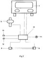
- the transmitter 8 and the receiver 9 are electrically connected to the control device 10 of the emptying device, which is arranged at a protected location on the emptying device or on the vehicle.
- the control device 10 is connected to a display device 11 in the central region of the rear of the vehicle, which displays the active or inactive function of the light barrier optically or acoustically.
- a first position sensor 12 and a second position sensor 15, which are also connected to the control device 10, are arranged to the side of the rails 3 and 4.
- the emptying device 2 is started up, the first position sensor 12 is switched at a predetermined height, which then sends a corresponding signal to the control device 10, which then activates the light barrier 18.
- the second position sensor 15 is inactive.
- the emptying device 2 moves down on the rails 3, 4 and actuates the second position sensor 15 at a different predetermined height, which emits a corresponding signal to the control device 10, which then switches off the light barrier 18 , so that the operating personnel can enter the work area of the emptying device and remove the emptied waste container.
- the barriers 6, 7 can be arranged to be movable about a vertical axis, so that even when one of the barriers 6, 7 is hit, the light beam 14 migrates out of the reception area of the receiver 9, whereupon the control device 10 detects an interruption in the light barrier will what to interrupt the Emptying process.
- emptying device 2 shown in FIG. 1 other emptying devices such as tilting or lifting-tilting devices can also be provided.
- FIG. 1 A schematic representation of the circuit is shown in FIG.
- the garbage worker gives the start command to the control device 10 by actuating an electrical button, which then opens a solenoid valve 13 in order to pressurize the drive motors, preferably piston / cylinder units.
- the lifting process begins and when the emptying device reaches the position sensor 12, the control unit 10 activates the transmitter 8 of the light barrier, which in turn activates the receiver 9 by means of its light source. This gives a signal to the control device 10 and thus indicates that the light barrier has been activated.
- a self-test takes place during the test phase in that the transmitter 8 is switched off for fractions of a second.
- the receiver 9 must then also inevitably switch off and signal the inoperability to the control device 10.
- the control device 10 registers the switching off of the receiver 9 and thus the safe functioning of the light barrier.
- the transmitter 8 is reactivated immediately after the end of the test phase, and the light barrier 18 goes into the monitoring phase for the further emptying process, which is only switched off again when the waste container is lowered and the second position sensor 15 is reached.
- the garbage collector can then remove the deposited container from the emptying device. If the light barrier is interrupted during the monitoring phase, it has to Consequence that the device is stopped immediately.
- the self-test of the light barrier 18 described above takes place before and / or after each emptying cycle in the lower safe area of the emptying device.
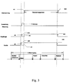
- the time sequence of the individual phases is shown schematically in FIG.
- the emptying process is divided into individual sequences, which consist of first picking up the container, lifting it, tipping it, lowering it and finally putting it down.
- a monitoring phase is provided which is shorter than the emptying process. In the example shown here, the monitoring phase only starts when the waste container has already been raised. The monitoring phase ends shortly before the emptied container is set down.
- This monitoring phase is preceded by a test phase.
- the transmitter of the light barrier is first switched on, whereupon the receiver sends a signal to the control device with a time delay.
- the test phase begins in the control device, it being first determined on the basis of the receiver signal whether the light barrier has been activated. If this is the case, the transmitter is immediately switched off for a fraction of a second, with the result that the receiver no longer reports a signal.
- the signal level of the receiver is evaluated within the test phase with a time delay before the transmitter is switched off. If the light barrier is working properly, no output signal from the receiver is detected, whereupon the test phase is ended. When the test phase ends, the transmitter is switched on again and the monitoring phase begins.
Landscapes
- Mechanical Engineering (AREA)
- Physics & Mathematics (AREA)
- Life Sciences & Earth Sciences (AREA)
- General Life Sciences & Earth Sciences (AREA)
- General Physics & Mathematics (AREA)
- Geophysics (AREA)
- Engineering & Computer Science (AREA)
- Refuse-Collection Vehicles (AREA)
- Refuse Collection And Transfer (AREA)
- Electrical Discharge Machining, Electrochemical Machining, And Combined Machining (AREA)
- Power Steering Mechanism (AREA)
- Control Of Motors That Do Not Use Commutators (AREA)
- Spinning Or Twisting Of Yarns (AREA)
- Operating, Guiding And Securing Of Roll- Type Closing Members (AREA)
- Laser Beam Processing (AREA)
- Diaphragms For Electromechanical Transducers (AREA)
Applications Claiming Priority (2)
| Application Number | Priority Date | Filing Date | Title |
|---|---|---|---|
| DE4430833A DE4430833C1 (de) | 1994-08-31 | 1994-08-31 | Verfahren und Vorrichtung zum Absichern des Arbeitsbereichs von Entleereinrichtungen |
| DE4430833 | 1994-08-31 |
Publications (3)
| Publication Number | Publication Date |
|---|---|
| EP0699601A2 true EP0699601A2 (fr) | 1996-03-06 |
| EP0699601A3 EP0699601A3 (fr) | 1996-06-05 |
| EP0699601B1 EP0699601B1 (fr) | 2001-05-23 |
Family
ID=6526966
Family Applications (1)
| Application Number | Title | Priority Date | Filing Date |
|---|---|---|---|
| EP95113090A Expired - Lifetime EP0699601B1 (fr) | 1994-08-31 | 1995-08-21 | Procédé et dispositif pour sécuriser la zone de travail d'un dispositif de vidange |
Country Status (11)
| Country | Link |
|---|---|
| EP (1) | EP0699601B1 (fr) |
| AT (1) | ATE201373T1 (fr) |
| CZ (1) | CZ289334B6 (fr) |
| DE (2) | DE4430833C1 (fr) |
| DK (1) | DK0699601T3 (fr) |
| ES (1) | ES2158019T3 (fr) |
| GR (1) | GR3035986T3 (fr) |
| HU (1) | HU219745B (fr) |
| PL (1) | PL177881B1 (fr) |
| PT (1) | PT699601E (fr) |
| SK (1) | SK283328B6 (fr) |
Cited By (3)
| Publication number | Priority date | Publication date | Assignee | Title |
|---|---|---|---|---|
| NL1003535C2 (nl) * | 1996-07-08 | 1998-01-12 | Geesink Bv | Afvalinzamelvoertuig voorzien van beveiligingsmiddelen. |
| US9718107B2 (en) | 2013-05-30 | 2017-08-01 | Hyundai Steel Company | Belt replacement device |
| WO2020058205A1 (fr) * | 2018-09-17 | 2020-03-26 | Gummi-Welz Gmbh & Co. Kg Gummi-Kunststofftechnik-Schaumstoffe | Dispositif de surveillance d'un espace de mouvement et procédé de surveillance d'un espace de mouvement |
Families Citing this family (7)
| Publication number | Priority date | Publication date | Assignee | Title |
|---|---|---|---|---|
| DE29712512U1 (de) * | 1997-07-15 | 1997-09-11 | Zöller-Kipper GmbH, 55130 Mainz | Vorrichtung zum Absichern des Arbeitsbereiches von Entleereinrichtungen |
| NL1007733C2 (nl) * | 1997-12-08 | 1999-06-09 | Geesink Bv | Afvalinzamelvoertuig voorzien van beveiligingsmiddelen. |
| NL1007748C2 (nl) * | 1997-12-09 | 1999-06-10 | Geesink Bv | Afvalinzamelvoertuig voor het legen van vuilcontainers. |
| DE102004036363B4 (de) * | 2004-07-22 | 2006-11-23 | Zöller-Kipper GmbH | Verfahren und Vorrichtung zur Absicherung des Arbeitsbereiches von Entleervorrichtungen |
| EP2113742B2 (fr) † | 2008-04-30 | 2019-01-02 | Baumer Electric AG | Dispositif de mesure doté d'un balayage à deux canaux |
| NL2008407C2 (nl) * | 2012-03-05 | 2013-09-09 | Terberg Machines | Bewakingsinrichting voor het bewaken van een werkgebied, een beladingsysteem en voertuig voorzien daarvan, en werkwijze daarvoor. |
| DE102013223840A1 (de) | 2013-11-21 | 2015-05-21 | Zöller-Kipper GmbH | Sicherheitsvorrichtung |
Citations (2)
| Publication number | Priority date | Publication date | Assignee | Title |
|---|---|---|---|---|
| DE3405997A1 (de) | 1984-02-20 | 1985-08-22 | Zöller-Kipper GmbH, 6500 Mainz | Vorrichtung zum entleeren von behaeltern, insbesondere muellbehaeltern |
| DE4136045A1 (de) | 1991-11-01 | 1993-05-06 | Zoeller-Kipper Gmbh, 6500 Mainz, De | Sicherheitsschranke |
Family Cites Families (8)
| Publication number | Priority date | Publication date | Assignee | Title |
|---|---|---|---|---|
| CH384078A (de) * | 1961-02-08 | 1964-11-15 | Zellweger Uster Ag | Verfahren und Vorrichtung zur Bereitschaftskontrolle von Lichtschranken |
| DE1269923B (de) * | 1963-08-29 | 1968-06-06 | Lothar Franke | Lichtgitterschranke mit mehreren Strahlen |
| US3970846A (en) * | 1973-10-29 | 1976-07-20 | Xenex Corporation | Presence detecting system with self-checking |
| US3942601A (en) * | 1974-04-18 | 1976-03-09 | Sargent Industries, Inc. | Refuse collection apparatus with personnel protection means |
| US4309696A (en) * | 1978-06-26 | 1982-01-05 | Kabushiki Kaisha Komatsu Seisakusho | Trouble detecting unit in an optical security device |
| US4266124A (en) * | 1979-08-10 | 1981-05-05 | Data Instruments, Inc. | Photoelectric object detector system |
| DE8707192U1 (de) * | 1987-05-19 | 1987-07-09 | AHS-Prüftechnik A. u. H. Schneider GmbH & Co KG, 2870 Delmenhorst | Vorrichtung zum Absichern einer Kfz-Arbeitsgrube |
| DE4128955C1 (fr) * | 1991-08-30 | 1992-11-05 | Zoeller Kipper |
-
1994
- 1994-08-31 DE DE4430833A patent/DE4430833C1/de not_active Expired - Lifetime
-
1995
- 1995-08-09 HU HU9502353A patent/HU219745B/hu not_active IP Right Cessation
- 1995-08-21 DK DK95113090T patent/DK0699601T3/da active
- 1995-08-21 DE DE59509278T patent/DE59509278D1/de not_active Expired - Lifetime
- 1995-08-21 PT PT95113090T patent/PT699601E/pt unknown
- 1995-08-21 EP EP95113090A patent/EP0699601B1/fr not_active Expired - Lifetime
- 1995-08-21 ES ES95113090T patent/ES2158019T3/es not_active Expired - Lifetime
- 1995-08-21 AT AT95113090T patent/ATE201373T1/de active
- 1995-08-25 SK SK1057-95A patent/SK283328B6/sk unknown
- 1995-08-29 CZ CZ19952204A patent/CZ289334B6/cs not_active IP Right Cessation
- 1995-08-30 PL PL95310229A patent/PL177881B1/pl not_active IP Right Cessation
-
2001
- 2001-05-31 GR GR20010400837T patent/GR3035986T3/el unknown
Patent Citations (2)
| Publication number | Priority date | Publication date | Assignee | Title |
|---|---|---|---|---|
| DE3405997A1 (de) | 1984-02-20 | 1985-08-22 | Zöller-Kipper GmbH, 6500 Mainz | Vorrichtung zum entleeren von behaeltern, insbesondere muellbehaeltern |
| DE4136045A1 (de) | 1991-11-01 | 1993-05-06 | Zoeller-Kipper Gmbh, 6500 Mainz, De | Sicherheitsschranke |
Cited By (3)
| Publication number | Priority date | Publication date | Assignee | Title |
|---|---|---|---|---|
| NL1003535C2 (nl) * | 1996-07-08 | 1998-01-12 | Geesink Bv | Afvalinzamelvoertuig voorzien van beveiligingsmiddelen. |
| US9718107B2 (en) | 2013-05-30 | 2017-08-01 | Hyundai Steel Company | Belt replacement device |
| WO2020058205A1 (fr) * | 2018-09-17 | 2020-03-26 | Gummi-Welz Gmbh & Co. Kg Gummi-Kunststofftechnik-Schaumstoffe | Dispositif de surveillance d'un espace de mouvement et procédé de surveillance d'un espace de mouvement |
Also Published As
| Publication number | Publication date |
|---|---|
| DE59509278D1 (de) | 2001-06-28 |
| EP0699601B1 (fr) | 2001-05-23 |
| CZ289334B6 (cs) | 2002-01-16 |
| DE4430833C1 (de) | 1995-11-23 |
| PT699601E (pt) | 2001-11-30 |
| PL310229A1 (en) | 1996-03-04 |
| PL177881B1 (pl) | 2000-01-31 |
| SK105795A3 (en) | 1996-05-08 |
| HU9502353D0 (en) | 1995-09-28 |
| GR3035986T3 (en) | 2001-08-31 |
| CZ220495A3 (en) | 1996-03-13 |
| EP0699601A3 (fr) | 1996-06-05 |
| HUT72236A (en) | 1996-04-29 |
| SK283328B6 (sk) | 2003-06-03 |
| ES2158019T3 (es) | 2001-09-01 |
| DK0699601T3 (da) | 2001-07-30 |
| ATE201373T1 (de) | 2001-06-15 |
| HU219745B (hu) | 2001-07-30 |
Similar Documents
| Publication | Publication Date | Title |
|---|---|---|
| EP0156445B1 (fr) | Dispositif pour le déchargement de récipients, en particulier de récipients à ordures | |
| EP0047812B1 (fr) | Procédé de commande électronique et de surveillance du cycle d'ouverture et de fermeture des accessoires à commande électrique, par exemple lève-glaces et toits ouvrants électriques, en particulier pour automobiles, et circuit électrique correspondant | |
| EP0278307B1 (fr) | Dispositif de protection pour un dispositif de culbutage ou pour un dispositif de levage-culbutage | |
| DE3032584C2 (de) | Vorrichtung zur Überwachung und Sicherung von begehbaren Gefahrenbereichen an kraftgetriebenen Textilmaschinen | |
| EP0391225B1 (fr) | Circuit de sécurité avec contacteurs pour dispositifs de renversement et/ou de levage | |
| DE4233810C2 (de) | Überwachungsvorrichtung bei Arbeitsmaschinen | |
| DE4430833C1 (de) | Verfahren und Vorrichtung zum Absichern des Arbeitsbereichs von Entleereinrichtungen | |
| CH677801A5 (fr) | ||
| DE19701645C2 (de) | Vorrichtung zur Handhabung eines mittels Bogen gebildeten Stapels an einer Druckmaschine | |
| DE2440611A1 (de) | Automatische werkstattanlage | |
| DE4128955C1 (fr) | ||
| EP2799384A1 (fr) | Porte motorisée dotée d'un dispositif de sécurité | |
| DE3205166A1 (de) | Zentralverriegelungsanlage | |
| DE102019113507A1 (de) | Sammelbehälter, Müllfahrzeug und Verfahren zur Überwachung eines Beschickungsbereichs | |
| EP0540981B1 (fr) | Barrière de sécurité | |
| EP0728683B1 (fr) | Dispositif pour basculer des différents récipients à ordures d'une position de préhension en une position de décharge | |
| EP0569927A2 (fr) | Marchepied pour véhicule de ramassage d'ordures | |
| DE3722184C2 (de) | Vorrichtung zum entleeren von behaeltern | |
| DE10354158B4 (de) | Vorrichtung zum Aufstellen einer Fahrzeug-Tür, insbesondere einer Kfz-Fronthaube, in einer Unfallsituation | |
| DE29903065U1 (de) | Entleervorrichtung | |
| DE102005023154A1 (de) | Müllbehälter-Lifter mit Hinterraum-Überwachung | |
| CH639788A5 (en) | Safety device for prompt de-activation or switchover of an installation when a dangerous situation occurs | |
| DE2827863A1 (de) | Optisches sicherheitssystem | |
| DE69902605T2 (de) | Ladevorrichtung für eine mit einer Sicherungseinrichtung versehenen Müllsammelvorrichtung | |
| EP1342677A1 (fr) | Benne à ordures ménagères |
Legal Events
| Date | Code | Title | Description |
|---|---|---|---|
| PUAI | Public reference made under article 153(3) epc to a published international application that has entered the european phase |
Free format text: ORIGINAL CODE: 0009012 |
|
| AK | Designated contracting states |
Kind code of ref document: A2 Designated state(s): AT BE CH DE DK ES FR GB GR IE IT LI LU MC NL PT SE |
|
| PUAL | Search report despatched |
Free format text: ORIGINAL CODE: 0009013 |
|
| AK | Designated contracting states |
Kind code of ref document: A3 Designated state(s): AT BE CH DE DK ES FR GB GR IE IT LI LU MC NL PT SE |
|
| 17P | Request for examination filed |
Effective date: 19960821 |
|
| 17Q | First examination report despatched |
Effective date: 19971230 |
|
| GRAG | Despatch of communication of intention to grant |
Free format text: ORIGINAL CODE: EPIDOS AGRA |
|
| GRAG | Despatch of communication of intention to grant |
Free format text: ORIGINAL CODE: EPIDOS AGRA |
|
| GRAH | Despatch of communication of intention to grant a patent |
Free format text: ORIGINAL CODE: EPIDOS IGRA |
|
| GRAH | Despatch of communication of intention to grant a patent |
Free format text: ORIGINAL CODE: EPIDOS IGRA |
|
| GRAA | (expected) grant |
Free format text: ORIGINAL CODE: 0009210 |
|
| AK | Designated contracting states |
Kind code of ref document: B1 Designated state(s): AT BE CH DE DK ES FR GB GR IE IT LI LU MC NL PT SE |
|
| REF | Corresponds to: |
Ref document number: 201373 Country of ref document: AT Date of ref document: 20010615 Kind code of ref document: T |
|
| REG | Reference to a national code |
Ref country code: CH Ref legal event code: EP |
|
| REF | Corresponds to: |
Ref document number: 59509278 Country of ref document: DE Date of ref document: 20010628 |
|
| REG | Reference to a national code |
Ref country code: IE Ref legal event code: FG4D Free format text: GERMAN |
|
| ITF | It: translation for a ep patent filed | ||
| REG | Reference to a national code |
Ref country code: DK Ref legal event code: T3 |
|
| REG | Reference to a national code |
Ref country code: CH Ref legal event code: NV Representative=s name: R. A. EGLI & CO. PATENTANWAELTE |
|
| REG | Reference to a national code |
Ref country code: ES Ref legal event code: FG2A Ref document number: 2158019 Country of ref document: ES Kind code of ref document: T3 |
|
| GBT | Gb: translation of ep patent filed (gb section 77(6)(a)/1977) |
Effective date: 20010814 |
|
| ET | Fr: translation filed | ||
| REG | Reference to a national code |
Ref country code: PT Ref legal event code: SC4A Free format text: AVAILABILITY OF NATIONAL TRANSLATION Effective date: 20010822 |
|
| REG | Reference to a national code |
Ref country code: GB Ref legal event code: IF02 |
|
| PLBE | No opposition filed within time limit |
Free format text: ORIGINAL CODE: 0009261 |
|
| STAA | Information on the status of an ep patent application or granted ep patent |
Free format text: STATUS: NO OPPOSITION FILED WITHIN TIME LIMIT |
|
| 26N | No opposition filed | ||
| PGFP | Annual fee paid to national office [announced via postgrant information from national office to epo] |
Ref country code: DK Payment date: 20110824 Year of fee payment: 17 Ref country code: CH Payment date: 20110824 Year of fee payment: 17 |
|
| REG | Reference to a national code |
Ref country code: DE Ref legal event code: R082 Ref document number: 59509278 Country of ref document: DE Representative=s name: MEHLER ACHLER PATENTANWAELTE, DE |
|
| PGFP | Annual fee paid to national office [announced via postgrant information from national office to epo] |
Ref country code: LU Payment date: 20120824 Year of fee payment: 18 |
|
| PGFP | Annual fee paid to national office [announced via postgrant information from national office to epo] |
Ref country code: IE Payment date: 20120821 Year of fee payment: 18 Ref country code: SE Payment date: 20120823 Year of fee payment: 18 Ref country code: GB Payment date: 20120823 Year of fee payment: 18 Ref country code: MC Payment date: 20120823 Year of fee payment: 18 |
|
| PGFP | Annual fee paid to national office [announced via postgrant information from national office to epo] |
Ref country code: GR Payment date: 20120821 Year of fee payment: 18 |
|
| PGFP | Annual fee paid to national office [announced via postgrant information from national office to epo] |
Ref country code: ES Payment date: 20120824 Year of fee payment: 18 Ref country code: FR Payment date: 20120831 Year of fee payment: 18 Ref country code: IT Payment date: 20120824 Year of fee payment: 18 Ref country code: BE Payment date: 20120831 Year of fee payment: 18 |
|
| PGFP | Annual fee paid to national office [announced via postgrant information from national office to epo] |
Ref country code: PT Payment date: 20120221 Year of fee payment: 18 Ref country code: NL Payment date: 20120824 Year of fee payment: 18 Ref country code: DE Payment date: 20121024 Year of fee payment: 18 |
|
| PGFP | Annual fee paid to national office [announced via postgrant information from national office to epo] |
Ref country code: AT Payment date: 20120822 Year of fee payment: 18 |
|
| BERE | Be: lapsed |
Owner name: *ZOLLER-KIPPER G.M.B.H. Effective date: 20130831 |
|
| REG | Reference to a national code |
Ref country code: PT Ref legal event code: MM4A Free format text: LAPSE DUE TO NON-PAYMENT OF FEES Effective date: 20140221 |
|
| REG | Reference to a national code |
Ref country code: NL Ref legal event code: V1 Effective date: 20140301 |
|
| REG | Reference to a national code |
Ref country code: CH Ref legal event code: PL Ref country code: DK Ref legal event code: EBP Effective date: 20130831 |
|
| REG | Reference to a national code |
Ref country code: SE Ref legal event code: EUG |
|
| REG | Reference to a national code |
Ref country code: AT Ref legal event code: MM01 Ref document number: 201373 Country of ref document: AT Kind code of ref document: T Effective date: 20130821 |
|
| GBPC | Gb: european patent ceased through non-payment of renewal fee |
Effective date: 20130821 |
|
| REG | Reference to a national code |
Ref country code: GR Ref legal event code: ML Ref document number: 20010400837 Country of ref document: GR Effective date: 20140305 |
|
| PG25 | Lapsed in a contracting state [announced via postgrant information from national office to epo] |
Ref country code: CH Free format text: LAPSE BECAUSE OF NON-PAYMENT OF DUE FEES Effective date: 20130831 Ref country code: DE Free format text: LAPSE BECAUSE OF NON-PAYMENT OF DUE FEES Effective date: 20140301 Ref country code: SE Free format text: LAPSE BECAUSE OF NON-PAYMENT OF DUE FEES Effective date: 20130822 Ref country code: NL Free format text: LAPSE BECAUSE OF NON-PAYMENT OF DUE FEES Effective date: 20140301 Ref country code: MC Free format text: LAPSE BECAUSE OF NON-PAYMENT OF DUE FEES Effective date: 20130902 Ref country code: LI Free format text: LAPSE BECAUSE OF NON-PAYMENT OF DUE FEES Effective date: 20130831 |
|
| REG | Reference to a national code |
Ref country code: IE Ref legal event code: MM4A |
|
| REG | Reference to a national code |
Ref country code: FR Ref legal event code: ST Effective date: 20140430 |
|
| PG25 | Lapsed in a contracting state [announced via postgrant information from national office to epo] |
Ref country code: GR Free format text: LAPSE BECAUSE OF NON-PAYMENT OF DUE FEES Effective date: 20140305 Ref country code: BE Free format text: LAPSE BECAUSE OF NON-PAYMENT OF DUE FEES Effective date: 20130831 Ref country code: IT Free format text: LAPSE BECAUSE OF NON-PAYMENT OF DUE FEES Effective date: 20130821 Ref country code: AT Free format text: LAPSE BECAUSE OF NON-PAYMENT OF DUE FEES Effective date: 20130821 |
|
| REG | Reference to a national code |
Ref country code: DE Ref legal event code: R119 Ref document number: 59509278 Country of ref document: DE Effective date: 20140301 |
|
| PG25 | Lapsed in a contracting state [announced via postgrant information from national office to epo] |
Ref country code: PT Free format text: LAPSE BECAUSE OF NON-PAYMENT OF DUE FEES Effective date: 20140221 |
|
| PG25 | Lapsed in a contracting state [announced via postgrant information from national office to epo] |
Ref country code: IE Free format text: LAPSE BECAUSE OF NON-PAYMENT OF DUE FEES Effective date: 20130821 Ref country code: GB Free format text: LAPSE BECAUSE OF NON-PAYMENT OF DUE FEES Effective date: 20130821 |
|
| PG25 | Lapsed in a contracting state [announced via postgrant information from national office to epo] |
Ref country code: FR Free format text: LAPSE BECAUSE OF NON-PAYMENT OF DUE FEES Effective date: 20130902 |
|
| REG | Reference to a national code |
Ref country code: ES Ref legal event code: FD2A Effective date: 20140909 |
|
| PG25 | Lapsed in a contracting state [announced via postgrant information from national office to epo] |
Ref country code: DK Free format text: LAPSE BECAUSE OF NON-PAYMENT OF DUE FEES Effective date: 20130831 |
|
| PG25 | Lapsed in a contracting state [announced via postgrant information from national office to epo] |
Ref country code: ES Free format text: LAPSE BECAUSE OF NON-PAYMENT OF DUE FEES Effective date: 20130822 |
|
| PG25 | Lapsed in a contracting state [announced via postgrant information from national office to epo] |
Ref country code: LU Free format text: LAPSE BECAUSE OF NON-PAYMENT OF DUE FEES Effective date: 20130821 |