EP2799384A1 - Porte motorisée dotée d'un dispositif de sécurité - Google Patents
Porte motorisée dotée d'un dispositif de sécurité Download PDFInfo
- Publication number
- EP2799384A1 EP2799384A1 EP14150059.5A EP14150059A EP2799384A1 EP 2799384 A1 EP2799384 A1 EP 2799384A1 EP 14150059 A EP14150059 A EP 14150059A EP 2799384 A1 EP2799384 A1 EP 2799384A1
- Authority
- EP
- European Patent Office
- Prior art keywords
- door
- channels
- motor
- gate
- safety device
- Prior art date
- Legal status (The legal status is an assumption and is not a legal conclusion. Google has not performed a legal analysis and makes no representation as to the accuracy of the status listed.)
- Withdrawn
Links
- 238000012360 testing method Methods 0.000 claims abstract description 17
- 238000012544 monitoring process Methods 0.000 claims description 27
- 230000001419 dependent effect Effects 0.000 claims description 3
- 238000003708 edge detection Methods 0.000 claims description 3
- 238000000034 method Methods 0.000 description 6
- 230000006870 function Effects 0.000 description 5
- 230000008569 process Effects 0.000 description 4
- 238000012549 training Methods 0.000 description 3
- 238000001514 detection method Methods 0.000 description 2
- 241001024304 Mino Species 0.000 description 1
- 101100258086 Postia placenta (strain ATCC 44394 / Madison 698-R) STS-01 gene Proteins 0.000 description 1
- 230000004913 activation Effects 0.000 description 1
- 238000011161 development Methods 0.000 description 1
- 230000009977 dual effect Effects 0.000 description 1
- 239000011521 glass Substances 0.000 description 1
- 230000001105 regulatory effect Effects 0.000 description 1
- 230000004044 response Effects 0.000 description 1
- 210000000689 upper leg Anatomy 0.000 description 1
Images


Classifications
-
- B—PERFORMING OPERATIONS; TRANSPORTING
- B66—HOISTING; LIFTING; HAULING
- B66B—ELEVATORS; ESCALATORS OR MOVING WALKWAYS
- B66B13/00—Doors, gates, or other apparatus controlling access to, or exit from, cages or lift well landings
- B66B13/24—Safety devices in passenger lifts, not otherwise provided for, for preventing trapping of passengers
- B66B13/26—Safety devices in passenger lifts, not otherwise provided for, for preventing trapping of passengers between closing doors
-
- E—FIXED CONSTRUCTIONS
- E05—LOCKS; KEYS; WINDOW OR DOOR FITTINGS; SAFES
- E05F—DEVICES FOR MOVING WINGS INTO OPEN OR CLOSED POSITION; CHECKS FOR WINGS; WING FITTINGS NOT OTHERWISE PROVIDED FOR, CONCERNED WITH THE FUNCTIONING OF THE WING
- E05F15/00—Power-operated mechanisms for wings
- E05F15/70—Power-operated mechanisms for wings with automatic actuation
- E05F15/73—Power-operated mechanisms for wings with automatic actuation responsive to movement or presence of persons or objects
-
- E—FIXED CONSTRUCTIONS
- E05—LOCKS; KEYS; WINDOW OR DOOR FITTINGS; SAFES
- E05F—DEVICES FOR MOVING WINGS INTO OPEN OR CLOSED POSITION; CHECKS FOR WINGS; WING FITTINGS NOT OTHERWISE PROVIDED FOR, CONCERNED WITH THE FUNCTIONING OF THE WING
- E05F15/00—Power-operated mechanisms for wings
- E05F15/70—Power-operated mechanisms for wings with automatic actuation
- E05F15/73—Power-operated mechanisms for wings with automatic actuation responsive to movement or presence of persons or objects
- E05F2015/765—Power-operated mechanisms for wings with automatic actuation responsive to movement or presence of persons or objects using optical sensors
-
- E—FIXED CONSTRUCTIONS
- E05—LOCKS; KEYS; WINDOW OR DOOR FITTINGS; SAFES
- E05Y—INDEXING SCHEME ASSOCIATED WITH SUBCLASSES E05D AND E05F, RELATING TO CONSTRUCTION ELEMENTS, ELECTRIC CONTROL, POWER SUPPLY, POWER SIGNAL OR TRANSMISSION, USER INTERFACES, MOUNTING OR COUPLING, DETAILS, ACCESSORIES, AUXILIARY OPERATIONS NOT OTHERWISE PROVIDED FOR, APPLICATION THEREOF
- E05Y2900/00—Application of doors, windows, wings or fittings thereof
- E05Y2900/10—Application of doors, windows, wings or fittings thereof for buildings or parts thereof
- E05Y2900/104—Application of doors, windows, wings or fittings thereof for buildings or parts thereof for elevators
-
- E—FIXED CONSTRUCTIONS
- E05—LOCKS; KEYS; WINDOW OR DOOR FITTINGS; SAFES
- E05Y—INDEXING SCHEME ASSOCIATED WITH SUBCLASSES E05D AND E05F, RELATING TO CONSTRUCTION ELEMENTS, ELECTRIC CONTROL, POWER SUPPLY, POWER SIGNAL OR TRANSMISSION, USER INTERFACES, MOUNTING OR COUPLING, DETAILS, ACCESSORIES, AUXILIARY OPERATIONS NOT OTHERWISE PROVIDED FOR, APPLICATION THEREOF
- E05Y2900/00—Application of doors, windows, wings or fittings thereof
- E05Y2900/10—Application of doors, windows, wings or fittings thereof for buildings or parts thereof
- E05Y2900/11—Application of doors, windows, wings or fittings thereof for buildings or parts thereof for industrial buildings
Definitions
- the invention relates to a motor-driven gate according to the preamble of patent claim 1.
- Such a gate is from the EP 2 374 985 A1 known.
- the disclosure of this patent application belongs fully to the disclosure content of the present application.
- EP 902 157 B1 and EP 902 158 B1 motorized gates are known.
- the light grid of the safety arrangement is arranged in the door guides. The entire door opening width is monitored.
- the gate guides also serve the mechanical support of the individual light receiver and light transmitter.
- the light receivers and the light emitters are each arranged in a row.
- the lateral guide slots in the door guides are also monitored. In this case, that channel of the light grid, which is located in a closing movement of the door leaf immediately below the gate edge, is neither in the on state nor in the off state, but assumes an intermediate state. In this intermediate state, which is a third state, no monitoring takes place. If a foreign object interrupts this channel, no fault is detected. This can lead to consequential accidents.
- the light emitters are usually arranged in one of the two door guides.
- the light receivers are arranged in the other door guide, but there may also be arranged reflectors, which allows the light receiver can be accommodated in the same door guide as the light emitter.
- the light receiver and light transmitter can also be arranged elsewhere.
- the closing direction of the door leaf can be arbitrary.
- the gate can close up. If from a closing movement of the door leaf is spoken down or from a device located immediately below the door edge, it is to be understood that usually the closing movement takes place down. If it is in a different direction, for example laterally or upwards, the corresponding terms should be used.
- the blanking device is usually arranged in the safety device. It can also be arranged in the gate control.
- the blanking device ensures that the closing door leaf, which gradually passes over individual channels of the safety light grid during the closing process, is not evaluated as a foreign object.
- the blanking devices suppress the function of the safety light grid as long as they are active.
- the blanking devices of the prior art have the disadvantage that they can easily be outwitted.
- the individual channels in a certain way sequentially or jointly cover, resulting in that the blanking device is activated. It then remains active.
- the safety device can no longer detect foreign objects. If it then comes to a closing movement of the door leaf, this can lead to serious accidents.
- Overlapping the blanking device can deliberately, for example, by a targeted manipulation with an object, such as a board done. Overlapping can also be done unconsciously, for example, if the tines of a forklift protrude into channels of the light grid and are lowered or otherwise moved. This may also be an object on the tines. Then the safety device enters the blanking state, in other words the blanking device is activated, but this has not now been achieved by deliberate tricking.
- the present invention seeks to further develop a motor-driven gate of the type mentioned above and to improve that outbid the blanking device is excluded as much as possible. This should be achieved with the simplest possible measures and with the least possible expenditure of additional hardware and / or software become. As many as possible already existing functions, ie hardware and software, should be used.
- the invention makes it possible to actively switch and hold the blanking device only when it is certain that it is the gate edge which interrupts the channels during the closing movement of the door leaf. If it is not the gate edge, but an object that is in the range of the rays of the light grid, no activation of the blanking device. If there is a blanking device, there is always some risk that it will be outsmarted.
- the possibilities of outsmarting the blanking device are very clearly restricted and preferably virtually completely eliminated. Since the blanking device is only actively switched or released when a closing command for the door leaf is present and the safety device has been tested and / or a driving signal is present, the possibilities of overriding are very limited.
- the blanking device is kept active only as long as there is actually a drive signal of the door leaf and / or the door leaf has not exceeded a set time limit for reaching a detectable position of the door leaf during its closing movement. Detecting takes place in the latter case by means of at least one channel of the safety device.
- the invention makes it possible, despite the blanking state, for the channels, which have not yet been run over by the gate edge, to be able to detect any foreign object. They are in the same state as without blanking.
- the door drive is designed so that it generates a position signal of the door leaf. Then the position of the gate edge is known exactly. In this way, the blanking can be done very precisely and a Studentslistung practically completely excluded.
- the driving signal can be obtained in different ways. It can be derived directly from the movement of the gate itself, for example by means of a sensor associated with the output shaft of the drive motor for the gate. Also, from the engine control, in particular the inverter, such a signal can be derived.
- a driving signal can also be obtained via the light grid. For this purpose, it is determined when the lower edge of the door covers the individual parallel light beams Kx successively. The gate is thus detected gradually in each case at the points where parallel channels Kx are, from which the driving signal is obtained. Previously, a learn run saves how long the gate takes to move between channels, these values are stored in a look-up table in a memory, so the movement of the door can be tracked on a later trip. There are also other, other ways to generate a driving signal.
- the close command is the "Start" command issued by a user.
- the user presses a button, operates a remote control or the like and thus triggers the door movement.
- the testing of the safety device takes place according to the prior art.
- the testing is regulated in standards.
- the light grid can be installed directly in the door opening, namely in the side door guides. It monitors the full door width, including any lateral guide slots. There are no two light grids, one in front of and one behind the gate. There are no requirements placed on the condition of the door leaf above the gate edge, ie the light rays can be interrupted above the gate edge or not.
- the area below the gate edge can be monitored with parallel beams, which allows a faster response time, or with oblique beams, in particular cross beams, which allows a finer resolution.
- the grid of the channels may vary within the light grid, for example, the channels in the lower region and thus in the vicinity of the closed position of the door leaf 40 mm, in the upper region 120 mm spaced from each other in the direction of actuation of the door leaf.
- the door leaf is practically not restricted in its functionality, it may stop and start again during opening and closing, even with reversal of direction, without the safety device reporting an error.
- the light beam directly below the gate edge is included in the monitoring of the doorway to the end, so there is no monitoring gap at the most dangerous point.
- the position of the door is additionally detected. This can be done by means of the safety device by determining which channels the gate has already passed. The position can also be obtained via the sensor. If this e.g. is designed as a Hall sensor, the delivered pulses can be counted. If it is designed as a rotary encoder, one obtains an immediate information about the position.
- Gate can also be understood to mean an opening or closing disc in a motor vehicle, for example in a motor vehicle door, a sliding door or the like. The following description is always based on a lifting gate, which is not intended to be limiting. Other types of gate are included in the present application.
- the term door leaf is understood to mean any possible embodiment of a closure part, in particular a rigid door leaf, a sectional door, a lattice gate, a glass door, etc.
- the gate edge viewed in the direction of movement of the door, is formed so high that it always interrupts at least two adjacent channels, which have parallel rays. Then a edge detection is possible. It takes place with three adjacent monitoring channels and parallel light beams. Parallel means transversely, in particular at right angles to the direction of movement of the door leaf. Preferably, a multiplexing method is used, so the monitoring channels are sampled serially. Parallel scanning is possible. The other channels, which are located in the free part of the range of motion below the gate edge, are monitored with parallel and / or oblique, in particular crossed, light beams. These other channels do not include the three adjacent monitoring channels.
- the other channels are detected following the detection of the three adjacent monitoring channels. If at least one channel of the other channels or the lowest channel of the three adjacent monitoring channels is interrupted, the safety device gives an error message and the gate is correspondingly stopped or reversed or the like.
- the light grating exit When the door has reached its closed position, the light grating exit will after a certain time, e.g. after two seconds, operationally interrupted. If the two lowest channels become free again at the next door opening, the output switches on again.
- At least one learning run is carried out at the normal speed with which the door is also operated later.
- the speed of the gate is detected at each location and stored in a memory.
- the gate edge may later pass through the light grid maximally with this location-dependent speed plus and / or minus a specified tolerance.
- a minimum opening and closing speed is preferably required only at the top between the uppermost channels K1 and K2 and between the lowest channels Kn-1 and Kn.
- the maximum tolerance may e.g. calculated and selected from the half speed and the double speed of the gate.
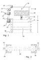
- the motor-driven gate has a safety device 20 with a control circuit 21.
- the control circuit 21 is connected to a motor controller 22, which in turn is connected to a drive motor 24 via an inverter 23.
- the motor controller 22, the inverter 23 and the drive motor 24 are formed according to the prior art, they need not be discussed in detail here.
- the control circuit 21 is associated with a memory 25.
- the motor controller 22 is assigned a memory unit 27.
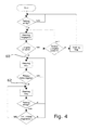
- FIG. 2 For example, a left door guide 26 and a right door guide 28 are shown, both are in FIG. 1 and 3 not shown in detail to better understand the drawing, in particular to show the light rays.
- the gate guides 26, 28 lead a door leaf 30. This has a gate edge 32 with a Torunterkante.
- the door leaf 30 moves within a range of motion 34.
- FIG. 1 the door leaf 30 is drawn in the upper position, in Fig. 3 It is in an intermediate position, it is on the way down and has already covered about 1/2 of its way. The direction of movement is shown by an arrow 36.
- the door leaf 30 touches with its lower door edge a floor 38.
- a spare part 40 file number: STS-01/13 EPA of the range of motion 34 Between the bottom 38 and the current position of the door leaf is located in the representation of Fig. 1 a spare part 40 file number: STS-01/13 EPA of the range of motion 34. This free portion is zero when the bottom door edge is in contact with the bottom 38.
- the two gate guides 26, 28 have e.g. a U-profile. This one has a base and two lateral thighs. In the base, a recess is provided. Behind this is at the left gate guide 26, a bar 42 for arranged in a row light emitter S1, S2 ... Sn arranged. On the opposite side, in the right door guide, behind the recess, a bar 44 for light receiver E1, E2 ... En is arranged.
- the light emitter Sx and the light receiver Ex can work together in different pairs and form a channel in a certain pairing Sx with Ey. All channels together form a light grid.
- the channels are hereinafter referred to on the one hand with transmitter S and receiver E, on the other hand, they are numbered.
- the top channel is channel S1E1
- the bottom channel is channel SnEn.
- the channels with parallel light rays are called Kx in addition to the name SxEx. Out FIG. 1
- the channels K1 to K5 are gleichabstieri, their distance is D, D in the exemplary embodiment has the value 120 mm.
- the channels with parallel light beams advantageously run parallel to the bottom door edge and / or the bottom 38 and / or perpendicular to the direction of movement 36.
- the gate edge 32 In the direction of movement 36, the gate edge 32 has a dimension which has the value H. H is always greater than the distance between two adjacent parallel light emitters, here as d, the difference is at least 10%, in particular at least 20%. As a result, the gate edge 32 always covers at least two parallel channels Kx-1 and Kx, in the embodiment shown it is the channels K1 and K2. The gate edge 32 covers in any case two parallel channels K from.
- an object 46 is shown schematically. It interrupts channel K3. This channel is in the representation of Fig. 1 immediately below the lower edge of the gate.
- the strips 42 and 44 can also be connected elsewhere with the gate guide 26 or 28.
- a strip can be arranged on one side, for example on the flange of the outside of the door, while the other strip is arranged on a flange on the inside of the door.
- the gate edge 32 no longer interrupts the light rays over the entire width of the door leaf 30, but only on a part of this width.
- the requirement is met that each light beam of a particular channel is at least partially located in the movement region 34 or can be interrupted by the gate edge 32.
- the light emitters and light receivers are disposed on different sides of the door leaf 30.
- the receiver E in Fig. 1 it is also possible to arrange mirrors, and the receivers can be arranged next to the transmitters.
- the safety device 20 monitors, inter alia, three individual parallel channels K, which are adjacent and run along with the gate edge 32 step by step. They are called adjacent monitoring channels. You always have the number three. Two of these monitoring channels are usually covered by the door leaf 30, in FIG. 3 it is the channels K2 and K3. The third monitoring channel K4 is located near the lower edge of the door. It is the channel K with a parallel beam of light, which is closer to the bottom edge of the door within the free part 40 than all other parallel channels. This applies both to the gate opening and the gate closing. When opening the gate, the blanking device is normally without function, but it can also be used when opening the gate.
- the three adjacent monitoring channels are each monitored together, this is done serially or in parallel.
- the gate edge releases the channel K3 after a short distance. Once this is the case, a new grouping is formed, the three monitoring channels are then formed by the channels K1 and K2, see in particular FIG. 3 , as well as K3.
- the safety device 20 detects and stores the speed of the door leaf 30 at the location of each individual channel K.
- the gate edge 32 may later pass through the light grid maximally with this location-dependent speed plus a defined tolerance v max .
- a minimum opening and closing speed is required only at the top between the channels K1 and K2, there with the value v minO and between the channels Kn-1 and Kn, there with the value v minU .
- the position of the gate is monitored with a timer. If the door stops automatically in a position where it interrupts the channels K1 or Kn-1, this results in an error signal.
- the time-out when the channel K1 is interrupted advantageously corresponds to a vminO of, for example, 0.05 m / s
- the time-out when the channel Kn-1 is interrupted corresponds to a speed vminU of, for example, 0.01 m / s.
- the polling of the individual light receivers preferably takes place in the multiplex method. Following the monitoring of the three monitoring channels, the other channels located in the free part 40 are queried and monitored. If at least one light beam of these further channels or the lower light beam of the three adjacent monitoring channels is interrupted, the safety device 20 emits an error signal and stops the door leaf or the door, reverses or makes another safety movement.
- the uppermost parallel channel K1 is mainly used for edge detection. An interruption of the light beam of this channel with objects other than the gate edge 32 leads only with a time delay to switch off the light grid output and output an error signal. K1 is therefore not directly intended for monitoring, but can be specified accordingly.
- the motor controller 22 may set a test output before re-closing from this position.
- the safety device 20 notes the current edge edge position, it is stored in the memory 25.
- the safety device 20 counts the respectively traversed by the gate edge 32 parallel channels K. In the embodiment according to FIG. 3 these are the channels K1 to K3. The door movement is only released again when all light rays below this position are free. If this is the case, the new edge edge position is determined by the two upper monitoring channels.
- the safety device 20 interrupts after two seconds operationally. If at the next door opening the lowest two channels K become free again, the output switches on again. If the door is closed, the light transmitters can be switched off for energy saving reasons and the test input can be set. The receiver should remain switched on. However, if the receiver is switched off, the output of the safety device 20 remains interrupted until the channels K are clear again. Only from this point on the gate recognition works again.
- the door leaf 30 is located in above the light grid.
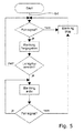
- the closing process starts with a closing command being entered at the Start position. This can be done via a button, a remote control or the like.
- the close command is also referred to as a trip signal for door closing.
- the close command is present in the engine controller 22.
- the gate starts to move, it initially moves in the unmonitored area.
- a test of the safety device 20 is performed. Testing is understood to mean complete testing, which not only checks whether the light grid is interrupted by an object, but also checks the functions of the light grid. Via an output line 31, the safety device 20 reports the test result. Only if the test is successful, the blanking is released.
- Blanking remains enabled only for a specified period of time. Within this time, the gate must reach the top channel K1. If the gate leaf 30 does not reach this uppermost channel K1 within the given time, it comes to a timeout and the blanking is stopped again. However, if the door reaches the channel K1 in the time span, ie below the timeout time, the blanking remains active. Just like the channel K1, the other channels are monitored one after the other. The gate edge 32 next interrupts the channel K2. If this also happens within a specified time window, the blanking remains active. This goes on with all other channels.
- a value table is stored, there is included, when the learning drive (determination from several learning trips) the individual channels Kx are run over one after the other. If the individual channels are reached in the specified time period, no timeout takes place. However, if this is not the case, the blanking stops. Thereafter, a new test takes place. Is it successful, the program jumps back up to the position 60, so the output of the box "light curtain reached?" back. If the test is negative, at least one channel is cleared, the gate moves upwards. If the light curtain has detected this, the program returns to position 60. Blanking is active. But if the at least one channel is not cleared, the program jumps back to position 62, so between "Timeout door movement?" and "Blanking stop". All channels still under the door edge are monitored. If an object is detected in them, the gate movement stops, the blanking is switched off.
- a driving signal is determined by means of the light grid. Only a driving signal in the area of the light grid itself can be obtained via the light grid.
- the drive signal can not be obtained via the light grid, but also on the drive itself, for example by means of a sensor 29 which is assigned to the drive motor 24.
- a sensor 29 which is assigned to the drive motor 24.
- Hall sensors are used to detect the rotation of the motor or its output shaft.
- Other sensors, such as rotary encoders, perforated discs with light scanning etc. are possible.
- a driving signal is also obtained in the region above the light grid.
- FIG. 5 shows an embodiment in which the driving signal is achieved via such a sensor 29, as in FIG. 3 is drawn.
- the light grid is then used only insofar as the uppermost channel, the channel K1, to that extent is monitored whether the door leaf 30 has reached this channel or not.
- the dual function of the other channels K2 to Kn, to be responsible for detecting a foreign object in the region of the light grid as well as for detecting the gate movement, is then not necessary.
- the door movement is no longer checked and detected by the channels K2 to Kn.
- the driving signal can be obtained both via a sensor 29 and via the channels K1 to Kn.
- FIG. 6 is also, as in training after FIG. 5 monitoring the driving signal. In this case, however, it is not the uppermost channel of the light grid, ie the channel K1, which is monitored to see if the door reaches this channel. As long as the drive signal is present, the blanking remains enabled or active. If there is no travel signal, it is monitored whether a predetermined minimum time for timed door movement has already expired. If this is the case, the blanking is stopped. As long as this is not the case and a drive signal is present, the blanking remains active.
- FIG. 7 corresponds to the execution after FIG. 6 , but now the monitoring of "Timeout door movement" is omitted. As long as there is a drive signal after the start command, that is, the sensor 29 provides a signal, the blanking remains active. If there is no drive signal, blanking is stopped.
Landscapes
- Power-Operated Mechanisms For Wings (AREA)
Applications Claiming Priority (1)
| Application Number | Priority Date | Filing Date | Title |
|---|---|---|---|
| DE102013207773 | 2013-04-29 |
Publications (1)
| Publication Number | Publication Date |
|---|---|
| EP2799384A1 true EP2799384A1 (fr) | 2014-11-05 |
Family
ID=49885133
Family Applications (1)
| Application Number | Title | Priority Date | Filing Date |
|---|---|---|---|
| EP14150059.5A Withdrawn EP2799384A1 (fr) | 2013-04-29 | 2014-01-02 | Porte motorisée dotée d'un dispositif de sécurité |
Country Status (2)
| Country | Link |
|---|---|
| EP (1) | EP2799384A1 (fr) |
| DE (2) | DE202014101131U1 (fr) |
Cited By (3)
| Publication number | Priority date | Publication date | Assignee | Title |
|---|---|---|---|---|
| CN105203303A (zh) * | 2015-09-25 | 2015-12-30 | 森赫电梯股份有限公司 | 一种电梯光幕测试台 |
| JP2022546942A (ja) * | 2019-08-27 | 2022-11-10 | マランテック アントリープス ウント シュトイエルングステヒニク ゲーエムベーハー ウント コー.カーゲー | ドアシステム内のドア位置を決定するための方法 |
| EP4603669A1 (fr) * | 2024-02-16 | 2025-08-20 | Novoferm Tormatic GmbH | Procédé de fonctionnement d'une porte, grille de détection et ensemble porte |
Families Citing this family (4)
| Publication number | Priority date | Publication date | Assignee | Title |
|---|---|---|---|---|
| DE102015101017B4 (de) | 2015-01-23 | 2018-02-22 | Efaflex Tor- Und Sicherheitssysteme Gmbh & Co. Kg | Verfahren zur Steuerung einer Toranordnung sowie derartige Toranordnung und eine Sicherheitseinrichtung hierfür |
| DE102018104314A1 (de) * | 2018-02-26 | 2019-08-29 | Marantec Antriebs- Und Steuerungstechnik Gmbh & Co. Kg | Toranlage |
| CN112960523B (zh) * | 2021-02-01 | 2022-11-04 | 宁波职业技术学院 | 一种三维探测电梯光幕装置 |
| CN115246608B (zh) * | 2022-03-22 | 2024-01-30 | 菱王电梯有限公司 | 电梯、控制方法以及存储介质 |
Citations (7)
| Publication number | Priority date | Publication date | Assignee | Title |
|---|---|---|---|---|
| DE29901664U1 (de) * | 1999-02-03 | 1999-04-15 | Samaco GmbH, 77694 Kehl | Hubtor mit Lichtgitter-Überwachungseinrichtung |
| EP0902158B1 (fr) | 1997-09-09 | 2003-02-12 | Efaflex Transport- Und Lagertechnik Gmbh | Dispositif de sécurité pour dispositifs entraínés par moteur |
| EP0902157B1 (fr) | 1997-09-09 | 2003-03-26 | Efaflex Transport- Und Lagertechnik Gmbh | Porte entraínée par un moteur avec dispositif de sécurité |
| DE102005003794A1 (de) * | 2005-01-26 | 2006-08-03 | Cedes Ag | Vorrichtung zur Absicherung eines angetriebenen Bewegungselements |
| WO2009090097A2 (fr) * | 2008-01-16 | 2009-07-23 | Cedes Ag | Système de sécurité pour la sécurisation d'un élément mobile guidé, en déplacement, contre des collisions involontaires |
| EP2374985A2 (fr) | 2010-04-08 | 2011-10-12 | Strack Lift Automation GmbH | Porte motorisée dotée d'un dispositif de sécurité |
| DE102010017398B3 (de) * | 2010-06-16 | 2011-12-01 | Feig Electronic Gmbh | Verfahren zum Betrieb eines Tores sowie Vorrichtung zum Betrieb eines Tores |
-
2014
- 2014-01-02 EP EP14150059.5A patent/EP2799384A1/fr not_active Withdrawn
- 2014-01-02 DE DE202014101131.5U patent/DE202014101131U1/de not_active Expired - Lifetime
- 2014-01-02 DE DE102014200004.1A patent/DE102014200004A1/de not_active Withdrawn
Patent Citations (7)
| Publication number | Priority date | Publication date | Assignee | Title |
|---|---|---|---|---|
| EP0902158B1 (fr) | 1997-09-09 | 2003-02-12 | Efaflex Transport- Und Lagertechnik Gmbh | Dispositif de sécurité pour dispositifs entraínés par moteur |
| EP0902157B1 (fr) | 1997-09-09 | 2003-03-26 | Efaflex Transport- Und Lagertechnik Gmbh | Porte entraínée par un moteur avec dispositif de sécurité |
| DE29901664U1 (de) * | 1999-02-03 | 1999-04-15 | Samaco GmbH, 77694 Kehl | Hubtor mit Lichtgitter-Überwachungseinrichtung |
| DE102005003794A1 (de) * | 2005-01-26 | 2006-08-03 | Cedes Ag | Vorrichtung zur Absicherung eines angetriebenen Bewegungselements |
| WO2009090097A2 (fr) * | 2008-01-16 | 2009-07-23 | Cedes Ag | Système de sécurité pour la sécurisation d'un élément mobile guidé, en déplacement, contre des collisions involontaires |
| EP2374985A2 (fr) | 2010-04-08 | 2011-10-12 | Strack Lift Automation GmbH | Porte motorisée dotée d'un dispositif de sécurité |
| DE102010017398B3 (de) * | 2010-06-16 | 2011-12-01 | Feig Electronic Gmbh | Verfahren zum Betrieb eines Tores sowie Vorrichtung zum Betrieb eines Tores |
Cited By (4)
| Publication number | Priority date | Publication date | Assignee | Title |
|---|---|---|---|---|
| CN105203303A (zh) * | 2015-09-25 | 2015-12-30 | 森赫电梯股份有限公司 | 一种电梯光幕测试台 |
| JP2022546942A (ja) * | 2019-08-27 | 2022-11-10 | マランテック アントリープス ウント シュトイエルングステヒニク ゲーエムベーハー ウント コー.カーゲー | ドアシステム内のドア位置を決定するための方法 |
| US12098582B2 (en) | 2019-08-27 | 2024-09-24 | Marantec Antriebs-Und Steuerungstechnik Gmbh & Co. Kg | Method for determining a position of a door in a door system |
| EP4603669A1 (fr) * | 2024-02-16 | 2025-08-20 | Novoferm Tormatic GmbH | Procédé de fonctionnement d'une porte, grille de détection et ensemble porte |
Also Published As
| Publication number | Publication date |
|---|---|
| DE202014101131U1 (de) | 2014-03-25 |
| DE102014200004A1 (de) | 2014-10-30 |
Similar Documents
| Publication | Publication Date | Title |
|---|---|---|
| EP2374985A2 (fr) | Porte motorisée dotée d'un dispositif de sécurité | |
| DE202014101131U1 (de) | Motorisch angetriebenes Tor mit einer Sicherheitseinrichtung | |
| EP2586959B1 (fr) | Dispositif de sécurisation, dispositif de fermeture et unité d'évaluation | |
| EP2506034B1 (fr) | Dispositif de capteur, dispositif de sécurité, porte et procédé de contrôle du mouvement | |
| EP1353196B1 (fr) | Détection d'un objet et barrière optique | |
| EP3584400B1 (fr) | Porte de protection et procédé de fonctionnement d'une porte de protection | |
| EP2404859B1 (fr) | Dispositif de surveillance pour sécuriser un élément entraîné | |
| DE102010017398B3 (de) | Verfahren zum Betrieb eines Tores sowie Vorrichtung zum Betrieb eines Tores | |
| DE10027156A1 (de) | Schutzeinrichtung für Maschinen, wie Abkantpressen, Schneidmaschinen, Stanzmaschinen oder dergleichen | |
| EP0902158A2 (fr) | Dispositif de sécurité pour dispositifs entraínés par moteur | |
| DE102005000753A1 (de) | Steuerungsvorrichtung einer Verstelleinrichtung eines Kraftfahrzeugs, insbesondere eines Kraftfahrzeugfensterhebers | |
| DE10329881A1 (de) | Lichtgitter | |
| DE102008044990A1 (de) | Verfahren und Vorrichtung zur Ansteuerung und/oder Überwachung eines motorisch angetriebenen Flügels während der Öffnungsphase | |
| DE102004026218A1 (de) | Auf einen Hindernisdetektor ansprechende Einrichtung und Verfahren zum Betätigen einer bewegbaren Barriere | |
| DE102012011117A1 (de) | Verstellsystem für ein Fahrzeug und Verfahren zum Verstellen eines verstellbaren Elements für ein Fahrzeug | |
| EP1841942B1 (fr) | Dispositif pour sécuriser un élément mobile entraîné | |
| DE102010014806B4 (de) | Torantriebsvorrichtung, damit versehener Gebäudeabschluss, Torsystem und Herstell- und Antriebsverfahren | |
| DE29901664U1 (de) | Hubtor mit Lichtgitter-Überwachungseinrichtung | |
| EP0678649A1 (fr) | Volet roulant et dispositif de contrôle | |
| EP3660251A1 (fr) | Dispositif de protection, en particulier portail industriel | |
| DE102014015588A1 (de) | Motorisch betätigbare Überdachung | |
| EP3074583B1 (fr) | Procédé d'entrainement de porte industrielle avec dispositif de détection de force | |
| DE102010049978A1 (de) | Verfahren zur Überwachung von Bewegungen an einem Rolltor sowie Vorrichtung zur Durchführung des Verfahrens | |
| DE102016006706A1 (de) | Tor, insbesondere Sektionaltor und Torantrieb | |
| DE102014007513A1 (de) | Antriebsvorrichtung für eine Spritzgießmaschine |
Legal Events
| Date | Code | Title | Description |
|---|---|---|---|
| PUAI | Public reference made under article 153(3) epc to a published international application that has entered the european phase |
Free format text: ORIGINAL CODE: 0009012 |
|
| 17P | Request for examination filed |
Effective date: 20140102 |
|
| AK | Designated contracting states |
Kind code of ref document: A1 Designated state(s): AL AT BE BG CH CY CZ DE DK EE ES FI FR GB GR HR HU IE IS IT LI LT LU LV MC MK MT NL NO PL PT RO RS SE SI SK SM TR |
|
| AX | Request for extension of the european patent |
Extension state: BA ME |
|
| STAA | Information on the status of an ep patent application or granted ep patent |
Free format text: STATUS: THE APPLICATION IS DEEMED TO BE WITHDRAWN |
|
| 18D | Application deemed to be withdrawn |
Effective date: 20150507 |