EP0699612A2 - Appareil de pliage - Google Patents
Appareil de pliage Download PDFInfo
- Publication number
- EP0699612A2 EP0699612A2 EP95108275A EP95108275A EP0699612A2 EP 0699612 A2 EP0699612 A2 EP 0699612A2 EP 95108275 A EP95108275 A EP 95108275A EP 95108275 A EP95108275 A EP 95108275A EP 0699612 A2 EP0699612 A2 EP 0699612A2
- Authority
- EP
- European Patent Office
- Prior art keywords
- spring
- roller
- lever
- arm
- folding apparatus
- Prior art date
- Legal status (The legal status is an assumption and is not a legal conclusion. Google has not performed a legal analysis and makes no representation as to the accuracy of the status listed.)
- Granted
Links
- 230000007246 mechanism Effects 0.000 claims abstract description 18
- 230000000694 effects Effects 0.000 claims description 3
- 238000013016 damping Methods 0.000 claims description 2
- 230000000149 penetrating effect Effects 0.000 claims 1
- 230000036316 preload Effects 0.000 description 4
- 238000010009 beating Methods 0.000 description 3
- 230000037431 insertion Effects 0.000 description 3
- 238000003780 insertion Methods 0.000 description 3
- 230000002028 premature Effects 0.000 description 3
- 230000007797 corrosion Effects 0.000 description 1
- 238000005260 corrosion Methods 0.000 description 1
- 210000003746 feather Anatomy 0.000 description 1
- 230000010355 oscillation Effects 0.000 description 1
- 230000001603 reducing effect Effects 0.000 description 1
Images


Classifications
-
- B—PERFORMING OPERATIONS; TRANSPORTING
- B65—CONVEYING; PACKING; STORING; HANDLING THIN OR FILAMENTARY MATERIAL
- B65H—HANDLING THIN OR FILAMENTARY MATERIAL, e.g. SHEETS, WEBS, CABLES
- B65H29/00—Delivering or advancing articles from machines; Advancing articles to or into piles
- B65H29/58—Article switches or diverters
-
- B—PERFORMING OPERATIONS; TRANSPORTING
- B65—CONVEYING; PACKING; STORING; HANDLING THIN OR FILAMENTARY MATERIAL
- B65H—HANDLING THIN OR FILAMENTARY MATERIAL, e.g. SHEETS, WEBS, CABLES
- B65H29/00—Delivering or advancing articles from machines; Advancing articles to or into piles
- B65H29/12—Delivering or advancing articles from machines; Advancing articles to or into piles by means of the nip between two, or between two sets of, moving tapes or bands or rollers
-
- B—PERFORMING OPERATIONS; TRANSPORTING
- B65—CONVEYING; PACKING; STORING; HANDLING THIN OR FILAMENTARY MATERIAL
- B65H—HANDLING THIN OR FILAMENTARY MATERIAL, e.g. SHEETS, WEBS, CABLES
- B65H2404/00—Parts for transporting or guiding the handled material
- B65H2404/20—Belts
- B65H2404/26—Particular arrangement of belt, or belts
- B65H2404/261—Arrangement of belts, or belt(s) / roller(s) facing each other for forming a transport nip
-
- B—PERFORMING OPERATIONS; TRANSPORTING
- B65—CONVEYING; PACKING; STORING; HANDLING THIN OR FILAMENTARY MATERIAL
- B65H—HANDLING THIN OR FILAMENTARY MATERIAL, e.g. SHEETS, WEBS, CABLES
- B65H2404/00—Parts for transporting or guiding the handled material
- B65H2404/20—Belts
- B65H2404/26—Particular arrangement of belt, or belts
- B65H2404/261—Arrangement of belts, or belt(s) / roller(s) facing each other for forming a transport nip
- B65H2404/2613—Means for changing the transport path, e.g. deforming, lengthening
-
- B—PERFORMING OPERATIONS; TRANSPORTING
- B65—CONVEYING; PACKING; STORING; HANDLING THIN OR FILAMENTARY MATERIAL
- B65H—HANDLING THIN OR FILAMENTARY MATERIAL, e.g. SHEETS, WEBS, CABLES
- B65H2701/00—Handled material; Storage means
- B65H2701/10—Handled articles or webs
- B65H2701/19—Specific article or web
- B65H2701/1932—Signatures, folded printed matter, newspapers or parts thereof and books
Definitions
- the invention relates generally to a printing press and, more particularly, to an insertion belt mechanism of a folder for a printing press for displaying signatures.
- Entry belt systems are commonly used to convey signatures from a press to a stack.
- An infeed belt system typically includes several infeed belt mechanisms spaced side by side so that they come in contact with the signatures across their width.
- Each infeed belt mechanism includes an infeed belt on one side and a corresponding counter-rotating infeed belt on the other side to form a signature pass so that the signature can be gripped on both sides and conveyed through the signature pass.
- the signatures often leave the signature run in order to be accommodated in the pockets of one or more paddlewheels.
- the signatures are then placed on a stack, as in the U.S. Patent No. 5,112,033, which is hereby incorporated as a reference patent.
- the infeed belts normally have guide rollers and a drive roller which are arranged on the inside of the infeed belt for guiding and driving it.
- One exit roller is usually fixed while the other exit roller is fixed in the direction of the attached roller is biased by a single spring to maintain the hard grip on the signature when entering a paddle wheel.
- This hard grip or pressure is necessary to support the transport of the signatures into the paddle wheels and their inclusion in them.
- the exit rollers which are spring-loaded, hit this gap between the signatures, they press against the firmly attached rollers and release again when they hit the front edge of the next signature. This creates an oscillation phenomenon, which places a high dynamic load on the fixed rollers.
- Another object of the invention is to prevent premature wear of bearings, belts, or other components.
- the present invention thus provides a folder which has the following features: at least one infeed belt mechanism with a first infeed belt and a first exit roller and one corresponding second infeed belt and a second outlet roller, the first and second infeed belts forming a signature run for displaying the signatures; the first exit roller is rotatable about a first roller axis, but is otherwise fixed; a lever supporting the second exit roller, the second exit roller being rotatably supported on the lever about a second roller axis; an arm connected to the lever having a first side and an opposite second side; a first spring acting against the first side of the arm to urge the lever and the second exit roller toward the first exit roller; and a second spring acting against the second side of the arm.
- This double spring arrangement reduces the beating that occurs when the signatures pass through the infeed belt mechanism and at the same time prevents premature wear of the bearings, belts and other components.
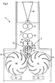
- Fig. 1 shows a conventional folder 1 for a web-fed rotary printing press.
- the printed web is over a funnel 30 passed and folded. After folding, the web is passed through the nip between respective upper and lower pull rollers 31 and 32 and guide rollers 33 and arrives at a cutting cylinder 34 on which the web is cut off and signatures are formed.
- a web separator 35 is located between the upper and lower pull rollers 31 and 32.
- the signatures are then conveyed through an introduction belt system 2 into the respective pockets 50 and 51 of respective paddle wheels 40 and 41. During the rotation of the paddle wheels 40 and 41, the signatures are placed on respective stacks 55 and 56.
- the infeed belt system 2 comprises at least one infeed belt mechanism and preferably more than one side-by-side and parallel infeed belt mechanism with coaxial exit rollers, including a first infeed belt mechanism 10 for gripping the signatures across their width.
- the first infeed belt mechanism 10 includes a left infeed belt 11 and a corresponding right infeed belt 21 which form a signature pass for the respective signatures, as shown by the signatures 3 and 4 in FIG. 2. When the signatures pass through, there is a gap 5 between the rear edge of the signature 3 and the front edge of the signature 4.
- the infeed belt mechanism 10 also comprises top left rollers 13 and top right rollers 23, which guide rollers or drive rollers for guiding and driving the respective left and right insertion belt 11 and 21 can be.
- the infeed belt mechanism 10 further includes a left exit roller 15 and a corresponding right exit roller 25.
- FIG. 2 shows the infeed band mechanism 10, ie an infeed band mechanism, preferably arranged side by side, which has a left infeed band 11 and includes a corresponding right entry belt 21.
- the left exit roller 15 is supported at one end of a left lever 16, and the left end 16 is fastened at its other end to a bush 18 which is rotatable about a stud 17.
- the stud 17 is attached to a frame part 28 such that the left lever 16 and the left exit roller 15 can be acted upon by a spring preload against the right exit roller 25, as will be described in more detail below.
- the right exit roller 25 is supported at one end of a right lever 26, and the other end of the right lever 26 is supported on a fixed stud 27, which is fixed to the frame part 28, so that the right exit roller 25 can rotate, but is translationally fixed during operation.
- An arm 29 with an upper and lower side is also fastened to the bush 18 by means of a clamping bolt.
- a coil spring 60 is wound around a bias bolt 62 having a bolt head 63 and is movable between the bolt head 63 and the top of the arm 29.
- the preload bolt 62 is screwed into a mounting piece 65 fastened to the frame part 28 and also penetrates through a hole in the arm 29.
- the preload of the coil spring 60 can be changed by tightening or loosening the bolt 62.
- the clamping bolt of the arm 29 can be loosened so that the arm 29 can rotate on the bushing 18 and can be screwed back on later. This can be done without affecting the position of the lever 16, which has its own clamping bolt.
- a second spring 61 which can be made of a rubber-like material, for example, and preferably a high one Has spring constant.
- the second spring 61 also preferably has additional damping properties in order to reduce the effects of forces and vibrations.
- a preferred spring constant for the coil spring would be approximately 22.5-45 kg per 2.54 cm (50-100 lbs / inch) and a preferred spring constant for the second spring is about 225-450 kg per 2.54 cm (500-1000 lbs / inch), however the optimal spring constant may vary depending on web thickness, normal operating speeds and other factors.
- the individual signatures 3, 4 are moved between the corresponding infeed belts 11, 21.
- the spiral spring 60 forces the arm 29 and thus the lever 16 and the left discharge roller 15 to move through the bushing 18 in the direction of the right discharge roller 25.
- the second spring 61 counteracts this movement.
- the forces acting on the bolt head 63 are significantly reduced by the existing spring, which has a high spring constant.
- the illustrated curve 70 shows the variation of the forces acting on the bolt head 63 during operation of the machine, while the illustrated curve 71 shows the effects of forces on a similar bolt head, where only a coil spring acts between one arm and the bolt head.
- the time period between the vertices of curve 71 is the time period in which an individual signature passes the exit rollers.
Landscapes
- Engineering & Computer Science (AREA)
- Mechanical Engineering (AREA)
- Folding Of Thin Sheet-Like Materials, Special Discharging Devices, And Others (AREA)
- Feeding Of Articles By Means Other Than Belts Or Rollers (AREA)
Applications Claiming Priority (2)
| Application Number | Priority Date | Filing Date | Title |
|---|---|---|---|
| US297728 | 1981-08-31 | ||
| US08/297,728 US5490666A (en) | 1994-08-29 | 1994-08-29 | Folder with spring-biased exit roller |
Publications (3)
| Publication Number | Publication Date |
|---|---|
| EP0699612A2 true EP0699612A2 (fr) | 1996-03-06 |
| EP0699612A3 EP0699612A3 (fr) | 1997-01-29 |
| EP0699612B1 EP0699612B1 (fr) | 1999-11-24 |
Family
ID=23147506
Family Applications (1)
| Application Number | Title | Priority Date | Filing Date |
|---|---|---|---|
| EP95108275A Expired - Lifetime EP0699612B1 (fr) | 1994-08-29 | 1995-05-31 | Appareil de pliage |
Country Status (5)
| Country | Link |
|---|---|
| US (1) | US5490666A (fr) |
| EP (1) | EP0699612B1 (fr) |
| JP (1) | JPH0872433A (fr) |
| CA (1) | CA2152708C (fr) |
| DE (2) | DE19519373A1 (fr) |
Cited By (1)
| Publication number | Priority date | Publication date | Assignee | Title |
|---|---|---|---|---|
| WO2000000408A1 (fr) * | 1998-06-17 | 2000-01-06 | Sca Packaging Marketing Nv | Materiau d'emballage facilement imprimable et recyclable, proce de de production dudit materiau |
Families Citing this family (8)
| Publication number | Priority date | Publication date | Assignee | Title |
|---|---|---|---|---|
| DE4420186C2 (de) * | 1994-06-09 | 1997-04-17 | Heidelberger Druckmasch Ag | Vorrichtung zum extemporären Abheben einer Transportrolle im Anleger einer Maschine zur Bogenbearbeitung |
| US5735784A (en) * | 1995-06-07 | 1998-04-07 | Ranpak Corp. | Loading assembly for a cushioning conversion machine |
| JPH11506988A (ja) * | 1995-06-07 | 1999-06-22 | ランパック コーポレイション | クッション変換機のローディングアッセンブリーおよび方法 |
| US5937757A (en) * | 1998-01-07 | 1999-08-17 | Goss Graphic Systems, Inc. | Gap adjusting device with pressure relief for a second fold roller |
| DE10157252A1 (de) * | 2001-11-22 | 2003-06-05 | Heidelberger Druckmasch Ag | Falzwerk mit einer Falzwalzenbelastung |
| EP2511210A1 (fr) * | 2009-12-11 | 2012-10-17 | Fuji Electric Co., Ltd. | Appareil destiné au transfert de substrat souple |
| JP2014084213A (ja) * | 2012-10-25 | 2014-05-12 | Toshiba Corp | 紙葉類分岐搬送装置 |
| US20240208733A1 (en) * | 2022-12-21 | 2024-06-27 | Shaw Industries Group, Inc. | Auxiliary roller system for use with belt-feed systems |
Citations (1)
| Publication number | Priority date | Publication date | Assignee | Title |
|---|---|---|---|---|
| US5112033A (en) | 1990-05-09 | 1992-05-12 | Harris Graphics Corporation | Folder apparatus for a web-fed printing press |
Family Cites Families (16)
| Publication number | Priority date | Publication date | Assignee | Title |
|---|---|---|---|---|
| US1849958A (en) * | 1932-03-15 | Tabloid sheet slitter | ||
| US655355A (en) * | 1895-02-28 | 1900-08-07 | Walter Scott | Printing-machine. |
| DE371784C (de) * | 1920-12-09 | 1923-03-22 | Fritz Hoffmann | Vorgelege mit Spannvorrichtung fuer Riementriebe u. dgl. |
| US1883224A (en) * | 1926-05-26 | 1932-10-18 | Wood Newspaper Mach Corp | Folding and delivery mechanism |
| SU440877A1 (ru) * | 1973-09-05 | 1980-04-30 | Типография Издательства "Известия" | Способ образовани стопок газет |
| DE2541502C3 (de) * | 1975-09-17 | 1983-12-08 | Albert-Frankenthal Ag, 6710 Frankenthal | Einrichtung zum Verlangsamen der aus dem Falzapparat einer Rotationsdruckmaschine in das Ablegeschaufelrad abzulegenden Druckexemplare |
| GB2070733B (en) * | 1980-02-28 | 1983-06-02 | Godolloi Agrartudomanyi Egyete | Flexible couplings |
| JPS57138847U (fr) * | 1981-02-24 | 1982-08-30 | ||
| US4496339A (en) * | 1983-04-18 | 1985-01-29 | Moll Richard J | Apparatus for setting roller clearance |
| US4537390A (en) * | 1984-06-14 | 1985-08-27 | Rockwell International Corporation | High speed folder fly |
| GB2168686A (en) * | 1984-12-19 | 1986-06-25 | De La Rue Syst | Sheet stacking wheel |
| JP2511075B2 (ja) * | 1987-11-11 | 1996-06-26 | 三菱重工業株式会社 | 輪転印刷機の折機 |
| DE3838314A1 (de) * | 1988-11-11 | 1990-05-17 | Koenig & Bauer Ag | Falzklappenzylinder fuer eine rollenrotationsdruckmaschine |
| US5064180A (en) * | 1990-04-09 | 1991-11-12 | Harris Graphics Corporation | Electrostatic diverter |
| US5203846A (en) * | 1991-11-12 | 1993-04-20 | A. B. Dick Company | Media feed roll apparatus and method for its use |
| DE4241810C2 (de) * | 1992-12-11 | 2001-01-04 | Heidelberger Druckmasch Ag | Formatvariabler Kombinationsfalzapparat |
-
1994
- 1994-08-29 US US08/297,728 patent/US5490666A/en not_active Expired - Fee Related
-
1995
- 1995-05-26 DE DE19519373A patent/DE19519373A1/de not_active Withdrawn
- 1995-05-31 DE DE59507277T patent/DE59507277D1/de not_active Expired - Fee Related
- 1995-05-31 EP EP95108275A patent/EP0699612B1/fr not_active Expired - Lifetime
- 1995-06-27 CA CA002152708A patent/CA2152708C/fr not_active Expired - Fee Related
- 1995-08-25 JP JP7217606A patent/JPH0872433A/ja not_active Ceased
Patent Citations (1)
| Publication number | Priority date | Publication date | Assignee | Title |
|---|---|---|---|---|
| US5112033A (en) | 1990-05-09 | 1992-05-12 | Harris Graphics Corporation | Folder apparatus for a web-fed printing press |
Cited By (1)
| Publication number | Priority date | Publication date | Assignee | Title |
|---|---|---|---|---|
| WO2000000408A1 (fr) * | 1998-06-17 | 2000-01-06 | Sca Packaging Marketing Nv | Materiau d'emballage facilement imprimable et recyclable, proce de de production dudit materiau |
Also Published As
| Publication number | Publication date |
|---|---|
| EP0699612B1 (fr) | 1999-11-24 |
| US5490666A (en) | 1996-02-13 |
| EP0699612A3 (fr) | 1997-01-29 |
| CA2152708C (fr) | 1998-10-06 |
| CA2152708A1 (fr) | 1996-03-01 |
| DE19519373A1 (de) | 1996-03-07 |
| JPH0872433A (ja) | 1996-03-19 |
| DE59507277D1 (de) | 1999-12-30 |
Similar Documents
| Publication | Publication Date | Title |
|---|---|---|
| EP0711724B1 (fr) | Dispositif pour séparer des sections tubulaires perforées | |
| DE3637110C1 (de) | Vorrichtung zum Schneiden und Aufteilen eines kontinuierlichen Stroms von Druckprodukten | |
| EP4477424A2 (fr) | Support de rouleau pour rouleau d'étiquettes et imprimante d'étiquettes | |
| DE3914197C2 (de) | Vorrichtung zum Öffnen einer lose anliegenden Klappe von Briefumschlägen | |
| DE10005323A1 (de) | Vorrichtung zur Produkthandhabung | |
| EP1362819B1 (fr) | Plieuse dans une machine rotative d'impression | |
| EP0699612A2 (fr) | Appareil de pliage | |
| EP0297283A1 (fr) | Dispositif pour scinder un courant d'imprimés | |
| EP0656307A1 (fr) | Cylindre de transport de cahiers | |
| DE69400581T2 (de) | Maschine zum Stapeln mit Schnellmontageeinrichtung | |
| DE19600379C2 (de) | Vorrichtung zum Transport von Exemplaren | |
| EP1858789B1 (fr) | Dispositif pour separer des envois plats se chevauchant | |
| DE19940535A1 (de) | Vorrichtung zum Umlenken von Signaturen | |
| EP0842884A2 (fr) | Dispositif pour absorber de l'énergie pendant la sortie de cahiers | |
| EP1097892B1 (fr) | Dispositif et procédé pour couper et dévier des produits imprimés | |
| DE69226976T2 (de) | Apparat zur Verarbeitung von Briefen | |
| DE19515440A1 (de) | Falzapparat | |
| CH695767A5 (de) | Bedruckstoff verarbeitende Maschine mit einer Transportbandeinrichtung. | |
| DE19519372C2 (de) | Einführbandmechanismus in Modulbauweise | |
| DE102019213305A1 (de) | Bedruckstoff-Transportvorrichtung und Druckmaschine | |
| DE1254158B (de) | Vorrichtung zum Vereinzeln und Abtransportieren des jeweils vordersten Blattes eines Blattstapels | |
| EP1184314A2 (fr) | Dispositif pour le guidage des feuilles, en particulier dans la zone de sortie d'un cylindre de découpage dans un appareil de pliage d'une machine d'impression rotative | |
| EP0896943B1 (fr) | Méthode et dispositif pour la régulation continue d'un matériau imprimable dans un système d'impression | |
| CH629159A5 (en) | Transport device for sheet-shaped recording media | |
| EP1582491B1 (fr) | Dispositif pour transporter des objets plats |
Legal Events
| Date | Code | Title | Description |
|---|---|---|---|
| PUAI | Public reference made under article 153(3) epc to a published international application that has entered the european phase |
Free format text: ORIGINAL CODE: 0009012 |
|
| 17P | Request for examination filed |
Effective date: 19950531 |
|
| AK | Designated contracting states |
Kind code of ref document: A2 Designated state(s): CH DE FR GB IT LI |
|
| PUAL | Search report despatched |
Free format text: ORIGINAL CODE: 0009013 |
|
| AK | Designated contracting states |
Kind code of ref document: A3 Designated state(s): CH DE FR GB IT LI |
|
| 17Q | First examination report despatched |
Effective date: 19980609 |
|
| GRAG | Despatch of communication of intention to grant |
Free format text: ORIGINAL CODE: EPIDOS AGRA |
|
| GRAG | Despatch of communication of intention to grant |
Free format text: ORIGINAL CODE: EPIDOS AGRA |
|
| GRAH | Despatch of communication of intention to grant a patent |
Free format text: ORIGINAL CODE: EPIDOS IGRA |
|
| GRAH | Despatch of communication of intention to grant a patent |
Free format text: ORIGINAL CODE: EPIDOS IGRA |
|
| GRAA | (expected) grant |
Free format text: ORIGINAL CODE: 0009210 |
|
| AK | Designated contracting states |
Kind code of ref document: B1 Designated state(s): CH DE FR GB IT LI |
|
| REG | Reference to a national code |
Ref country code: CH Ref legal event code: EP |
|
| REF | Corresponds to: |
Ref document number: 59507277 Country of ref document: DE Date of ref document: 19991230 |
|
| ITF | It: translation for a ep patent filed | ||
| GBT | Gb: translation of ep patent filed (gb section 77(6)(a)/1977) |
Effective date: 20000203 |
|
| ET | Fr: translation filed | ||
| PLBE | No opposition filed within time limit |
Free format text: ORIGINAL CODE: 0009261 |
|
| STAA | Information on the status of an ep patent application or granted ep patent |
Free format text: STATUS: NO OPPOSITION FILED WITHIN TIME LIMIT |
|
| 26N | No opposition filed | ||
| REG | Reference to a national code |
Ref country code: GB Ref legal event code: IF02 |
|
| PGFP | Annual fee paid to national office [announced via postgrant information from national office to epo] |
Ref country code: GB Payment date: 20030422 Year of fee payment: 9 |
|
| PGFP | Annual fee paid to national office [announced via postgrant information from national office to epo] |
Ref country code: FR Payment date: 20030522 Year of fee payment: 9 |
|
| PGFP | Annual fee paid to national office [announced via postgrant information from national office to epo] |
Ref country code: CH Payment date: 20030530 Year of fee payment: 9 |
|
| PGFP | Annual fee paid to national office [announced via postgrant information from national office to epo] |
Ref country code: DE Payment date: 20030610 Year of fee payment: 9 |
|
| PG25 | Lapsed in a contracting state [announced via postgrant information from national office to epo] |
Ref country code: LI Free format text: LAPSE BECAUSE OF NON-PAYMENT OF DUE FEES Effective date: 20040531 Ref country code: GB Free format text: LAPSE BECAUSE OF NON-PAYMENT OF DUE FEES Effective date: 20040531 Ref country code: CH Free format text: LAPSE BECAUSE OF NON-PAYMENT OF DUE FEES Effective date: 20040531 |
|
| PG25 | Lapsed in a contracting state [announced via postgrant information from national office to epo] |
Ref country code: DE Free format text: LAPSE BECAUSE OF NON-PAYMENT OF DUE FEES Effective date: 20041201 |
|
| REG | Reference to a national code |
Ref country code: CH Ref legal event code: PL |
|
| GBPC | Gb: european patent ceased through non-payment of renewal fee | ||
| PG25 | Lapsed in a contracting state [announced via postgrant information from national office to epo] |
Ref country code: FR Free format text: LAPSE BECAUSE OF NON-PAYMENT OF DUE FEES Effective date: 20050131 |
|
| REG | Reference to a national code |
Ref country code: FR Ref legal event code: ST |
|
| PG25 | Lapsed in a contracting state [announced via postgrant information from national office to epo] |
Ref country code: IT Free format text: LAPSE BECAUSE OF NON-PAYMENT OF DUE FEES;WARNING: LAPSES OF ITALIAN PATENTS WITH EFFECTIVE DATE BEFORE 2007 MAY HAVE OCCURRED AT ANY TIME BEFORE 2007. THE CORRECT EFFECTIVE DATE MAY BE DIFFERENT FROM THE ONE RECORDED. Effective date: 20050531 |