EP0699850A2 - Transmission hydromécanique - Google Patents
Transmission hydromécanique Download PDFInfo
- Publication number
- EP0699850A2 EP0699850A2 EP95306039A EP95306039A EP0699850A2 EP 0699850 A2 EP0699850 A2 EP 0699850A2 EP 95306039 A EP95306039 A EP 95306039A EP 95306039 A EP95306039 A EP 95306039A EP 0699850 A2 EP0699850 A2 EP 0699850A2
- Authority
- EP
- European Patent Office
- Prior art keywords
- hydraulic
- power
- mechanical transmission
- shaft
- motor
- Prior art date
- Legal status (The legal status is an assumption and is not a legal conclusion. Google has not performed a legal analysis and makes no representation as to the accuracy of the status listed.)
- Granted
Links
Images

Classifications
-
- F—MECHANICAL ENGINEERING; LIGHTING; HEATING; WEAPONS; BLASTING
- F16—ENGINEERING ELEMENTS AND UNITS; GENERAL MEASURES FOR PRODUCING AND MAINTAINING EFFECTIVE FUNCTIONING OF MACHINES OR INSTALLATIONS; THERMAL INSULATION IN GENERAL
- F16H—GEARING
- F16H47/00—Combinations of mechanical gearing with fluid clutches or fluid gearing
- F16H47/02—Combinations of mechanical gearing with fluid clutches or fluid gearing the fluid gearing being of the volumetric type
- F16H47/04—Combinations of mechanical gearing with fluid clutches or fluid gearing the fluid gearing being of the volumetric type the mechanical gearing being of the type with members having orbital motion
-
- F—MECHANICAL ENGINEERING; LIGHTING; HEATING; WEAPONS; BLASTING
- F16—ENGINEERING ELEMENTS AND UNITS; GENERAL MEASURES FOR PRODUCING AND MAINTAINING EFFECTIVE FUNCTIONING OF MACHINES OR INSTALLATIONS; THERMAL INSULATION IN GENERAL
- F16H—GEARING
- F16H37/00—Combinations of mechanical gearings, not provided for in groups F16H1/00 - F16H35/00
- F16H37/02—Combinations of mechanical gearings, not provided for in groups F16H1/00 - F16H35/00 comprising essentially only toothed or friction gearings
- F16H37/06—Combinations of mechanical gearings, not provided for in groups F16H1/00 - F16H35/00 comprising essentially only toothed or friction gearings with a plurality of driving or driven shafts; with arrangements for dividing torque between two or more intermediate shafts
- F16H37/08—Combinations of mechanical gearings, not provided for in groups F16H1/00 - F16H35/00 comprising essentially only toothed or friction gearings with a plurality of driving or driven shafts; with arrangements for dividing torque between two or more intermediate shafts with differential gearing
- F16H37/0833—Combinations of mechanical gearings, not provided for in groups F16H1/00 - F16H35/00 comprising essentially only toothed or friction gearings with a plurality of driving or driven shafts; with arrangements for dividing torque between two or more intermediate shafts with differential gearing with arrangements for dividing torque between two or more intermediate shafts, i.e. with two or more internal power paths
- F16H37/084—Combinations of mechanical gearings, not provided for in groups F16H1/00 - F16H35/00 comprising essentially only toothed or friction gearings with a plurality of driving or driven shafts; with arrangements for dividing torque between two or more intermediate shafts with differential gearing with arrangements for dividing torque between two or more intermediate shafts, i.e. with two or more internal power paths at least one power path being a continuously variable transmission, i.e. CVT
- F16H2037/0866—Power-split transmissions with distributing differentials, with the output of the CVT connected or connectable to the output shaft
Definitions
- the present invention relates to a hydraulic/mechanical transmission device for transmitting power from a prime mover to an output, such as from a vehicle engine to the vehicle wheels, by both a hydraulic transmission and a mechanical transmission with variable speed change ratios.
- a well-known hydrostatic continuously variable transmission device that includes a hydraulic pump and a hydraulic motor, which are in communication with each other through a hydraulic closed circuit and at least one of which is constructed into a variable displacement type, is used in various industrial machines and vehicles.
- a hydrostatic continuously variable transmission is excellent in providing continuously variable speed ratio changes in the power transmitted, it is not necessarily of good efficiency in transmitting power whereby it is unsuitable for a vehicle in which the specific fuel consumption is an important consideration.
- a hydraulic/mechanical power transmitting device has been conventionally proposed (see Japanese Patent Application Laid open No. 147148/87), which is designed to transmit power from the prime mover by the cooperation of a hydrostatic continuously variable transmission having an excellent continuously variable speed ratio transmittability and a mechanical power transmitting device having an excellent power transmitting efficiency.
- a hydrostatic continuously variable transmission having an excellent continuously variable speed ratio transmittability
- a mechanical power transmitting device having an excellent power transmitting efficiency.
- the input shaft supplied with the power from the prime mover, the pump shaft of the hydraulic pump, the motor shaft of the hydraulic motor and the power collecting shaft for collecting the power supplied in a divided manner by the hydraulic system and the mechanical system are all independently disposed in parallel to one another, and hence, there is a disadvantage that the number of parallel shafts is increased, resulting in a complicated and large-sized structure.
- a hydraulic/mechanical transmission device comprising; a power dividing device including an input shaft and a pair of first and second output shafts for dividing power supplied from a prime mover to the input shaft so as to transmit the same to both the output shafts; a hydrostatic continuously variable transmission including a hydraulic pump driven by power delivered from the first output shaft, a hydraulic motor which is in communication with the hydraulic pump through a hydraulic closed circuit, and a control plate in which the hydraulic closed circuit is formed, at least one of the hydraulic pump and the hydraulic motor being of a variable displacement type; a mechanical transmission device connected to the second output shaft; and a power collecting shaft for collecting power delivered from both the mechanical transmission device and the hydraulic motor to supply them to a load, wherein the input shaft and the first and second output shafts of the power dividing device are coaxially disposed, the first output shaft being coaxially connected to a pump cylinder of the hydraulic pump, and the power collecting shaft being disposed parallel to the first and second output shafts and co
- the power dividing device, the mechanical transmission device and the power collecting shaft are accommodated in a common casing to constitute a mechanical transmission unit, and the control plate is disposed between the mechanical transmission unit and the hydraulic pump as well as the hydraulic motor in order to rotatably support the first output shaft and the power collecting shaft.
- a differential is connected to the power collecting shaft and accommodated in the casing of the mechanical transmission unit, the differential being disposed parallel to the power collecting shaft, such that either the left or right wheel driving shaft extending from the differential passes along an outer periphery of the continuously variable transmission.
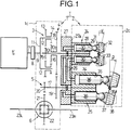
- Fig. 1 is a diagrammatic illustration of a hydraulic/ mechanical transmission device and system for a vehicle according to a preferred embodiment of the present invention.
- Fig. 2 is a diagram which shows the relationship between the angle of the swash plate and the combined speed ratio in a hydrostatic continuously variable transmission in the hydraulic/mechanical transmission of Fig. 1.
- a hydraulic/mechanical transmission device T of this invention is illustrated for a front engine and front drive type or rear engine and rear drive type vehicle.
- the hydraulic/ mechanical transmission device T includes a mechanical transmission unit 1 and a hydrostatic continuously variable transmission 2.
- An engine E as a prime mover is disposed on one side of the mechanical transmission unit 1, and the hydrostatic continuously variable transmission 2 is disposed on the other side of the mechanical transmission unit 1.
- the mechanical transmission unit 1 includes a power dividing device 3, a mechanical transmission device 4, a power collecting shaft 17, a speed-reducing device 5 and a differential 6, which are all contained within a common first casing 1c.
- the power dividing device 3 is constructed into a planetary gear type, and includes an input shaft 9 connected to a crankshaft 7 of the engine E via a torque damper 8, a first output shaft 101 which is coaxially in line with the input shaft 9, and a second output shaft 102 which concentrically surrounds the first output shaft 101.
- a carrier 11 is fixedly mounted to the input shaft 9 and has a plurality of pinion shafts 12 on its outer periphery, which are parallel to the input shaft 9.
- a pair of larger and smaller diameter pinion gears 13 and 14 coupled to each other are rotatably carried on each of the pinion shafts 12.
- a smaller diameter sun gear 15 is fixedly mounted on the first output shaft 101 and meshed with the larger diameter pinion gear 13.
- a larger diameter sun gear 16 is fixedly mounted in the output shaft 102 and meshed with the smaller diameter pinion gear 14.
- the mechanical transmission unit 1 includes a gear 18 which is fixedly mounted on the second output shaft 102 and a gear 19 which is fixedly mounted on the power collecting shaft 17 and meshed with the gear 18.
- the power collecting shaft 17 is disposed in parallel with the first and second output shafts 101 and 102.
- the speed reducing device 5 includes a smaller diameter gear 20 fixedly mounted on the power collecting shaft 17, and a larger diameter gear 21 which is fixedly mounted on the differential case 22 of the differential 6 and is meshed with the smaller diameter gear 20.
- the differential 6 is conventionally well-known and designed to distribute power transmitted to the differential case 22 from the larger diameter gear 21 to left and right wheel driving shafts 23 L and 23 R .
- the differential 6 is disposed in parallel to the power collecting shaft 17, so that one of the wheel driving shafts 23 L and 23 R extends along an outer periphery of the continuously variable transmission 2, e.g., shaft 23 R extends below the continuously variable transmission 2 in the illustrated embodiment.
- the continuously variable transmission 2 includes a hydraulic pump 24, a hydraulic motor 25, and a control plate 27 in which a hydraulic closed circuit 26 which connects the hydraulic pump 24 and the hydraulic motor 25 to each other is formed.
- the control plate 27 is secured to one side of a first casing 1c adjacent the mechanical transmitting unit 1 and rotatably supports the first output shaft 101 and the power collecting shaft 17. Accordingly, the control plate 27 is disposed between the mechanical transmitting unit 1 and the hydraulic pump 24 and the hydraulic motor 25.
- the hydraulic pump 24 is constructed in a variable displacement type, and includes a pump cylinder block 28 coaxially connected to the first output shaft 101 and rotatably and slidably disposed on a hydraulic pressure dispensing surface 27a of the control plate 27, a large number of pump plungers 30 are slidably fitted respectively in a large number of cylinder bores 29 provided in an annular arrangement in the pump cylinder block 28 to surround the axis of thereof, and a pump swash plate 32 which is tiltable at a variable angle and against which a shoe 31 oscillatably mounted at a tip end of each of the pump plungers 30 slidably abuts.
- the pump swash plate 32 is capable of being turned about a trunnion shaft 33 disposed perpendicular to the axis of the pump cylinder block 28 between a righted position in which the pump swash plate 32 intersects the axis of the pump cylinder block 28 at right angles, and a tilted-down position in which the pump swash plate is tilted down at a predetermined maximum inclination with respect to the axis of the pump cylinder block 28. If the inclination angle ⁇ from the righted position of the pump swash plate 32 is increased, the reciprocating stroke of each of the pump plungers 30 can be increased.
- the hydraulic motor 25 is also constructed in a variable displacement type, and includes a motor cylinder block 34 coaxially connected to the power collecting shaft 17 and rotatably and slidably disposed on a hydraulic pressure dispensing surface 27a of the control plate 27, a large number of motor plungers 36 are slidably fitted respectively in a large number of cylinder bores 35 provided in the motor cylinder block 34 to surround an axis of the motor cylinder block 34, and a motor swash plate 38 against which a shoe 37 oscillatably mounted at a tip end of each of the motor plungers 36 slidably abuts.
- the motor swash plate 38 is capable of being turned about a trunnion shaft 39 disposed perpendicular to the axis of the motor cylinder 34 between a righted position in which the motor swash plate 38 intersects the axis of the motor cylinder 34 at right angles, and a tilted-down position in which the motor swash plate 38 is tilted down at a predetermined maximum inclination with respect to the axis of the motor cylinder block 34. If the inclination angle ⁇ from the righted position of the motor swash plate 38 is increased, the reciprocating stroke of each of the motor plungers 36 can be increased.
- the second casing 2c in which the hydraulic pump 24 and the hydraulic motor 25 are contained, is secured to the control plate 27.
- the pump plunger is moved in one reciprocation for one rotation of the pump cylinder block 28 in the cylinder bore 29 with a stroke corresponding to the inclination angle ⁇ of the pump swash plate 32, thereby performing discharging and sucking motions. Therefore, the hydraulic pressure discharged from each cylinder bore 29 is transferred via a higher pressure side of the hydraulic closed circuit 26 to the corresponding cylinder bore 35 of the motor cylinder block 34 to provide an expanding motion to the corresponding motor plunger 36.
- each of the hydraulic pump 24 and the hydraulic motor 25 is determined by the stroke of the corresponding plunger 30, 36, i.e., the angle ⁇ , ⁇ of the swash plate 32, 38, and the gear ratio of the continuously variable transmission 2 can be controlled continuously by varying the angles ⁇ , ⁇ of the swash plates 32, 38.
- the power transmitted to the smaller diameter pinion gear 14 is transmitted through the larger diameter sun gear 16 to the second output shaft 102, and further transmitted via the mechanical transmitting device 4, i.e., the gears 18 and 19 to the power collecting shaft 17.
- one of the power components resulting from division of the power from the engine E by the power dividing device 3 is continuously varied by the hydrostatic continuously variable transmission 2 and then transmitted to the power collecting shaft 17.
- the other of the power components is efficiently transmitted to the power collecting shaft 17 by the mechanical transmitting device 4. Therefore, the transmitting of the power can be carried out, while satisfying both performances of a continuously variable transmission property and a transmitting efficiency.
- the power components joining each other at the power collecting shaft 17 are transmitted via the speed reducing device 5 to the differential 6, where they are dispensed to the left and right wheel driving shafts 23 L and 23 R .
- the combined speed ratio e is taken on the axis of abscissas, and the inclination angles ⁇ and ⁇ of the pump swash plate 32 and the motor swash plate 38 are taken on the axis of ordinates.
- the combined speed ratio is the number of revolutions of the differential case 22 divided by the revolutions of the input shaft 9.
- the input shaft 9 and the first and second output shafts 101 and 102 of the power dividing device 3 are coaxially disposed, and the first output shaft 101 is coaxially connected to the pump cylinder block 28.
- the power collecting shaft 17 is parallel to the first and second output shafts 101 and 102 and is coaxially connected to the motor cylinder block 34. Therefore, the first output shaft 101 also can be used as a pump shaft, and the power collecting shaft 17 also can be used as a motor shaft, thereby substantially decreasing the number of parallel shafts to provide a simplification and reduction in size of the structure.
- the first output shaft 101 and the power collecting shaft 17 are supported by the control plate 27 disposed between the mechanical transmitting unit 1 and the hydraulic pump 24 and the hydraulic motor 25, respectively, and therefore the supporting structure is simplified, and the flexure of its shaft can be effectively inhibited.
- the mechanical transmission unit 1 is constructed of the power dividing device 3, the mechanical transmission device 4, the power collecting shaft 17, the speed reducing device 5 and the differential 6 which are accommodated in the common first casing 1c.
- the differential 6 is disposed parallel to the power collecting shaft 17 so that one of the left and right wheel driving shafts 23 L and 23 R passes along the outer periphery of the continuously variable transmission 2. Therefore, it is possible to provide a reduction in size of the mechanical transmission unit 1, while avoiding interference of the wheel driving shafts and the continuously variable transmission 2 with each other.
- the power dividing device 3 is not limited to the planetary gear type, and another type of a power dividing device may be used.
- the mechanical transmission-device 4 may be constructed of a wrapping connector type using a chain or a belt.
- the engine E may be replaced by an electric motor.
- the input shaft and the first and second output shafts of the power dividing device are disposed coaxially with each other, and the first output shaft is connected coaxially to the pump cylinder of the hydraulic pump.
- the power collecting shaft is disposed in parallel with the first and second output shafts, and the power collecting shaft is coaxially connected to the motor cylinder of the hydraulic motor. Therefore, the first output shaft also serves as the pump shaft of the hydraulic pump, and the power collecting shaft also serves as the motor shaft of the hydraulic motor.
- the power dividing device, the mechanical transmission device and the power collecting shaft are accommodated in the common casing to constitute the mechanical transmission unit, and the control plate is disposed between the mechanical transmission unit and the hydraulic pump as well as the hydraulic motor in order to rotatably support the first output shaft and the power collecting shaft. Therefore, the control plate can be utilized to effectively inhibit the flexure of the first output shaft and the power collecting shaft, thereby providing an excellent strength and durability.
- the differential is connected to the power collecting shaft and accommodated in the casing of the mechanical transmission unit, and the differential is disposed parallel to the power collecting shaft, so that one of the left and right wheel driving shafts extending from the differential passes along the outer periphery of the continuously variable transmission. Therefore, it is possible to provide a compact mechanical transmission unit to facilitate the application of the hydraulic/mechanical transmission device to front engine and front drive type and rear engine and rear drive type vehicles.
Landscapes
- Engineering & Computer Science (AREA)
- General Engineering & Computer Science (AREA)
- Mechanical Engineering (AREA)
- Motor Power Transmission Devices (AREA)
- Structure Of Transmissions (AREA)
- Medicines Containing Plant Substances (AREA)
- Lubricants (AREA)
- Steroid Compounds (AREA)
- Transmission Devices (AREA)
Applications Claiming Priority (2)
| Application Number | Priority Date | Filing Date | Title |
|---|---|---|---|
| JP206649/94 | 1994-08-31 | ||
| JP20664994A JP3659992B2 (ja) | 1994-08-31 | 1994-08-31 | 油圧・機械式伝動装置 |
Publications (3)
| Publication Number | Publication Date |
|---|---|
| EP0699850A2 true EP0699850A2 (fr) | 1996-03-06 |
| EP0699850A3 EP0699850A3 (fr) | 1996-12-18 |
| EP0699850B1 EP0699850B1 (fr) | 1999-03-03 |
Family
ID=16526852
Family Applications (1)
| Application Number | Title | Priority Date | Filing Date |
|---|---|---|---|
| EP95306039A Expired - Lifetime EP0699850B1 (fr) | 1994-08-31 | 1995-08-30 | Transmission hydromécanique |
Country Status (6)
| Country | Link |
|---|---|
| US (1) | US5785623A (fr) |
| EP (1) | EP0699850B1 (fr) |
| JP (1) | JP3659992B2 (fr) |
| AT (1) | ATE177173T1 (fr) |
| CA (1) | CA2157251C (fr) |
| DE (1) | DE69508006T2 (fr) |
Cited By (4)
| Publication number | Priority date | Publication date | Assignee | Title |
|---|---|---|---|---|
| US6039666A (en) * | 1997-01-21 | 2000-03-21 | Honda Giken Kogyo Kabushiki Kaisha | Hydraulic and mechanical transmission apparatus |
| FR2792052A1 (fr) * | 1999-04-08 | 2000-10-13 | Renault | Transmission a derivation de puissance a variation continue pour groupe moto-propulseur de vehicule automobile |
| AT500431A1 (de) * | 1997-11-25 | 2005-12-15 | Zahnradfabrik Friedrichshafen | Hydrostatisch-mechanisches leistungsverzweigungsgetriebe mit grosser spreizung |
| EP1571371A3 (fr) * | 2004-03-05 | 2007-03-14 | Kanzaki Kokyukoki Mfg. Co., Ltd. | Transmission pour véhicule de travail |
Families Citing this family (16)
| Publication number | Priority date | Publication date | Assignee | Title |
|---|---|---|---|---|
| DE19522833A1 (de) * | 1995-06-23 | 1997-01-02 | Zahnradfabrik Friedrichshafen | Leistungsverzweigungsgetriebe |
| US5860884A (en) * | 1996-10-28 | 1999-01-19 | Tecumseh Products Company | Variable speed transmission and transaxle |
| JPH10331944A (ja) * | 1997-05-27 | 1998-12-15 | Honda Motor Co Ltd | 車両用無段変速機 |
| JPH112307A (ja) * | 1997-06-10 | 1999-01-06 | Honda Motor Co Ltd | 車両用無段変速機 |
| EP1029183B1 (fr) * | 1997-11-12 | 2008-01-02 | Folsom Technologies, Inc. | Machine hydraulique |
| US6363815B1 (en) * | 1998-04-15 | 2002-04-02 | Kanzaki Kokyukoki Mfg. Co., Ltd. | Transmission mechanism of vehicle with HST |
| EP1151207A4 (fr) * | 1998-11-24 | 2005-12-07 | Folsom Technologies Inc | Transmission a demultiplicateur hydromecanique parallele |
| JP4575714B2 (ja) * | 2004-06-04 | 2010-11-04 | ヤンマー株式会社 | 走行作業機 |
| US7822524B2 (en) * | 2003-12-26 | 2010-10-26 | Toyota Jidosha Kabushiki Kaisha | Vehicular drive system |
| EP2381135B1 (fr) * | 2007-10-02 | 2012-05-30 | ZF Friedrichshafen AG | Transmission hydromécanique à division de puissance |
| JP5345626B2 (ja) * | 2007-10-02 | 2013-11-20 | ツェットエフ、フリードリッヒスハーフェン、アクチエンゲゼルシャフト | 液圧式機械式の出力分岐型トランスミッション |
| DE102008009447B4 (de) * | 2008-02-15 | 2015-11-19 | Deere & Company | Selbstfahrende landwirtschaftliche Erntemaschine mit zwei Verbrennungsmotoren |
| EP2591249B1 (fr) * | 2010-07-08 | 2015-03-11 | Parker-Hannifin Corporation | Moteur à répartition de puissance hydraulique à assistance de couple améliorée |
| US10591028B2 (en) * | 2016-06-13 | 2020-03-17 | Joe G. VILLARREAL | Transmission assembly and method |
| US10514084B2 (en) * | 2017-10-18 | 2019-12-24 | Deere & Company | Infinitely variable power transmission system |
| JP2024070676A (ja) * | 2022-11-11 | 2024-05-23 | 株式会社クボタ | 走行車両 |
Citations (1)
| Publication number | Priority date | Publication date | Assignee | Title |
|---|---|---|---|---|
| JPS62147148A (ja) | 1985-12-20 | 1987-07-01 | Mazda Motor Corp | 油圧式無段変速機 |
Family Cites Families (11)
| Publication number | Priority date | Publication date | Assignee | Title |
|---|---|---|---|---|
| GB1161508A (en) * | 1965-09-17 | 1969-08-13 | Bosch Gmbh Robert | Improvements in Variable Ratio Transmission Systems |
| JPS4941537B1 (fr) * | 1969-10-03 | 1974-11-09 | ||
| DE2810086A1 (de) * | 1978-03-08 | 1979-09-20 | Maschf Augsburg Nuernberg Ag | Leistungsverzweigungsgetriebe und antriebsbaugruppe mit einem solchen leistungsverzweigungsgetriebe und einem bremsenergiespeicher |
| EP0235466B1 (fr) * | 1986-02-24 | 1990-06-27 | Shimadzu Corporation | Transmission hydromécanique |
| US4750381A (en) * | 1986-10-21 | 1988-06-14 | Shimadzu Corporation | Hydromechanical transmission |
| US5230519A (en) * | 1988-02-16 | 1993-07-27 | Honda Giken Kogyo Kabushiki Kaisha | Hydraulically operated power transmission apparatus |
| EP0417283B1 (fr) * | 1988-05-31 | 1997-08-06 | Kabushiki Kaisha Komatsu Seisakusho | Transmission mecanique-hydraulique intermediaire et procede de commande de cette transmission |
| WO1990010807A1 (fr) * | 1989-03-14 | 1990-09-20 | Gleasman Vernon E | Transmission hydromecanique orbitale |
| JP3769030B2 (ja) * | 1993-08-10 | 2006-04-19 | 株式会社 神崎高級工機製作所 | 油圧トランスミッション |
| JPH07117500A (ja) * | 1993-10-22 | 1995-05-09 | Kanzaki Kokyukoki Mfg Co Ltd | 作業車両用トランスミッション |
| DE4343401C2 (de) * | 1993-12-18 | 1995-06-01 | Voith Gmbh J M | Stufenloses hydrostatisches Leistungsverzweigungsgetriebe |
-
1994
- 1994-08-31 JP JP20664994A patent/JP3659992B2/ja not_active Expired - Fee Related
-
1995
- 1995-08-28 US US08/520,342 patent/US5785623A/en not_active Expired - Fee Related
- 1995-08-30 DE DE69508006T patent/DE69508006T2/de not_active Expired - Fee Related
- 1995-08-30 EP EP95306039A patent/EP0699850B1/fr not_active Expired - Lifetime
- 1995-08-30 CA CA002157251A patent/CA2157251C/fr not_active Expired - Fee Related
- 1995-08-30 AT AT95306039T patent/ATE177173T1/de active
Patent Citations (1)
| Publication number | Priority date | Publication date | Assignee | Title |
|---|---|---|---|---|
| JPS62147148A (ja) | 1985-12-20 | 1987-07-01 | Mazda Motor Corp | 油圧式無段変速機 |
Cited By (8)
| Publication number | Priority date | Publication date | Assignee | Title |
|---|---|---|---|---|
| US6039666A (en) * | 1997-01-21 | 2000-03-21 | Honda Giken Kogyo Kabushiki Kaisha | Hydraulic and mechanical transmission apparatus |
| DE19801766C2 (de) * | 1997-01-21 | 2003-10-02 | Honda Motor Co Ltd | Hydraulische und mechanische Getriebevorrichtung |
| AT500431A1 (de) * | 1997-11-25 | 2005-12-15 | Zahnradfabrik Friedrichshafen | Hydrostatisch-mechanisches leistungsverzweigungsgetriebe mit grosser spreizung |
| AT500431B1 (de) * | 1997-11-25 | 2006-11-15 | Zahnradfabrik Friedrichshafen | Hydrostatisch-mechanisches leistungsverzweigungsgetriebe mit grosser spreizung |
| FR2792052A1 (fr) * | 1999-04-08 | 2000-10-13 | Renault | Transmission a derivation de puissance a variation continue pour groupe moto-propulseur de vehicule automobile |
| EP1571371A3 (fr) * | 2004-03-05 | 2007-03-14 | Kanzaki Kokyukoki Mfg. Co., Ltd. | Transmission pour véhicule de travail |
| US7303498B2 (en) | 2004-03-05 | 2007-12-04 | Norihiro Ishii | Transmission apparatus for a working vehicle |
| US7559865B2 (en) | 2004-03-05 | 2009-07-14 | Kanzaki Kokyukoki Mfg. Co., Ltd. | Transmission apparatus for a working vehicle |
Also Published As
| Publication number | Publication date |
|---|---|
| CA2157251A1 (fr) | 1996-03-01 |
| US5785623A (en) | 1998-07-28 |
| DE69508006T2 (de) | 1999-06-24 |
| DE69508006D1 (de) | 1999-04-08 |
| JP3659992B2 (ja) | 2005-06-15 |
| CA2157251C (fr) | 1999-05-11 |
| JPH0874965A (ja) | 1996-03-19 |
| ATE177173T1 (de) | 1999-03-15 |
| EP0699850B1 (fr) | 1999-03-03 |
| EP0699850A3 (fr) | 1996-12-18 |
Similar Documents
| Publication | Publication Date | Title |
|---|---|---|
| EP0699850B1 (fr) | Transmission hydromécanique | |
| US6039666A (en) | Hydraulic and mechanical transmission apparatus | |
| US6997838B2 (en) | Parallel hydromechanical underdrive transmission | |
| US5803856A (en) | Hydraulic/mechanical power transmitting system | |
| JP3340454B2 (ja) | 静水圧トランスミッション | |
| EP0295014B1 (fr) | Transmission variable continue à entraînement hydrostatique | |
| CN101558252A (zh) | 具有齿轮超速档的轨道传动装置 | |
| JP2003049926A (ja) | 小型車両の伝動装置 | |
| JP4988111B2 (ja) | コンバイン | |
| JP2000130556A (ja) | 油圧−機械式変速機 | |
| JPH0288326A (ja) | 差動装置用トルク配分制御装置 | |
| US5928098A (en) | Continuously variable transmission for vehicles | |
| JP3465489B2 (ja) | 無段変速方法及び無段変速機 | |
| JP4333942B2 (ja) | 作業車の無段変速装置 | |
| JP2000127782A (ja) | 油圧−機械式変速機 | |
| JP2000179648A (ja) | 油圧・機械式無段変速機 | |
| JP6943097B2 (ja) | 駆動力制御装置 | |
| JP4117071B2 (ja) | 油圧−機械式変速機 | |
| JPH1151150A (ja) | 無段変速機 | |
| JP2000127780A (ja) | 油圧−機械式変速機のブレーキ制御方法 | |
| JP4508337B2 (ja) | 走行装置 | |
| JP2012086815A (ja) | コンバイン | |
| JP2004278602A (ja) | 油圧式無段変速機 | |
| JP2003021102A (ja) | 建設機械の制御装置 | |
| JPH10311400A (ja) | 液圧式無段変速装置 |
Legal Events
| Date | Code | Title | Description |
|---|---|---|---|
| PUAI | Public reference made under article 153(3) epc to a published international application that has entered the european phase |
Free format text: ORIGINAL CODE: 0009012 |
|
| AK | Designated contracting states |
Kind code of ref document: A2 Designated state(s): AT DE ES FR GB IT NL SE |
|
| PUAL | Search report despatched |
Free format text: ORIGINAL CODE: 0009013 |
|
| AK | Designated contracting states |
Kind code of ref document: A3 Designated state(s): AT DE ES FR GB IT NL SE |
|
| 17P | Request for examination filed |
Effective date: 19970102 |
|
| 17Q | First examination report despatched |
Effective date: 19971106 |
|
| GRAG | Despatch of communication of intention to grant |
Free format text: ORIGINAL CODE: EPIDOS AGRA |
|
| GRAG | Despatch of communication of intention to grant |
Free format text: ORIGINAL CODE: EPIDOS AGRA |
|
| GRAH | Despatch of communication of intention to grant a patent |
Free format text: ORIGINAL CODE: EPIDOS IGRA |
|
| GRAH | Despatch of communication of intention to grant a patent |
Free format text: ORIGINAL CODE: EPIDOS IGRA |
|
| GRAA | (expected) grant |
Free format text: ORIGINAL CODE: 0009210 |
|
| AK | Designated contracting states |
Kind code of ref document: B1 Designated state(s): AT DE ES FR GB IT NL SE |
|
| PG25 | Lapsed in a contracting state [announced via postgrant information from national office to epo] |
Ref country code: SE Free format text: THE PATENT HAS BEEN ANNULLED BY A DECISION OF A NATIONAL AUTHORITY Effective date: 19990303 Ref country code: NL Free format text: LAPSE BECAUSE OF FAILURE TO SUBMIT A TRANSLATION OF THE DESCRIPTION OR TO PAY THE FEE WITHIN THE PRESCRIBED TIME-LIMIT Effective date: 19990303 Ref country code: IT Free format text: LAPSE BECAUSE OF FAILURE TO SUBMIT A TRANSLATION OF THE DESCRIPTION OR TO PAY THE FEE WITHIN THE PRE;WARNING: LAPSES OF ITALIAN PATENTS WITH EFFECTIVE DATE BEFORE 2007 MAY HAVE OCCURRED AT ANY TIME BEFORE 2007. THE CORRECT EFFECTIVE DATE MAY BE DIFFERENT FROM THE ONE RECORDED.SCRIBED TIME-LIMIT Effective date: 19990303 Ref country code: FR Free format text: LAPSE BECAUSE OF FAILURE TO SUBMIT A TRANSLATION OF THE DESCRIPTION OR TO PAY THE FEE WITHIN THE PRESCRIBED TIME-LIMIT Effective date: 19990303 Ref country code: ES Free format text: THE PATENT HAS BEEN ANNULLED BY A DECISION OF A NATIONAL AUTHORITY Effective date: 19990303 Ref country code: AT Free format text: LAPSE BECAUSE OF FAILURE TO SUBMIT A TRANSLATION OF THE DESCRIPTION OR TO PAY THE FEE WITHIN THE PRESCRIBED TIME-LIMIT Effective date: 19990303 |
|
| REF | Corresponds to: |
Ref document number: 177173 Country of ref document: AT Date of ref document: 19990315 Kind code of ref document: T |
|
| REF | Corresponds to: |
Ref document number: 69508006 Country of ref document: DE Date of ref document: 19990408 |
|
| EN | Fr: translation not filed | ||
| NLV1 | Nl: lapsed or annulled due to failure to fulfill the requirements of art. 29p and 29m of the patents act | ||
| PLBE | No opposition filed within time limit |
Free format text: ORIGINAL CODE: 0009261 |
|
| STAA | Information on the status of an ep patent application or granted ep patent |
Free format text: STATUS: NO OPPOSITION FILED WITHIN TIME LIMIT |
|
| 26N | No opposition filed | ||
| REG | Reference to a national code |
Ref country code: GB Ref legal event code: IF02 |
|
| PGFP | Annual fee paid to national office [announced via postgrant information from national office to epo] |
Ref country code: GB Payment date: 20020828 Year of fee payment: 8 |
|
| PG25 | Lapsed in a contracting state [announced via postgrant information from national office to epo] |
Ref country code: GB Free format text: LAPSE BECAUSE OF NON-PAYMENT OF DUE FEES Effective date: 20030830 |
|
| PGFP | Annual fee paid to national office [announced via postgrant information from national office to epo] |
Ref country code: DE Payment date: 20030911 Year of fee payment: 9 |
|
| GBPC | Gb: european patent ceased through non-payment of renewal fee | ||
| PG25 | Lapsed in a contracting state [announced via postgrant information from national office to epo] |
Ref country code: DE Free format text: LAPSE BECAUSE OF NON-PAYMENT OF DUE FEES Effective date: 20050301 |