EP0700220A2 - Daten-Wiedergabe - Google Patents
Daten-Wiedergabe Download PDFInfo
- Publication number
- EP0700220A2 EP0700220A2 EP95306006A EP95306006A EP0700220A2 EP 0700220 A2 EP0700220 A2 EP 0700220A2 EP 95306006 A EP95306006 A EP 95306006A EP 95306006 A EP95306006 A EP 95306006A EP 0700220 A2 EP0700220 A2 EP 0700220A2
- Authority
- EP
- European Patent Office
- Prior art keywords
- data
- storage means
- buffer
- picture
- gop
- Prior art date
- Legal status (The legal status is an assumption and is not a legal conclusion. Google has not performed a legal analysis and makes no representation as to the accuracy of the status listed.)
- Granted
Links
Images


Classifications
-
- G—PHYSICS
- G11—INFORMATION STORAGE
- G11B—INFORMATION STORAGE BASED ON RELATIVE MOVEMENT BETWEEN RECORD CARRIER AND TRANSDUCER
- G11B7/00—Recording or reproducing by optical means, e.g. recording using a thermal beam of optical radiation by modifying optical properties or the physical structure, reproducing using an optical beam at lower power by sensing optical properties; Record carriers therefor
- G11B7/007—Arrangement of the information on the record carrier, e.g. form of tracks, actual track shape, e.g. wobbled, or cross-section, e.g. v-shaped; Sequential information structures, e.g. sectoring or header formats within a track
-
- H—ELECTRICITY
- H04—ELECTRIC COMMUNICATION TECHNIQUE
- H04N—PICTORIAL COMMUNICATION, e.g. TELEVISION
- H04N9/00—Details of colour television systems
- H04N9/79—Processing of colour television signals in connection with recording
- H04N9/87—Regeneration of colour television signals
- H04N9/877—Regeneration of colour television signals by assembling picture element blocks in an intermediate memory
-
- G—PHYSICS
- G11—INFORMATION STORAGE
- G11B—INFORMATION STORAGE BASED ON RELATIVE MOVEMENT BETWEEN RECORD CARRIER AND TRANSDUCER
- G11B27/00—Editing; Indexing; Addressing; Timing or synchronising; Monitoring; Measuring tape travel
- G11B27/005—Reproducing at a different information rate from the information rate of recording
-
- G—PHYSICS
- G11—INFORMATION STORAGE
- G11B—INFORMATION STORAGE BASED ON RELATIVE MOVEMENT BETWEEN RECORD CARRIER AND TRANSDUCER
- G11B27/00—Editing; Indexing; Addressing; Timing or synchronising; Monitoring; Measuring tape travel
- G11B27/10—Indexing; Addressing; Timing or synchronising; Measuring tape travel
- G11B27/102—Programmed access in sequence to addressed parts of tracks of operating record carriers
- G11B27/105—Programmed access in sequence to addressed parts of tracks of operating record carriers of operating discs
-
- G—PHYSICS
- G11—INFORMATION STORAGE
- G11B—INFORMATION STORAGE BASED ON RELATIVE MOVEMENT BETWEEN RECORD CARRIER AND TRANSDUCER
- G11B2220/00—Record carriers by type
- G11B2220/20—Disc-shaped record carriers
- G11B2220/25—Disc-shaped record carriers characterised in that the disc is based on a specific recording technology
- G11B2220/2537—Optical discs
- G11B2220/2562—DVDs [digital versatile discs]; Digital video discs; MMCDs; HDCDs
-
- H—ELECTRICITY
- H04—ELECTRIC COMMUNICATION TECHNIQUE
- H04N—PICTORIAL COMMUNICATION, e.g. TELEVISION
- H04N5/00—Details of television systems
- H04N5/76—Television signal recording
- H04N5/78—Television signal recording using magnetic recording
- H04N5/782—Television signal recording using magnetic recording on tape
- H04N5/783—Adaptations for reproducing at a rate different from the recording rate
-
- H—ELECTRICITY
- H04—ELECTRIC COMMUNICATION TECHNIQUE
- H04N—PICTORIAL COMMUNICATION, e.g. TELEVISION
- H04N5/00—Details of television systems
- H04N5/76—Television signal recording
- H04N5/84—Television signal recording using optical recording
- H04N5/85—Television signal recording using optical recording on discs or drums
-
- H—ELECTRICITY
- H04—ELECTRIC COMMUNICATION TECHNIQUE
- H04N—PICTORIAL COMMUNICATION, e.g. TELEVISION
- H04N9/00—Details of colour television systems
- H04N9/79—Processing of colour television signals in connection with recording
- H04N9/80—Transformation of the television signal for recording, e.g. modulation, frequency changing; Inverse transformation for playback
- H04N9/804—Transformation of the television signal for recording, e.g. modulation, frequency changing; Inverse transformation for playback involving pulse code modulation of the colour picture signal components
- H04N9/8042—Transformation of the television signal for recording, e.g. modulation, frequency changing; Inverse transformation for playback involving pulse code modulation of the colour picture signal components involving data reduction
Definitions
- B picture B5 and B picture B4 are predicted with reference to I picture I1 and P picture P1, data of I picture I1 and P picture P1 are necessary to decode them.
- P picture P1 is predicted with reference to P picture P0 and P picture I0 is predicted with reference to I picture I0, it is necessary to decode P picture P0 with reference to I picture I0 and to decode P picture P1 with reference to P picture I0 after all. It is thus necessary to make reference to I picture I1 and P picture B1 to decode B picture B5 and B picture B4, so that it takes time for decoding the pictures.
- the special reproduction mode of the data reproducing apparatus is a backward reproduction mode.
- the writing/reading of the storage means is controlled so that the unread data area and the already-read data area in the storage means take about a half of a total memory capacity, respectively, so that data necessary for the reverse reproduction or the like is left in the storage means and the special reproduction can be performed quickly. For the same reason, it becomes possible to switch the mode from the special reproduction to the normal reproduction quickly.
- the number of access times to the disk is reduced and the special reproduction may be performed just by controlling the buffer in the normal reproduction mode by storing past data always within the buffer. Because the special reproduction mode such as the backward reproduction is in general more likely to be selected after the still mode is selected, the preceding GOP is read when the still mode is specified.
- the preferred form of implementation of the invention thus provides a data reproducing method and a data reproducing apparatus which enable special reproduction, such as backward reproduction, to be run quickly.
- the digital data read by the pickup 2 is input to the sector detecting circuit 3, wherein delimitations of the sectors are detected when the sector sinks are detected and the sector addresses are detected from the sector heads. They are supplied to the control circuit 8. Note that the focus control and the tracking control of the pickup 2 are carried out by the tracking servo circuit 9 and others under control of a system control not shown based on focus error signals and tracking error signals obtained from information read out of the pickup 2.
- FIG. 2 shows an example of decoded frames written to the frame memories M1, M2 and M3 during the normal reproduction.
- I0 frame obtained by decoding I picture I0 is written to the frame memory M1 and B pictures B ⁇ 2 and B ⁇ 1 decoded with reference to P frame of decoded P picture preceding to I picture I0 and to the decoded I0 frame within the frame memory M1 are written to the frame memories M2 and M3, respectively.
- those frames are rearranged to the original image sequence of B-2, B-1 and I0 frames as shown in FIG. 10a and are sent from the frame memories M1, M2 and M3 to the display 7 to be displayed.
- the sector of P picture P0 is read out of the ring buffer 4 and P picture0 is decoded with reference to I 0 frame within the frame memory M1 and is written to the frame memory M2.
- the sector of B picture B0 is read out of the ring buffer 4 and B picture B0 is decoded with reference to I0 frame within the frame memory M1 and P0 frame within the frame memory M2 and is written to the frame memory M3.
- B0 frame is read out of the frame memory M3 and is sent to the display 7 to display its image.
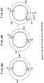
- FIG. 4a shows a case when the read pointer RP 8-2 is positioned at an address position R1 and the write pointer WP 8-1 is positioned at an address position W1.
- the clockwise direction of the ring buffer 4 in the figure is considered to be the direction of the normal reproduction and writing/reading is performed in this direction. Note that because the address position R1 and the address position W1 are positioned so as to almost face each other on the ring buffer 4, the sizes of an unread data area URD and an already-read data area ARD become almost equal.
- I picture I0 is read out of the ring buffer 4 again to be decoded and to be stored in the frame memory M2 (State 4).
- B picture B1 is read out of the ring buffer 4 to be decoded with reference to P1 and P0 frames and to be stored in the frame memory M1. It is then sent to the display 7 to display an image of B1 frame (State 5).
- B picture B0 is read out of the ring buffer 4 to be decoded similarly with reference to P1 and P0 frames and to be stored in the frame memory M1. It is sent to the display 7 to display its image (State 6).
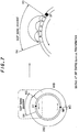
- FIG. 6b shows a state wherein the decoding has advanced to the next GOP. That is, the GOP stored in the area from the address position R4 to an address position R5 is being read out of the ring buffer 4 to be decoded. Because the unread data area becomes small in that state, the control circuit 8 controls the pickup 2 to return to read new data of the past from the disk 1. At the same time, it causes the write pointer WP to jump from the address position W3 to the address position W4 and writes the data read out of the disk 1 to the ring buffer 4 while moving the write pointer WP clockwise. In this case, the write pointer WP 8-1 is controlled so as to jump by an area into which a number of sectors which is the sum of a number of sectors written in the last time and a number of sectors to be written this time can be written.
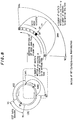
- FIG. 7 shows detailed motions of the read pointer RP during such reverse reproduction and FIG. 8 shows detailed motions of the write pointer WP.
- each decoded frame may be stored in the frame memories M1, M2 and M3 as shown in FIG. 3 through the motions of the read pointer RP and the write pointer WP.
- FIG. 7a is the same figure with FIG. 6a and a part surrounded by a broken line in the figure is enlarged and is shown as FIG. 7b.
- the read pointer RP jumps from the address position R3 to the address position R4 in the reproducing direction in decoding a GOP to read I picture at the head of the GOP.
- FIG. 8a shows the same state with that shown in FIG. 6c, wherein a part shown by a broken line is enlarged and is shown as FIG. 8b.
- the write pointer WP positioned at the address position W3 jumps to the address position W4 in writing data. It is the address position where data of a number of sectors of the sum of a number of sectors written in the last time and a number of sectors to be written this time may be written in the area from the address position W3 and the address position W4 as described before. Then, returning from the address position W4, the sectors S0, S1, S2, S3, S4, and S5 ... are written.
- variable-speed reproduction not only during the reverse reproduction but also during the normal reproduction.
- variable-speed reproduction mode it is possible to respond to the variable-speed reproduction such as a double-speed reproduction by reproducing only I pictures or only I pictures and P pictures.
- digital video data, digital audio data or the like is compressed and recorded in a disk (DV) 1 by means of the MPEG method or the like.
- a pickup 202 reads the recorded digital data from the disk 201, a demodulating circuit 203 demodulates the read digital data, an error correction circuit (ECC) 204 corrects errors using error correction codes, a buffer 205 is inserted to buffer a rate on the decoder side which differs from a rate on the reading side and a decoder 206 decodes and outputs the coded data into image signals to be displayed on a display unit (VIDEO OUT).
- ECC error correction circuit
- a system control 207 sends various control signals to a servo circuit 209 to control focus, tracking and threading, etc.
- control keys 208 are buttons such as reproduction button, stop button, double-speed reproduction button, reverse reproduction button operated by a user
- the servo circuit 209 controls the focus, tracking and threading of the pickup 202 under the control of the system control 207.
- the sector demodulated by the demodulating circuit 203 undergoes the ECC 204 for correction of its error. Its position where it is written is controlled from a detected sector address of the data and is written to the buffer 205.
- This buffer 205 is adapted to have a memory capacity capable of storing at least 2 GOPs of digital data. GOP data in the frame sequence shown in FIG. 10b is read sequentially out of the buffer 205 and I pictures, P pictures and B pictures composing the GOP are decoded by the decoder 206 to reproduce and output an image signal of each frame (VIDEO OUT).
- the video signals output from the decoder 206 (VIDEO OUT) are supplied to the display unit, reproducing the video images on the display unit.
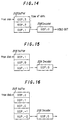
- GOP. 1 which follows GOP. 0 is read out of the buffer 205 and is supplied to the decoder 206. Then, the system control 207 controls the pickup 202 to access to the disk 201 and to read GOP. 4, new data to be stored in the buffer 205. The video signals are thus reproduced and displayed on the display unit one after another. Note that the rate at which the data is read out of the disk 201 is set to be faster than the rate at which the video signals are output from the decoder 206.
- the system control 207 puts the reproduction from the pickup 202 into a pause mode and when data stored in the buffer 205 becomes less, it puts to the reproduction mode to store data in the buffer 205.
- a ratio between a compressed coding amount before being decoded by the decoder 206 and a coding amount after the decoding is made to vary corresponding to a complexity and flatness of video signals as described before, because the rate of the video signals decoded and output is of generally a constant display speed, a rate of the amount of supply of the compressed coded signals input to the decoder 206 is made to be random corresponding to the complexity and flatness of the video signals in order for that the decoded and output video signals are continuous.
- FIG. 15 diagrammatically shows operations of the buffer 205 and the decoder 206 when the control key 208 is operated and a still mode is specified.
- the system control 207 controls the pickup 202 to access the disk 201 and to read GOP. 0 and GOP. -1 which precedes GOP. 0 time-wise and writes them to the buffer 205.
- the decoder 206 can read GOP. -1 out of the buffer 205, which is to be decoded immediately after finishing the decoding of the GOP. 0 being decoded.
Landscapes
- Engineering & Computer Science (AREA)
- Multimedia (AREA)
- Signal Processing (AREA)
- Signal Processing For Digital Recording And Reproducing (AREA)
- Television Signal Processing For Recording (AREA)
- Compression Or Coding Systems Of Tv Signals (AREA)
- Holo Graphy (AREA)
- Circuits Of Receivers In General (AREA)
- Radar Systems Or Details Thereof (AREA)
- Indexing, Searching, Synchronizing, And The Amount Of Synchronization Travel Of Record Carriers (AREA)
Priority Applications (1)
| Application Number | Priority Date | Filing Date | Title |
|---|---|---|---|
| EP00200563A EP1003339A1 (de) | 1994-09-05 | 1995-08-29 | Datenwiedergabe |
Applications Claiming Priority (6)
| Application Number | Priority Date | Filing Date | Title |
|---|---|---|---|
| JP23452494 | 1994-09-05 | ||
| JP234527/94 | 1994-09-05 | ||
| JP23452794 | 1994-09-05 | ||
| JP23452794A JP3248366B2 (ja) | 1994-09-05 | 1994-09-05 | データ再生方法およびデータ再生装置 |
| JP6234524A JPH0879702A (ja) | 1994-09-05 | 1994-09-05 | データ再生方法およびデータ再生装置 |
| JP234524/94 | 1994-09-05 |
Related Child Applications (1)
| Application Number | Title | Priority Date | Filing Date |
|---|---|---|---|
| EP00200563A Division EP1003339A1 (de) | 1994-09-05 | 1995-08-29 | Datenwiedergabe |
Publications (3)
| Publication Number | Publication Date |
|---|---|
| EP0700220A2 true EP0700220A2 (de) | 1996-03-06 |
| EP0700220A3 EP0700220A3 (de) | 1997-07-30 |
| EP0700220B1 EP0700220B1 (de) | 2001-08-08 |
Family
ID=26531614
Family Applications (2)
| Application Number | Title | Priority Date | Filing Date |
|---|---|---|---|
| EP95306006A Expired - Lifetime EP0700220B1 (de) | 1994-09-05 | 1995-08-29 | Datenwiedergabe |
| EP00200563A Withdrawn EP1003339A1 (de) | 1994-09-05 | 1995-08-29 | Datenwiedergabe |
Family Applications After (1)
| Application Number | Title | Priority Date | Filing Date |
|---|---|---|---|
| EP00200563A Withdrawn EP1003339A1 (de) | 1994-09-05 | 1995-08-29 | Datenwiedergabe |
Country Status (11)
| Country | Link |
|---|---|
| US (1) | US5771331A (de) |
| EP (2) | EP0700220B1 (de) |
| KR (1) | KR960011870A (de) |
| CN (1) | CN1079972C (de) |
| AT (1) | ATE204111T1 (de) |
| AU (1) | AU699861B2 (de) |
| BR (1) | BR9503861A (de) |
| CA (1) | CA2156463A1 (de) |
| DE (1) | DE69522059T2 (de) |
| MY (1) | MY112474A (de) |
| TW (1) | TW400514B (de) |
Cited By (2)
| Publication number | Priority date | Publication date | Assignee | Title |
|---|---|---|---|---|
| EP0789360A3 (de) * | 1996-02-09 | 1999-06-30 | Sony Corporation | Datenaufnahme und -wiedergabe |
| US6501901B2 (en) | 1997-01-23 | 2002-12-31 | Sony Corporation | Apparatus and method for performing an editing operation on data read-out from a storage medium which allows random access |
Families Citing this family (28)
| Publication number | Priority date | Publication date | Assignee | Title |
|---|---|---|---|---|
| US6009231A (en) * | 1994-09-05 | 1999-12-28 | Sony Corporation | Reproduction of information using a ring buffer with read and write pointers separated from each other by substantially half of the total ring buffer capacity |
| JP3491366B2 (ja) * | 1995-01-31 | 2004-01-26 | ソニー株式会社 | 符号化データの特殊再生方法および特殊再生装置 |
| US20030156525A1 (en) * | 1995-10-04 | 2003-08-21 | Bunsen Fan | Method of and system for block-by-block data retrieval for optical storage |
| KR0176141B1 (ko) * | 1996-06-25 | 1999-04-15 | 김광호 | 메모리 다중 영역 관리장치 및 방법 |
| JPH10135909A (ja) * | 1996-10-31 | 1998-05-22 | Sony Corp | 光信号送信装置、光信号受信装置、光信号伝送装置および光信号伝送方法 |
| US6208655B1 (en) | 1996-11-27 | 2001-03-27 | Sony Europa, B.V., | Method and apparatus for serving data |
| US6154603A (en) * | 1997-02-18 | 2000-11-28 | Thomson Licensing S.A. | Picture decoding for trick mode operation |
| JPH10322665A (ja) * | 1997-05-07 | 1998-12-04 | Lsi Logic Corp | Gopデータの反復読出し制御方法および装置 |
| DE19720651C2 (de) * | 1997-05-16 | 2001-07-12 | Siemens Audiologische Technik | Hörgerät mit verschiedenen Baugruppen zur Aufnahme, Weiterverarbeitung sowie Anpassung eines Schallsignals an das Hörvermögen eines Schwerhörigen |
| CA2305368C (en) | 1997-10-06 | 2006-01-03 | Dvdo, Inc. | Digital video system and methods for providing same |
| KR100556717B1 (ko) * | 1998-05-06 | 2006-03-10 | 톰슨 라이센싱 | 비트스트림 처리 장치 및 방법, 및 플레이어 |
| US5959932A (en) * | 1998-08-17 | 1999-09-28 | Emc Corporation | Method and apparatus for detecting errors in the writing of data to a memory |
| US6751400B1 (en) * | 1998-09-17 | 2004-06-15 | Sony Corporation | Reproducing method and apparatus |
| US6909469B2 (en) * | 1999-08-11 | 2005-06-21 | Silicon Image, Inc. | Interlace motion artifact detection using vertical frequency detection and analysis |
| KR100605893B1 (ko) * | 1999-10-08 | 2006-08-01 | 삼성전자주식회사 | 시간지연 시청을 위한 비디오 스트림 처리방법 |
| US6999386B2 (en) * | 2000-03-17 | 2006-02-14 | Matsushita Electric Industrial Co., Ltd. | Drive, method for reading data, information recording medium reproduction apparatus, and method for reproducing data having reading errors |
| US6867814B2 (en) * | 2000-04-18 | 2005-03-15 | Silicon Image, Inc. | Method, system and article of manufacture for identifying the source type and quality level of a video sequence |
| EP1374430A4 (de) * | 2001-03-05 | 2005-08-17 | Intervideo Inc | Systeme und verfahren zur fehlerbeständigen codierung |
| US6847779B2 (en) * | 2001-03-24 | 2005-01-25 | Microsoft Corporation | Rewind and fast-forward for enhanced television |
| US8958688B2 (en) | 2001-11-26 | 2015-02-17 | Nvidia Corporation | Method and system for DVD smooth rewind |
| US7221851B1 (en) | 2001-11-26 | 2007-05-22 | Nvidia Corporation | Method and system for DVD smooth search transitions |
| JP3951839B2 (ja) * | 2002-07-15 | 2007-08-01 | ソニー株式会社 | 画像データ再生装置及び方法 |
| FR2849332A1 (fr) | 2002-12-20 | 2004-06-25 | St Microelectronics Sa | Procede et dispositif et decodage et d'affichage en marche arriere d'images mpeg, circuit pilote video et boitier decodeur incorporant un tel dispositif |
| CN102469038B (zh) * | 2010-11-15 | 2014-11-05 | 阿里巴巴集团控股有限公司 | 文件夹传输方法及装置 |
| CN102355604B (zh) * | 2011-09-28 | 2013-10-09 | 北京华为数字技术有限公司 | 媒体报文传输方法及装置 |
| TWI666930B (zh) * | 2016-07-12 | 2019-07-21 | 聯發科技股份有限公司 | 一種使用環形緩衝器和競賽模式環形緩衝器訪問控制方案的視訊處理系統 |
| CN113271468A (zh) * | 2020-02-14 | 2021-08-17 | 北京灵汐科技有限公司 | 一种基于GOP的SoC视频解码缓冲方法和装置 |
| US12593074B2 (en) | 2024-05-20 | 2026-03-31 | Qualcomm Incorporated | Systems and methods of buffering image data between a pixel processor and an entropy coder |
Family Cites Families (6)
| Publication number | Priority date | Publication date | Assignee | Title |
|---|---|---|---|---|
| JPH0812743B2 (ja) * | 1983-06-30 | 1996-02-07 | 株式会社東芝 | ディスク装置 |
| GB2154825B (en) * | 1984-02-22 | 1987-06-17 | Sony Corp | Digital television signal processing apparatus |
| EP0289960B1 (de) * | 1987-04-30 | 1993-10-20 | Nec Corporation | Bildverarbeitungssystem für eine Folge kodierter Signale, die einer Prädiktionskodierung verschiedener Arten unterworfen sind |
| JPH04105284A (ja) * | 1990-08-24 | 1992-04-07 | Sony Corp | 光ディスク記録及び/又は再生装置 |
| JP3158370B2 (ja) * | 1991-07-12 | 2001-04-23 | ソニー株式会社 | ディスクデータ再生装置 |
| JP2559009B2 (ja) * | 1993-03-25 | 1996-11-27 | 松下電器産業株式会社 | 動画像信号記録装置及び動画像信号再生装置 |
-
1995
- 1995-08-18 CA CA002156463A patent/CA2156463A1/en not_active Abandoned
- 1995-08-25 MY MYPI95002526A patent/MY112474A/en unknown
- 1995-08-29 US US08/520,837 patent/US5771331A/en not_active Expired - Fee Related
- 1995-08-29 EP EP95306006A patent/EP0700220B1/de not_active Expired - Lifetime
- 1995-08-29 EP EP00200563A patent/EP1003339A1/de not_active Withdrawn
- 1995-08-29 DE DE69522059T patent/DE69522059T2/de not_active Expired - Fee Related
- 1995-08-29 AT AT95306006T patent/ATE204111T1/de not_active IP Right Cessation
- 1995-08-30 BR BR9503861A patent/BR9503861A/pt not_active Application Discontinuation
- 1995-09-01 TW TW084109160A patent/TW400514B/zh not_active IP Right Cessation
- 1995-09-04 AU AU30430/95A patent/AU699861B2/en not_active Ceased
- 1995-09-05 CN CN95116225A patent/CN1079972C/zh not_active Expired - Fee Related
- 1995-09-05 KR KR1019950029525A patent/KR960011870A/ko not_active Withdrawn
Non-Patent Citations (1)
| Title |
|---|
| None |
Cited By (2)
| Publication number | Priority date | Publication date | Assignee | Title |
|---|---|---|---|---|
| EP0789360A3 (de) * | 1996-02-09 | 1999-06-30 | Sony Corporation | Datenaufnahme und -wiedergabe |
| US6501901B2 (en) | 1997-01-23 | 2002-12-31 | Sony Corporation | Apparatus and method for performing an editing operation on data read-out from a storage medium which allows random access |
Also Published As
| Publication number | Publication date |
|---|---|
| TW400514B (en) | 2000-08-01 |
| CN1079972C (zh) | 2002-02-27 |
| AU3043095A (en) | 1996-03-21 |
| AU699861B2 (en) | 1998-12-17 |
| US5771331A (en) | 1998-06-23 |
| DE69522059D1 (de) | 2001-09-13 |
| EP1003339A1 (de) | 2000-05-24 |
| CN1139796A (zh) | 1997-01-08 |
| EP0700220B1 (de) | 2001-08-08 |
| KR960011870A (ko) | 1996-04-20 |
| ATE204111T1 (de) | 2001-08-15 |
| MY112474A (en) | 2001-06-30 |
| CA2156463A1 (en) | 1996-03-06 |
| DE69522059T2 (de) | 2002-03-21 |
| BR9503861A (pt) | 1996-09-17 |
| EP0700220A3 (de) | 1997-07-30 |
Similar Documents
| Publication | Publication Date | Title |
|---|---|---|
| EP0700220B1 (de) | Datenwiedergabe | |
| US6009231A (en) | Reproduction of information using a ring buffer with read and write pointers separated from each other by substantially half of the total ring buffer capacity | |
| JP3491366B2 (ja) | 符号化データの特殊再生方法および特殊再生装置 | |
| EP0700221B1 (de) | Datenwiedergabe | |
| JP4493338B2 (ja) | ビデオのセグメントをトリック・モードで再生する方法およびシステム | |
| KR100402188B1 (ko) | 압축인코딩된이미지데이터를재생하는방법및장치 | |
| US20060029364A1 (en) | Digital video stream trick play | |
| US5715354A (en) | Image data regenerating apparatus | |
| US5892882A (en) | Moving picture decoding device having a compressed picture data memory | |
| KR970050128A (ko) | 고속재생을 위한 비디오데이타 복호방법 및 그 장치 | |
| KR100274922B1 (ko) | 화상 표시 장치 및 그 특수 재생 제어 장치 | |
| KR100420892B1 (ko) | 데이터재생방법및재생장치 | |
| JP3093724B2 (ja) | 動画像データ再生装置及び動画像データの逆再生方法 | |
| JPWO1995002300A1 (ja) | 画像信号復号化方法及び画像信号復号化装置 | |
| JP2000083215A (ja) | 再生方法及び再生装置 | |
| JP3607315B2 (ja) | 動画像復号化装置 | |
| JP3248366B2 (ja) | データ再生方法およびデータ再生装置 | |
| AU711638B2 (en) | Data reproducing method and data reproducing apparatus | |
| JP3344607B2 (ja) | 光ディスク、再生装置および再生方法 | |
| JPH10322665A (ja) | Gopデータの反復読出し制御方法および装置 | |
| KR950010338B1 (ko) | 디지탈 동영상 고속 재생용 제어장치 | |
| KR20000035681A (ko) | 엠피이지 재생 장치 및 엠피이지 재생 방법 | |
| JP3507990B2 (ja) | 動画像再生装置及び動画像記録再生装置 | |
| JPH06339113A (ja) | 動画像記録再生装置 | |
| MXPA95003629A (en) | Method of data reproduction and da reproduction device |
Legal Events
| Date | Code | Title | Description |
|---|---|---|---|
| PUAI | Public reference made under article 153(3) epc to a published international application that has entered the european phase |
Free format text: ORIGINAL CODE: 0009012 |
|
| AK | Designated contracting states |
Kind code of ref document: A2 Designated state(s): AT DE FR GB IT NL |
|
| PUAL | Search report despatched |
Free format text: ORIGINAL CODE: 0009013 |
|
| AK | Designated contracting states |
Kind code of ref document: A3 Designated state(s): AT DE FR GB IT NL |
|
| 17P | Request for examination filed |
Effective date: 19980105 |
|
| 17Q | First examination report despatched |
Effective date: 19991007 |
|
| GRAG | Despatch of communication of intention to grant |
Free format text: ORIGINAL CODE: EPIDOS AGRA |
|
| GRAG | Despatch of communication of intention to grant |
Free format text: ORIGINAL CODE: EPIDOS AGRA |
|
| GRAH | Despatch of communication of intention to grant a patent |
Free format text: ORIGINAL CODE: EPIDOS IGRA |
|
| GRAH | Despatch of communication of intention to grant a patent |
Free format text: ORIGINAL CODE: EPIDOS IGRA |
|
| GRAA | (expected) grant |
Free format text: ORIGINAL CODE: 0009210 |
|
| AK | Designated contracting states |
Kind code of ref document: B1 Designated state(s): AT DE FR GB IT NL |
|
| REF | Corresponds to: |
Ref document number: 204111 Country of ref document: AT Date of ref document: 20010815 Kind code of ref document: T |
|
| PGFP | Annual fee paid to national office [announced via postgrant information from national office to epo] |
Ref country code: FR Payment date: 20010810 Year of fee payment: 7 |
|
| PGFP | Annual fee paid to national office [announced via postgrant information from national office to epo] |
Ref country code: AT Payment date: 20010813 Year of fee payment: 7 |
|
| PGFP | Annual fee paid to national office [announced via postgrant information from national office to epo] |
Ref country code: DE Payment date: 20010820 Year of fee payment: 7 |
|
| PGFP | Annual fee paid to national office [announced via postgrant information from national office to epo] |
Ref country code: NL Payment date: 20010830 Year of fee payment: 7 Ref country code: GB Payment date: 20010830 Year of fee payment: 7 |
|
| REF | Corresponds to: |
Ref document number: 69522059 Country of ref document: DE Date of ref document: 20010913 |
|
| ET | Fr: translation filed | ||
| REG | Reference to a national code |
Ref country code: GB Ref legal event code: IF02 |
|
| PLBE | No opposition filed within time limit |
Free format text: ORIGINAL CODE: 0009261 |
|
| STAA | Information on the status of an ep patent application or granted ep patent |
Free format text: STATUS: NO OPPOSITION FILED WITHIN TIME LIMIT |
|
| 26N | No opposition filed | ||
| PG25 | Lapsed in a contracting state [announced via postgrant information from national office to epo] |
Ref country code: GB Free format text: LAPSE BECAUSE OF NON-PAYMENT OF DUE FEES Effective date: 20020829 Ref country code: AT Free format text: LAPSE BECAUSE OF NON-PAYMENT OF DUE FEES Effective date: 20020829 |
|
| PG25 | Lapsed in a contracting state [announced via postgrant information from national office to epo] |
Ref country code: NL Free format text: LAPSE BECAUSE OF NON-PAYMENT OF DUE FEES Effective date: 20030301 Ref country code: DE Free format text: LAPSE BECAUSE OF NON-PAYMENT OF DUE FEES Effective date: 20030301 |
|
| GBPC | Gb: european patent ceased through non-payment of renewal fee |
Effective date: 20020829 |
|
| PG25 | Lapsed in a contracting state [announced via postgrant information from national office to epo] |
Ref country code: FR Free format text: LAPSE BECAUSE OF NON-PAYMENT OF DUE FEES Effective date: 20030430 |
|
| NLV4 | Nl: lapsed or anulled due to non-payment of the annual fee |
Effective date: 20030301 |
|
| REG | Reference to a national code |
Ref country code: FR Ref legal event code: ST |
|
| PG25 | Lapsed in a contracting state [announced via postgrant information from national office to epo] |
Ref country code: IT Free format text: LAPSE BECAUSE OF NON-PAYMENT OF DUE FEES Effective date: 20050829 |