EP0700620B1 - Dispositif audiovisuel et systeme dans lequel ce dernier est utilise - Google Patents
Dispositif audiovisuel et systeme dans lequel ce dernier est utilise Download PDFInfo
- Publication number
- EP0700620B1 EP0700620B1 EP95910697A EP95910697A EP0700620B1 EP 0700620 B1 EP0700620 B1 EP 0700620B1 EP 95910697 A EP95910697 A EP 95910697A EP 95910697 A EP95910697 A EP 95910697A EP 0700620 B1 EP0700620 B1 EP 0700620B1
- Authority
- EP
- European Patent Office
- Prior art keywords
- audio
- signal
- converters
- acoustic
- arrangement
- Prior art date
- Legal status (The legal status is an assumption and is not a legal conclusion. Google has not performed a legal analysis and makes no representation as to the accuracy of the status listed.)
- Expired - Lifetime
Links
Images


Classifications
-
- G—PHYSICS
- G06—COMPUTING OR CALCULATING; COUNTING
- G06F—ELECTRIC DIGITAL DATA PROCESSING
- G06F1/00—Details not covered by groups G06F3/00 - G06F13/00 and G06F21/00
- G06F1/16—Constructional details or arrangements
- G06F1/1601—Constructional details related to the housing of computer displays, e.g. of CRT monitors, of flat displays
- G06F1/1605—Multimedia displays, e.g. with integrated or attached speakers, cameras, microphones
-
- G—PHYSICS
- G06—COMPUTING OR CALCULATING; COUNTING
- G06F—ELECTRIC DIGITAL DATA PROCESSING
- G06F3/00—Input arrangements for transferring data to be processed into a form capable of being handled by the computer; Output arrangements for transferring data from processing unit to output unit, e.g. interface arrangements
- G06F3/16—Sound input; Sound output
- G06F3/165—Management of the audio stream, e.g. setting of volume, audio stream path
-
- H—ELECTRICITY
- H04—ELECTRIC COMMUNICATION TECHNIQUE
- H04N—PICTORIAL COMMUNICATION, e.g. TELEVISION
- H04N5/00—Details of television systems
- H04N5/64—Constructional details of receivers, e.g. cabinets or dust covers
- H04N5/642—Disposition of sound reproducers
-
- H—ELECTRICITY
- H04—ELECTRIC COMMUNICATION TECHNIQUE
- H04R—LOUDSPEAKERS, MICROPHONES, GRAMOPHONE PICK-UPS OR LIKE ACOUSTIC ELECTROMECHANICAL TRANSDUCERS; ELECTRIC HEARING AIDS; PUBLIC ADDRESS SYSTEMS
- H04R5/00—Stereophonic arrangements
- H04R5/02—Spatial or constructional arrangements of loudspeakers
Definitions
- the invention relates to an audio-visual arrangement as described in the preamble of claim 1.
- Such audio-visual arrangements comprise the so-called multi-media systems.
- a known multi-media system is the CD-I system described, for example, in the title “COMPACT DISC-INTERACTIVE; A DESIGNER'S OVERVIEW” (IBN-90 201 2121 9).
- Such systems are often used in an environment in which not only the user of the multi-media system but also other persons are present. In this context one may think of the members of a family who are present in the same living room as the user of the multi-media system, or colleagues who are present in the same office space as the user of the multi-media system. These other persons are generally not interested in the sound produced by the multi-media system and will often experience this sound as annoying.
- French patent application FR-A-2649572 describes an arrangement for reproducing sound of a television receiver using at the left and at the right means to provide optimal sound in a horizontal plane perpendicular to the screen at a height corresponding to the expected viewing and listening height of the user.
- the described invention in D 1 relates to improving the perceived sound reproduction of large TV screens.
- An embodiment for the audio-visual arrangement is characterized in that in a predetermined user orientation of the arrangement the pictures are displayed in upright position on the screen, in that the predetermined user orientation at least a plurality of converters are uniformly interspaced along the top and/or bottom of the picture screen.
- a further embodiment for the audio-visual arrangement is characterized in that for the predetermined user orientation at least a number of converters are positioned uniformly interspaced along a left and/or right-hand side of the picture screen.
- a further embodiment for the audio-visual arrangement is characterized in that the positions of converters along two mutually opposite sides of the picture screen are mutually shifted over a distance substantially equal to half the distance between two consecutive converters positioned on the same side of the picture screen.
- An annoyance caused by the produced sound and experienced by the persons other than the user may be further reduced by the extension by an additional electro-acoustic converter and a signal processor which is coupled to the audio-visual means for receiving an audio input signal that corresponds to the sound reproduced by the audio-visual arrangement, which signal processor is further coupled to the acousto-electric converter for receiving a measuring signal that corresponds to sound received by the acousto-electric converter, and which signal processor is coupled to the additional converter for supplying a compensation signal to the additional electro-acoustic converter, and the signal processor comprises signal processing means for deriving the compensation signal in response to the audio signal and the measuring signal so as to reduce the presence of signal components of the first audio signal in the measuring signal.
- this embodiment reduces the perceivable sound volume outside the listening and viewing area for the medium and high frequencies. For low frequencies this concentration is less effective. In this embodiment the perceptibility of the low frequencies is largely combatted by active noise abatement.
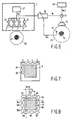
- Fig. 1 shows an embodiment for an audio-visual arrangement 1 according to the invention, for example, in the form of a multi-media personal computer.
- the arrangement 1 comprises a picture screen 6 on which a picture can be visualized by playback means (not shown) of a customary type.
- the arrangement comprises a plurality of electro-acoustic converters 2, 3, 4 and 5 of a customary type.
- the converters 2, 3, 4 and 5 are positioned on one side of the picture screen.
- the converters are controlled by control signals, while the ratios between the control signal strengths have values at which a concentration of soundwaves is obtained in a listening and viewing area that is situated substantially dead opposite to the picture screen 6.
- Fig. 2 shows an embodiment for a control circuit 20 for generating control signals for the converters 2, 3, 4 and 5.
- the control circuit comprises an audio signal source 21 of a customary type, which generates an audio signal that represents the audio information to be reproduced.
- the audio signal generated by the audio signal source is supplied to the electro-acoustic converters 2, 3, 4 and 5 through filters 22, 23, 24 and 25.
- the concentration characteristics are frequency-dependent, which means that for an optimum concentration the mutual ratios between the control signal strengths are different for different frequencies.
- the mutual strength differences can be optimized for each frequency.
- Fig. 3 shows a line of four identical converters 32, 33, 34 and 35 having constant relative distances equal to d, where d is equal to 0.266 m.
- the control signal strength for the outside two converters 32 and 35 is for all frequencies twice as large as the control signal strength for the inside two converters 33 and 34.
- a manner in which this control signal strength ratio may be obtained is shown in Fig. 5.
- the same control voltage Vs is applied to the converters 32 and 35 as to a series combination of converters 33 and 34.
- the impedance of the series combination of the converters 33 and 34 is equal to twice the impedance of the converter 32 or 35, leading to the fact that the control signal strength for the converters 33 and 34 is half the strength of the control signal for the converters 32 and 35.
- Fig. 4 shows the radiation pattern belonging to the configuration shown in Fig. 3 and Fig. 5.
- the curves 40, 41 and 42 show the radiation characteristic for the frequencies 866 Hz, 1225 Hz and 1732 Hz, respectively. As appears from Fig. 4 the sound is concentrated in an area dead opposite to the line of converters 32, 33, 34 and 35.
- the concentration of soundwaves diminishes for lower frequencies. For these lower frequencies it is possible to realise a better concentration by increasing the overall length of the line of converters.
- the room available for the line of converters is limited to a length that is of the same order of magnitude as the width of the picture screen.
- Fig. 6 shows an embodiment for a system comprising the audio-visual arrangement 1.
- the audio signal source 21 present in the arrangement 1 generates an audio signal Va1 which is representative of the audio information Va1 intended for a user 63 in a listening and viewing area 62.
- This signal Va1 is applied with different strengths to a line of converters 2, 3, 4 and 5, so that a concentration of the sound in the listening/viewing area 62 is obtained.
- the audio signal source 69 generates an audio signal Va2 which is applied, via an adder circuit 71, to an electro-acoustic converter 70 for making the audio information Va2 audible.
- an acousto-electric converter 75 for example, in the form of a microphone of a customary type, which produces a measuring signal Vm that corresponds to the sound received by the converter 75.
- the measuring signal Vm produced by the acousto-electric converter 75 is applied to a signal processor 76. Also the audio signal Va1 is applied to the signal processor 76.
- the signal processor 76 applies a compensation signal Vc to the adder circuit 71, which adds this compensation signal to the audio signal Va2 received from the audio signal source 69.
- the signal processor 76 is of a type deriving the compensation signal Vc from the signal Va1 according to a customary criterion, so that the component of the signal Va1 in the measuring signal Vm is reduced as a result of the strength of the compensation signal Vc. Worded differently, the sound in the area 72 coming from the converters 2, ..., 5 is compensated for by applying signal components of the audio signal Va1 to the converter 76.
- the perceptible sound volume in the area 72 is reduced by a concentration of the audio-signal-Val-equivalent sound in the listening and viewing area 62.
- the signal processor 76 By applying active noise abatement by means of the signal processor 76, the sound volume in the area 72 caused by the converters 2, ... 5 is reduced even more.
- the concentration of low frequency components in the sound produced by the converters 2, ... 5 is less effective, it is preferable during noise abatement to emphasize the compensation for the low frequency noise. This may be realised by using, in essence, low frequency components of the signal Va1 for the active noise abatement.
- a compensation for the sound coming from the converters 2, ..., 5 is realised in the area 72. It will be obvious to a person skilled in the art that it is similarly possible to realise in the area 62 a compensation for the sound produced by the converter 70. It is also possible to utilize a line of converters in lieu of a single converter 70, by which line a concentration of the sound in the area 72 is realised.
- FIG. 7 A first embodiment for an audio-visual arrangement in which the sound is concentrated in both the horizontal and the vertical plane is shown in Fig. 7.
- a line of two electro-acoustic converters 86 and 87 installed above one another are installed on one side of the picture screen, the left-hand side in Fig. 7, to concentrate the sound in the vertical plane.
- Fig. 8 shows a different array of converters by which also a concentration in the horizontal and vertical planes is obtained.
- the converters are installed around the screen 6.
- the converters are positioned in two lines along opposite sides of the picture screen, mutually shifted in the direction of the line over a distance 1/2.d which is equal to half the distance d between the centres of consecutive converters in the line.
- This shift reduces the distance between the converters of two oppositely arranged lines, seen in the direction of each line.
- a smaller distance between the converters is advantageous in that a better concentration is obtained for high frequencies.
- the picture screen 6 operates as a sound board.
- the picture screen is then also one of the important factors determining the sound image in the space in which the audio-visual arrangement is installed.
- the position of the picture screen relative to the converters is fixed. Due to the fact that the picture screen has an important, space-independent, effect on the sound image, the influence of the space-dependent factors on the sound image has relatively diminished.
Landscapes
- Engineering & Computer Science (AREA)
- Theoretical Computer Science (AREA)
- Physics & Mathematics (AREA)
- Multimedia (AREA)
- General Engineering & Computer Science (AREA)
- General Physics & Mathematics (AREA)
- Human Computer Interaction (AREA)
- Signal Processing (AREA)
- Computer Hardware Design (AREA)
- Health & Medical Sciences (AREA)
- Audiology, Speech & Language Pathology (AREA)
- General Health & Medical Sciences (AREA)
- Acoustics & Sound (AREA)
- Stereophonic System (AREA)
- Circuit For Audible Band Transducer (AREA)
Abstract
Claims (9)
- Dispositif audiovisuel (1) comportantcaractérisé en ce que les moyens électroacoustiques comportent un réseau linéaire d'au moins quatre convertisseurs électroacoustiques (2, 3, 4, 5) qui sont installés dans sensiblement le même plan que l'écran ou dans un plan sensiblement parallèle au plan de l'écran (6) pour concentrer des ondes sonores dans une région d'écoute et de vision sensiblement en face de l'écran d'image où lesdits moyens pour générer des signaux de commande sont agencés de manière à exciter les convertisseurs électroacoustiques et où lesdits signaux de commande sont tels de façon que leurs intensités de signal augmentent en proportion de la distance à partir du centre du réseau électroacoustique.un écran d'image (6),des moyens pour effectuer qu'une image est affichée sur l'écran d'image,des moyens pour générer des signaux de commande (20),des moyens électroacoustiques (2, 3, 4, 5) pour générer des ondes sonores en réponse à des signaux de commande, etune source de signal audio (21) pour appliquer des signaux de commande aux moyens électroacoustiques,
- Dispositif audiovisuel selon la revendication 1, caractérisé en ce que dans une orientation utilisateur prédéterminée du dispositif les images sont affichées sur l'écran dans une position verticale du fait que dans le cas de l'orientation utilisateur prédéterminée au moins une pluralité de convertisseurs sont d'une manière uniforme espacés mutuellement le long du côté supérieur et/ou du côté inférieur de l'écran d'image.
- Dispositif audiovisuel selon la revendication 2, caractérisé en ce que pour l'orientation utilisateur prédéterminée au moins un certain nombre de convertisseurs sont d'une manière uniforme espacés mutuellement le long d'un côté gauche et/ou d'un côté droit de l'écran d'image.
- Dispositif audiovisuel selon la revendication 2 ou 3, caractérisé en ce que les convertisseurs le long de deux côtés sont mutuellement opposés (91, 92, 93 respectivement 97, 98, 99; 94, 95, 96 respectivement 100, 101, 102) mutuellement décalés sur une distance sensiblement égale à la moitié de la distance comprise entre deux convertisseurs consécutifs qui sont positionnés du même côté de l'écran d'image.
- Dispositif audiovisuel selon l'une quelconque des revendications précédentes 1 à 4, caractérisé en ce que le nombre de convertisseurs qui sont positionnés le long d'au moins un des côtés est égal à 4.
- Dispositif audiovisuel selon la revendication 4, caractérisé en ce que le rapport entre l'intensité des signaux de commande pour les deux convertisseurs extérieurs et l'intensité des signaux de commande pour les deux convertisseurs intérieurs est égal à 2.
- Système comportant un dispositif audiovisuel 1 selon l'une quelconque des revendications précédentes 1 à 6, au moins un convertisseur électroacoustique additionnel unique et un processeur de signal (76) qui est couplé aux moyens audiovisuels pour recevoir un signal d'entrée audio (Val) qui correspond au son étant reproduit par le dispositif audiovisuel, ledit processeur de signal étant encore couplé au convertisseur électroacoustique (75) pour recevoir un signal de mesure (Vm) qui correspond au son étant reçu par le convertisseur électroacoustique (75), ledit processeur de signal étant couplé au convertisseur additionnel pour appliquer un signal de compensation au convertisseur électroacoustique additionnel, et le processeur de signal (76) comporte des moyens de traitement de signal pour dériver le signal de compensation en réponse au signal audio et au signal de mesure de manière à réduire la présence, dans le signal de mesure, de composantes de signal du premier signal audio.
- Système selon la revendication 7, caractérisé en ce que les moyens de traitement de signal sont agencés de manière à réduire la présence de composantes de signal qui présentent des fréquences situées dans la gamme de basses fréquences du spectre d'audiofréquences.
- Système selon la revendication 7 ou 8, caractérisé en ce que le système comporte une nouvelle autre source de signal audio pour appliquer un signal de commande additionnel au convertisseur additionnel pour la reproduction sonore du son qui correspond au signal audio additionnel.
Priority Applications (1)
| Application Number | Priority Date | Filing Date | Title |
|---|---|---|---|
| EP95910697A EP0700620B1 (fr) | 1994-03-24 | 1995-03-17 | Dispositif audiovisuel et systeme dans lequel ce dernier est utilise |
Applications Claiming Priority (4)
| Application Number | Priority Date | Filing Date | Title |
|---|---|---|---|
| EP94200763 | 1994-03-24 | ||
| EP94200763 | 1994-03-24 | ||
| PCT/IB1995/000178 WO1995026102A1 (fr) | 1994-03-24 | 1995-03-17 | Dispositif audiovisuel et systeme dans lequel ce dernier est utilise |
| EP95910697A EP0700620B1 (fr) | 1994-03-24 | 1995-03-17 | Dispositif audiovisuel et systeme dans lequel ce dernier est utilise |
Publications (2)
| Publication Number | Publication Date |
|---|---|
| EP0700620A1 EP0700620A1 (fr) | 1996-03-13 |
| EP0700620B1 true EP0700620B1 (fr) | 2001-10-17 |
Family
ID=8216731
Family Applications (1)
| Application Number | Title | Priority Date | Filing Date |
|---|---|---|---|
| EP95910697A Expired - Lifetime EP0700620B1 (fr) | 1994-03-24 | 1995-03-17 | Dispositif audiovisuel et systeme dans lequel ce dernier est utilise |
Country Status (5)
| Country | Link |
|---|---|
| US (1) | US5724430A (fr) |
| EP (1) | EP0700620B1 (fr) |
| JP (1) | JP3795915B2 (fr) |
| DE (1) | DE69523243T2 (fr) |
| WO (1) | WO1995026102A1 (fr) |
Families Citing this family (6)
| Publication number | Priority date | Publication date | Assignee | Title |
|---|---|---|---|---|
| FI97576C (fi) * | 1995-03-17 | 1997-01-10 | Farm Film Oy | Äänentoistojärjestelmä |
| DE19542147A1 (de) * | 1995-11-11 | 1997-05-15 | Deutsche Telekom Ag | Verfahren zur lokalen Verknüpfung von optischen und akustischen Signalen |
| WO1998054926A1 (fr) * | 1997-05-28 | 1998-12-03 | Bauck Jerald L | Enceinte acoustique permettant d'amplifier le point ideal |
| JP4127156B2 (ja) * | 2003-08-08 | 2008-07-30 | ヤマハ株式会社 | オーディオ再生装置、ラインアレイスピーカユニットおよびオーディオ再生方法 |
| EP4340390A1 (fr) * | 2022-09-13 | 2024-03-20 | Pascal A/S | Haut-parleur a largeur de faisceau constante |
| US20260052336A1 (en) * | 2022-08-10 | 2026-02-19 | Pascal A/S | A constant beamwidth loudspeaker |
Family Cites Families (13)
| Publication number | Priority date | Publication date | Assignee | Title |
|---|---|---|---|---|
| BE756400A (fr) * | 1969-11-26 | 1971-03-01 | Elektroakusztikai Gyar | Enceinte acoustique |
| JPH0740199B2 (ja) * | 1979-08-16 | 1995-05-01 | チャプリン パテンツ ホ−ルディング カンパニ− インコ−ポレ−テッド | 繰り返し振動の相殺の方法 |
| US4311874A (en) * | 1979-12-17 | 1982-01-19 | Bell Telephone Laboratories, Incorporated | Teleconference microphone arrays |
| NL8001119A (nl) * | 1980-02-25 | 1981-09-16 | Philips Nv | Richtingsonafhankelijk luidsprekerszuil- of vlak. |
| JPS5768991A (en) * | 1980-10-16 | 1982-04-27 | Pioneer Electronic Corp | Speaker system |
| US4421957A (en) * | 1981-06-15 | 1983-12-20 | Bell Telephone Laboratories, Incorporated | End-fire microphone and loudspeaker structures |
| US4683590A (en) * | 1985-03-18 | 1987-07-28 | Nippon Telegraph And Telphone Corporation | Inverse control system |
| SE8704162D0 (sv) * | 1987-10-26 | 1987-10-26 | Jan Neslund | Anordning i samlingslokal |
| KR910007182B1 (ko) * | 1987-12-21 | 1991-09-19 | 마쯔시다덴기산교 가부시기가이샤 | 스크리인장치 |
| FR2649572B1 (fr) * | 1989-07-07 | 1991-09-20 | Thomson Consumer Electronics | Dispositif de reproduction sonore pour televiseurs |
| US5381485A (en) * | 1992-08-29 | 1995-01-10 | Adaptive Control Limited | Active sound control systems and sound reproduction systems |
| FR2699205B1 (fr) * | 1992-12-11 | 1995-03-10 | Decaux Jean Claude | Perfectionnements aux procédés et dispositifs pour protéger des bruits extérieurs un volume donné, de préférence disposé à l'intérieur d'un local. |
| JPH06332474A (ja) * | 1993-05-25 | 1994-12-02 | Matsushita Electric Ind Co Ltd | 騒音消去装置 |
-
1995
- 1995-03-17 EP EP95910697A patent/EP0700620B1/fr not_active Expired - Lifetime
- 1995-03-17 WO PCT/IB1995/000178 patent/WO1995026102A1/fr not_active Ceased
- 1995-03-17 DE DE69523243T patent/DE69523243T2/de not_active Expired - Lifetime
- 1995-03-17 JP JP52451895A patent/JP3795915B2/ja not_active Expired - Fee Related
-
1996
- 1996-11-12 US US08/748,118 patent/US5724430A/en not_active Expired - Lifetime
Also Published As
| Publication number | Publication date |
|---|---|
| DE69523243D1 (de) | 2001-11-22 |
| DE69523243T2 (de) | 2002-07-11 |
| JPH08511396A (ja) | 1996-11-26 |
| US5724430A (en) | 1998-03-03 |
| WO1995026102A1 (fr) | 1995-09-28 |
| EP0700620A1 (fr) | 1996-03-13 |
| JP3795915B2 (ja) | 2006-07-12 |
Similar Documents
| Publication | Publication Date | Title |
|---|---|---|
| US5784468A (en) | Spatial enhancement speaker systems and methods for spatially enhanced sound reproduction | |
| EP0476790B1 (fr) | Système de rehaussement d'effet stéréo | |
| US5027403A (en) | Video sound | |
| US8538036B2 (en) | Directed acoustic sound system | |
| US6169806B1 (en) | Computer, computer system and desk-top theater system | |
| US5530760A (en) | Apparatus and method for adjusting levels between channels of a sound system | |
| US10645521B2 (en) | Stereo and filter control for multi-speaker device | |
| JPH05219600A (ja) | ステレオ強調および指向性サーボを備えたオージオサラウンドシステム | |
| US4410761A (en) | Stereo loudspeaker system for a picture reproducing screen | |
| US8553914B2 (en) | Apparatus for reproduction of stereo sound | |
| EP0700620B1 (fr) | Dispositif audiovisuel et systeme dans lequel ce dernier est utilise | |
| JPH06178379A (ja) | 映像視聴システム | |
| US5113447A (en) | Method and system for optimizing audio imaging in an automotive listening environment | |
| EP0370619A2 (fr) | Système de son à plusieurs haut-parleurs pour un dispositif d'affichage vidéo | |
| CA1175361A (fr) | Synthetiseur de sons stereophoniques a phase auxiliaire | |
| JP2722788B2 (ja) | スピーカシステム | |
| JP3831984B2 (ja) | シートオーディオ装置 | |
| US20220095054A1 (en) | Sound output apparatus and sound output method | |
| JPS603297A (ja) | 小型ステレオ装置用可変指向性スピ−カ | |
| JP3262679B2 (ja) | センターチャンネル信号再生用スピーカ装置 | |
| JPS613600A (ja) | 映像再生装置のステレオスピ−カ装置 | |
| JPH0937384A (ja) | 多チャンネル音声再生装置 | |
| US5742691A (en) | Surround sound converter | |
| JP3317356B2 (ja) | テレビジョン受像機 | |
| JP3521641B2 (ja) | スピーカシステム |
Legal Events
| Date | Code | Title | Description |
|---|---|---|---|
| PUAI | Public reference made under article 153(3) epc to a published international application that has entered the european phase |
Free format text: ORIGINAL CODE: 0009012 |
|
| AK | Designated contracting states |
Kind code of ref document: A1 Designated state(s): DE FR GB |
|
| 17P | Request for examination filed |
Effective date: 19960328 |
|
| 17Q | First examination report despatched |
Effective date: 19971219 |
|
| GRAG | Despatch of communication of intention to grant |
Free format text: ORIGINAL CODE: EPIDOS AGRA |
|
| GRAG | Despatch of communication of intention to grant |
Free format text: ORIGINAL CODE: EPIDOS AGRA |
|
| GRAH | Despatch of communication of intention to grant a patent |
Free format text: ORIGINAL CODE: EPIDOS IGRA |
|
| GRAH | Despatch of communication of intention to grant a patent |
Free format text: ORIGINAL CODE: EPIDOS IGRA |
|
| GRAA | (expected) grant |
Free format text: ORIGINAL CODE: 0009210 |
|
| AK | Designated contracting states |
Kind code of ref document: B1 Designated state(s): DE FR GB |
|
| REF | Corresponds to: |
Ref document number: 69523243 Country of ref document: DE Date of ref document: 20011122 |
|
| REG | Reference to a national code |
Ref country code: GB Ref legal event code: IF02 |
|
| ET | Fr: translation filed | ||
| PLBE | No opposition filed within time limit |
Free format text: ORIGINAL CODE: 0009261 |
|
| STAA | Information on the status of an ep patent application or granted ep patent |
Free format text: STATUS: NO OPPOSITION FILED WITHIN TIME LIMIT |
|
| 26N | No opposition filed | ||
| REG | Reference to a national code |
Ref country code: GB Ref legal event code: 746 Effective date: 20021017 |
|
| REG | Reference to a national code |
Ref country code: FR Ref legal event code: D6 |
|
| PGFP | Annual fee paid to national office [announced via postgrant information from national office to epo] |
Ref country code: GB Payment date: 20110331 Year of fee payment: 17 Ref country code: FR Payment date: 20110414 Year of fee payment: 17 |
|
| PGFP | Annual fee paid to national office [announced via postgrant information from national office to epo] |
Ref country code: DE Payment date: 20110526 Year of fee payment: 17 |
|
| GBPC | Gb: european patent ceased through non-payment of renewal fee |
Effective date: 20120317 |
|
| REG | Reference to a national code |
Ref country code: FR Ref legal event code: ST Effective date: 20121130 |
|
| REG | Reference to a national code |
Ref country code: DE Ref legal event code: R119 Ref document number: 69523243 Country of ref document: DE Effective date: 20121002 |
|
| PG25 | Lapsed in a contracting state [announced via postgrant information from national office to epo] |
Ref country code: FR Free format text: LAPSE BECAUSE OF NON-PAYMENT OF DUE FEES Effective date: 20120402 Ref country code: GB Free format text: LAPSE BECAUSE OF NON-PAYMENT OF DUE FEES Effective date: 20120317 |
|
| PG25 | Lapsed in a contracting state [announced via postgrant information from national office to epo] |
Ref country code: DE Free format text: LAPSE BECAUSE OF NON-PAYMENT OF DUE FEES Effective date: 20121002 |