EP0700663B1 - Maschinenangetriebenes chirugisches Gerät für Arthroskopie mit Absaugrohr - Google Patents
Maschinenangetriebenes chirugisches Gerät für Arthroskopie mit Absaugrohr Download PDFInfo
- Publication number
- EP0700663B1 EP0700663B1 EP95202448A EP95202448A EP0700663B1 EP 0700663 B1 EP0700663 B1 EP 0700663B1 EP 95202448 A EP95202448 A EP 95202448A EP 95202448 A EP95202448 A EP 95202448A EP 0700663 B1 EP0700663 B1 EP 0700663B1
- Authority
- EP
- European Patent Office
- Prior art keywords
- collet
- locking
- locking plate
- housing
- tool
- Prior art date
- Legal status (The legal status is an assumption and is not a legal conclusion. Google has not performed a legal analysis and makes no representation as to the accuracy of the status listed.)
- Expired - Lifetime
Links
- 239000000463 material Substances 0.000 description 7
- 238000001356 surgical procedure Methods 0.000 description 7
- 230000007246 mechanism Effects 0.000 description 6
- 238000000034 method Methods 0.000 description 6
- 238000004519 manufacturing process Methods 0.000 description 3
- 238000012976 endoscopic surgical procedure Methods 0.000 description 2
- 238000001125 extrusion Methods 0.000 description 2
- 238000002355 open surgical procedure Methods 0.000 description 2
- XAGFODPZIPBFFR-UHFFFAOYSA-N aluminium Chemical compound [Al] XAGFODPZIPBFFR-UHFFFAOYSA-N 0.000 description 1
- 229910052782 aluminium Inorganic materials 0.000 description 1
- 230000001627 detrimental effect Effects 0.000 description 1
- 238000002674 endoscopic surgery Methods 0.000 description 1
- 239000012530 fluid Substances 0.000 description 1
Images



Classifications
-
- A—HUMAN NECESSITIES
- A61—MEDICAL OR VETERINARY SCIENCE; HYGIENE
- A61B—DIAGNOSIS; SURGERY; IDENTIFICATION
- A61B17/00—Surgical instruments, devices or methods
- A61B17/32—Surgical cutting instruments
- A61B17/320016—Endoscopic cutting instruments, e.g. arthroscopes, resectoscopes
- A61B17/32002—Endoscopic cutting instruments, e.g. arthroscopes, resectoscopes with continuously rotating, oscillating or reciprocating cutting instruments
-
- A—HUMAN NECESSITIES
- A61—MEDICAL OR VETERINARY SCIENCE; HYGIENE
- A61M—DEVICES FOR INTRODUCING MEDIA INTO, OR ONTO, THE BODY; DEVICES FOR TRANSDUCING BODY MEDIA OR FOR TAKING MEDIA FROM THE BODY; DEVICES FOR PRODUCING OR ENDING SLEEP OR STUPOR
- A61M1/00—Suction or pumping devices for medical purposes; Devices for carrying-off, for treatment of, or for carrying-over, body-liquids; Drainage systems
- A61M1/71—Suction drainage systems
- A61M1/74—Suction control
- A61M1/741—Suction control with means for varying suction manually
- A61M1/7413—Suction control with means for varying suction manually by changing the cross-section of the line
-
- A—HUMAN NECESSITIES
- A61—MEDICAL OR VETERINARY SCIENCE; HYGIENE
- A61B—DIAGNOSIS; SURGERY; IDENTIFICATION
- A61B17/00—Surgical instruments, devices or methods
- A61B2017/0042—Surgical instruments, devices or methods with special provisions for gripping
- A61B2017/00455—Orientation indicators, e.g. recess on the handle
-
- A—HUMAN NECESSITIES
- A61—MEDICAL OR VETERINARY SCIENCE; HYGIENE
- A61B—DIAGNOSIS; SURGERY; IDENTIFICATION
- A61B17/00—Surgical instruments, devices or methods
- A61B2017/00477—Coupling
-
- A—HUMAN NECESSITIES
- A61—MEDICAL OR VETERINARY SCIENCE; HYGIENE
- A61B—DIAGNOSIS; SURGERY; IDENTIFICATION
- A61B17/00—Surgical instruments, devices or methods
- A61B2017/00477—Coupling
- A61B2017/00482—Coupling with a code
-
- A—HUMAN NECESSITIES
- A61—MEDICAL OR VETERINARY SCIENCE; HYGIENE
- A61B—DIAGNOSIS; SURGERY; IDENTIFICATION
- A61B17/00—Surgical instruments, devices or methods
- A61B17/28—Surgical forceps
- A61B17/2812—Surgical forceps with a single pivotal connection
- A61B17/2833—Locking means
- A61B2017/2837—Locking means with a locking ratchet
-
- A—HUMAN NECESSITIES
- A61—MEDICAL OR VETERINARY SCIENCE; HYGIENE
- A61B—DIAGNOSIS; SURGERY; IDENTIFICATION
- A61B17/00—Surgical instruments, devices or methods
- A61B17/28—Surgical forceps
- A61B17/29—Forceps for use in minimally invasive surgery
- A61B2017/2926—Details of heads or jaws
- A61B2017/2927—Details of heads or jaws the angular position of the head being adjustable with respect to the shaft
- A61B2017/2929—Details of heads or jaws the angular position of the head being adjustable with respect to the shaft with a head rotatable about the longitudinal axis of the shaft
-
- A—HUMAN NECESSITIES
- A61—MEDICAL OR VETERINARY SCIENCE; HYGIENE
- A61M—DEVICES FOR INTRODUCING MEDIA INTO, OR ONTO, THE BODY; DEVICES FOR TRANSDUCING BODY MEDIA OR FOR TAKING MEDIA FROM THE BODY; DEVICES FOR PRODUCING OR ENDING SLEEP OR STUPOR
- A61M1/00—Suction or pumping devices for medical purposes; Devices for carrying-off, for treatment of, or for carrying-over, body-liquids; Drainage systems
- A61M1/84—Drainage tubes; Aspiration tips
-
- Y—GENERAL TAGGING OF NEW TECHNOLOGICAL DEVELOPMENTS; GENERAL TAGGING OF CROSS-SECTIONAL TECHNOLOGIES SPANNING OVER SEVERAL SECTIONS OF THE IPC; TECHNICAL SUBJECTS COVERED BY FORMER USPC CROSS-REFERENCE ART COLLECTIONS [XRACs] AND DIGESTS
- Y10—TECHNICAL SUBJECTS COVERED BY FORMER USPC
- Y10T—TECHNICAL SUBJECTS COVERED BY FORMER US CLASSIFICATION
- Y10T29/00—Metal working
- Y10T29/49—Method of mechanical manufacture
- Y10T29/49826—Assembling or joining
- Y10T29/4984—Retaining clearance for motion between assembled parts
-
- Y—GENERAL TAGGING OF NEW TECHNOLOGICAL DEVELOPMENTS; GENERAL TAGGING OF CROSS-SECTIONAL TECHNOLOGIES SPANNING OVER SEVERAL SECTIONS OF THE IPC; TECHNICAL SUBJECTS COVERED BY FORMER USPC CROSS-REFERENCE ART COLLECTIONS [XRACs] AND DIGESTS
- Y10—TECHNICAL SUBJECTS COVERED BY FORMER USPC
- Y10T—TECHNICAL SUBJECTS COVERED BY FORMER US CLASSIFICATION
- Y10T29/00—Metal working
- Y10T29/49—Method of mechanical manufacture
- Y10T29/4998—Combined manufacture including applying or shaping of fluent material
Definitions
- This invention relates to a surgical instrument, suitable for example for use during endoscopic surgical procedures for driving an elongated rotatable surgical tool and aspirating material from the surgical work site.
- the invention also relates to the combination of such a surgical instrument with an elongated surgical tool.
- Surgical handpieces have long been used to house the mechanical and electrical components necessary to operate a variety of powered surgical instruments attached to the handpiece. While some such instruments are used in open surgical procedures, the use of surgical cutting instruments has also become well accepted in performing closed surgery such as arthroscopic or more generally endoscopic surgery.
- the terms "arthroscopic” and “endoscopic” may be used interchangeably herein and are intended to encompass arthroscopic, endoscopic, laparoscopic, hysteroscopic or any other similar surgical procedures performed with elongated instruments inserted through small openings in the body. In such surgery, access to the surgical site is gained by one or more portals and instruments used in the surgical procedure must be elongated to permit the distal ends of the instruments to reach the surgical site.
- Surgical cutting instruments for use in closed surgery are commonly referred to as “shavers” or “blades” and comprise an assembly composed of a rotatable inner member situated within a non-rotatable outer member.
- Such shavers conventionally have an elongated outer tubular member terminating at a distal end having an opening in the side and/or end wall to form a cutting port or window.
- An elongated inner tubular member is concentrically disposed in the outer tubular member and has a distal end disposed adjacent the opening in the distal end of the outer tubular member.
- the distal end of the inner tubular member has a surface or edge for engaging tissue via the opening in the distal end of the outer tubular member and in many cases cooperates with the opening to shear or cut tissue.
- the inner and outer tubular members both have hubs at their proximal ends to enable the shaver blade assembly to be attached to a handpiece to facilitate manipulation of the shaver blade as well as to provide power to the inner tubular member so it can be rotatably driven at its proximal end.
- the drive mechanism is normally a small electric motor situated in the handpiece and controlled by a foot switch, a finger actuated switch on the handpiece or switches on a console supplying power to the handpiece.
- the distal end of the inner tubular member can have various configurations depending upon the surgical procedure to be performed and the opening of the distal end of the outer tubular member has a configuration to cooperate with the particular configuration of the distal end of the inner tubular member. Cut tissue and irrigating fluid are aspirated through the hollow lumen of the inner tubular member to be collected via a tube communicating with the handpiece.
- the cutting window at the distal end of the outer member is often fixed at a given angular orientation relative to the handpiece.
- the hub at the proximal end of the outer member is keyed to fit in a receiving collet having a keyway facing in only a particular orientation which necessarily causes the cutting window to face in a predetermined direction.
- the choice of where to position the keyway relative to other features on the handpiece is made during manufacture. However, in certain surgical procedures the surgeon may prefer to have the cutting window face in different directions relative to the handpiece, particularly if the handpiece has control switches or is shaped in a way which interferes with its use in certain window orientations.
- One known cutting window orientation adjustment method involves simply providing multiple keyways (or bayonet locking mechanisms), removing the shaver blade and reinserting the hub into the collet in a different position.
- Another known method utilizes a single keyway to fix the window relative to the collet and means to enable the collet itself to be unlocked and turned without removing the blade.
- This method utilized for example on a APS High Speed Arthrotome manufactured by Hall Surgical, Carpinteria, California, requires a procedure in which the handpiece body and collet are each held, moving the collet distally a certain distance relative to the body, turning the collet to orient the window as desired and then releasing the collet to lock it in place relative to the body. While not necessarily detrimental in an open surgical procedure, this type of adjustment may in some instances be awkward to perform during the course of an arthroscopic procedure. An easier window orienting mechanism would be desirable.
- the instrument comprises a housing with a drive means within the housing.
- a releasable collet means at the distal end of the housing receives the surgical tool and holds it longitudinally fixed relative to the drive means.
- the instrument is characterised by a detent means to retain the collet in a selected position, the detent means being manually rotatable without being first manually urged longitudinally.
- the detent means further comprises a first locking plate having a first locking surface facing in a distal direction and a second locking plate having a second locking surface facing in a proximal direction. The first and second locking surfaces engage each other to prevent relative rotation between the first and second locking plates.
- a hollow, outer cylindrical collet member is fixedly secured to the first locking plate.
- a spring means is interposed between the outer collet member and the second locking plate for selectively maintaining the first and second locking surfaces in engagement.
- the invention also provides the combination of a surgical instrument and an elongated surgical tool having a rotatable inner member rotatably situated within an outer member, the outer member having a cutting window facing at least partially in a direction transverse to the axis.
- the instrument comprises a housing with a drive means within the housing for driving the inner member of the tool.
- a releasable collet means receives the surgical tool and holds it longitudinally fixed relative to the drive means.
- the collet means receives the outer member of the tool in a predetermined angular orientation relative to the axis of the housing.
- a rotation enabling means is provided for enabling rotation of the collet means for varying the predetermined angular orientation.
- the instrument is characterised in that the rotation enabling means comprises detent means to retain the collet in a selected position, the detent means being manually rotatable without being first manually urged longitudinally.
- the detent means further comprises a first locking plate comprising a first locking surface facing in a distal direction and a second locking plate comprising a second locking surface facing in a proximal direction. The first and second locking surfaces engage each other to prevent relative rotation between the first and second locking plates.
- a hollow cylindrical collet member is fixedly secured to the first locking plate and has a keyway means for fixing the position of the outer member.
- a spring means is interposed between the collet member and the second locking plate for selectively maintaining the first and second locking surfaces in engagement.
- the handpiece has a longitudinally aligned first bore extending between the proximal end and the distal end for containing a motor for driving a surgical instrument and a longitudinally aligned second bore, parallel to the first bore, for providing an aspiration conduit for aspirating material from the distal end to the proximal end.
- a method of manufacturing the hand piece comprises the steps of providing an extrudable material, extruding the extrudable material with the first and second bores extending through the body and forming an oblique aspiration channel extending from said second bore distally to said first bore.
- the method further comprises providing a longitudinally movable aspiration control valve having an elongated pin sized to be axially received in the distal end of the second bore and sufficiently elongated to selectively occlude the oblique aspiration channel.
- a slide body is adapted to slidably retain the pin within the second bore and to seal the distal end of the second bore.
- the instrument comprises a housing having a drive means for driving the tool and a releasable collet means for receiving the tool and holding it fixed to the drive means.
- the collet means is adapted to receive the tool in a predetermined angular orientation relative to the housing.
- the instrument has a means for enabling rotation of the tool to vary the predetermined angular orientation and a recognition means for identifying the tool regardless of its angular orientation relative to the housing.
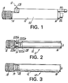
- Figure 1 is a side elevation view of a surgical shaver handpiece constructed in accordance with the principles of this invention.
- Figure 2 is a top view of Figure 1 showing the slide aspiration control valve in a fully closed, proximal-most position.
- Figure 3 is a top view of Figure 1 showing the slide aspiration control switch in a fully open, distal-most position.
- Figure 4 is an exploded partially cross-sectional view of Figure 1.
- Figure 5 is an assembled partially cross-sectional elevation view of Figure 1.
- Figure 6 is a cross-sectional view of Figure 4 taken along the lines 6-6.
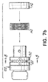
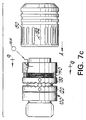
- Figures 7a, 7b and 7c are side elevation views of the collet subassembly shown in Figure 4 in various stages of assembly.
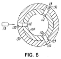
- Figure 8 is a cross-sectional view of Figure 7b taken along the line 8-8.
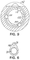
- Figure 9 is a cross-sectional view of Figure 7c taken along the line 9-9.
- Figure 10 is a cross-sectional view of Figure 4 taken along the line 10-10.
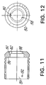
- Figure 11 is a cross-sectional elevation view of a portion of the collet subassembly of Figure 7c.
- Figure 12 is a right end view of Figure 11.
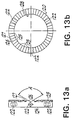
- Figures 13a and 13b are side and front elevation views, respectively, of a locking ring component shown in Figure 7a.
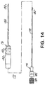
- Figure 14 is an exploded side elevation view, partially in cross-section, of a shaver blade for use with the handpiece of Figure 1.
- Handpiece 10 constructed in a modular fashion to facilitate its assembly and repair, comprises a body 12 having a distal end 14, a proximal end 16, a collet assembly 18, a motor/seal assembly 20 and a cable assembly 22.
- body 12 has two parallel, longitudinally extending throughbores: bore 24 is the main channel for receiving the motor/seal assembly 20 and collet assembly 18 and bore 26 is an aspirating channel which is provided with a slidable suction control valve 28 at the distal end 14 of body 12 and a tubing adapter 30 at the proximal end 16.
- An oblique aspiration communication channel 27 extends distally from bore 26 to bore 24.
- body 12 has a tear-drop shape which, in the preferred embodiment, is formed by extruding an extrudable material (aluminum, plastic, etc.) with throughbores 24 and 26.
- Oblique channel 27 and the annular grooves, threads and internal component receiving channels must be machined into body 12 after the extrusion step, but these are relatively minor manufacturing steps which are also employed in prior art non-extruded units. All known prior art handpieces are more expensive and time consuming to produce because they are machined entirely from a single bar of material.
- An additional advantage to extrusion is that, as will be understood below, it facilitates the use of a simplified slide aspiration control valve 28.
- collet assembly 18 which is shown in more detail in Figures 7a, b and c.
- collet assembly 18 serves to secure handpiece 10 to a shaver blade assembly.
- Collet inner body 100 is formed from an integral, hollow piece of material having a distal cylindrical portion 102, an intermediate cylindrical portion 104, a shoulder 106 and a proximal threaded portion 108.
- Cylindrical portion 102 is provided with three ball detents 110 equally spaced around the periphery of cylindrical portion 102 (only one ball detent is shown in Figure 7a).
- Cylindrical portion 104 is provided with three pin receiving apertures 112 (only one of which is shown) squally spaced around the periphery of cylindrical portion 104, the purpose of which will be explained below.
- Shoulder 106 is sized to smoothly abut collet body 100 against the distal opening 14 of handpiece body 12.
- Cylindrical threaded portion 108 is received in distal end 14 and secures the mounting of collet assembly 18 to handpiece body 12.
- Locking plate 120 is an annular ring having three equally spaced pin receiving apertures 122, a smooth proximally facing rear surface 124 and a toothed distally facing front surface 126.
- Locking ring 120 has an internal aperture 128 having a diameter sufficient to enable it to slide along intermediate cylindrical portion 104.
- An identical locking ring 130 is provided with three pin receiving apertures 132, a distally facing rear surface 134 and a proximally facing front surface 136.
- the central aperture of locking ring 130 is also sized to be received on intermediate portion 104 although locking ring 130 is fixed to portion 104 by pins 113 inserted through pin apertures 132 and into apertures 112, as best seen in Figure 8.
- a cylindrical pre-loading spring 140 sized to be received on cylindrical portion 102, is abutted against the distally facing rear surface of locking ring 130 and ball retaining ring 142 is then abutted against the distally facing side of spring 140.
- Balls 144 are then inserted into ball detents 110 as shown in Figures 7c and 9 and the entire assembly is held together by hollow, cylindrical outer collet body member 150 which is pinned via pin 153 to three equally spaced pin receiving apertures 152 to corresponding apertures 122 in locking ring 120, as best seen in Figure 10.
- Pre-loading spring 140 serves to cam balls 144 into the locked position and also to urge locking plate 120 against locking plate 130 (note they are spaced in Figure 7c for clarity).
- collet body 150 may be caused to move rearwardly (proximally) in the direction of arrow A by mere rotation.
- the mechanical advantage of the locking rings allows direct turning of the outer collet body without pulling it proximally or pushing it distally. It will be understood that turning the collet body 150 causes the facing front surfaces of the locking rings to disengage, thereby enabling relative rotation of the locking rings.
- Outer collet body 150 has a hollow interior 154 and an internal shoulder 156 which engages the distal side of ball retainer 142.
- a distal axially aligned aperture 158 is sized to receive a shaver blade assembly and is provided with a keyway 160 adapted to engage a corresponding key 192 on a shaver blade 172 best seen in Figure 14.
- shaver blade assembly 172 comprises an elongated inner blade 174 and an elongated outer blade 176.
- Inner blade 174 comprises an elongated tubular member 178 having a cutter 180 at its distal end and a hub 182 at its proximal end.
- Hub 182 includes a drive tang 184 to engage drive connection 185 of motor/seal assembly 20 (best seen in Figure 5) to drive the inner member.
- Outer blade 176 comprises an elongated tubular member 186 having a cutting window 188 at its distal end and a hub 190 at its proximal end.
- Hub 190 includes a key tang 192 which fits into the keyway of the outer collet body member.
- locking ring 120 has a central aperture 128 and a plurality of annularly arranged shallow teeth 125.
- the sides 126, 127 of adjacent teeth are separated by angle A which in the preferred embodiment is on the order of 119°.
- the shallow design of the teeth enables the locking rings to be easily rotated relative to one another without first having to push outer collet body longitudinally rearwardly to disengage the teeth.
- the teeth of one locking ring slide along the teeth of the other locking ring merely by manually rotating the outer collet body.
- the annular array of 24 teeth enables the collet to be adjustable throughout 360° in increments of 15°.
Landscapes
- Health & Medical Sciences (AREA)
- Life Sciences & Earth Sciences (AREA)
- Heart & Thoracic Surgery (AREA)
- Public Health (AREA)
- Veterinary Medicine (AREA)
- Biomedical Technology (AREA)
- Surgery (AREA)
- Engineering & Computer Science (AREA)
- Animal Behavior & Ethology (AREA)
- General Health & Medical Sciences (AREA)
- Orthopedic Medicine & Surgery (AREA)
- Vascular Medicine (AREA)
- Anesthesiology (AREA)
- Nuclear Medicine, Radiotherapy & Molecular Imaging (AREA)
- Hematology (AREA)
- Medical Informatics (AREA)
- Molecular Biology (AREA)
- Surgical Instruments (AREA)
- Saccharide Compounds (AREA)
- Agricultural Chemicals And Associated Chemicals (AREA)
- Sampling And Sample Adjustment (AREA)
- External Artificial Organs (AREA)
Claims (4)
- Chirurgisches Gerät (10) zum Antreiben eines länglichen chirurgischen Werkzeugs (172), wobei das Gerät aufweist:dadurch gekennzeichnet, daß die Ringeinrichtung eine Arretiervorrichtung aufweist, um den Ring in einer gewählten Position zu halten, wobei die Arretiervorrichtung manuell drehbar ist, ohne zuerst manuell in Längsrichtung gezwungen zu werden, wobei die Arretiervorrichtung ferner aufweist:ein Gehäuse (12);eine Antriebseinrichtung (20) innerhalb des Gehäuses (12);eine lösbare Ringeinrichtung (18), um das chirurgische Werkzeug (172) aufzunehmen und es in Längsrichtung fixiert relativ zur Antriebseinrichtung (20) zu halten;eine erste Verschlußplatte (120) mit einer ersten Verschlußfläche (125), die in eine distale Richtung zeigt;eine zweite Verschlußplatte (130) mit einer zweiten Verschlußfläche (136), die in eine proximale Richtung zeigt, wobei die erste und zweite Verschlußfläche (125,136) angepaßt sind, um ineinander zu greifen, um eine relative Drehung zwischen der ersten und zweiten Verschlußplatte (120,136) zu verhindern;ein hohles zylindrisches Ringglied (150), das fest an der ersten Verschlußplatte (120) angebracht ist; undeine zwischen dem Ringglied (150) und der zweiten Verschlußplatte (130) angeordnete Federeinrichtung (140), um die erste und zweite Verschlußfläche (125,136) selektiv im Eingriff zu halten.
- Chirurgisches Gerät nach Anspruch 1, wobei die erste und zweite Verschlußfläche (125,136) ringförmig sind und mehrere ringförmig angeordnete Zähne (125) aufweisen, die mehrere durch mehrere Einkerbungen beabstandete Spitzen aufweisen, wobei die Zähne (125) der ersten Verschlußfläche (125) angepaßt sind, um in die Zähne (125) der zweiten Verschlußfläche (136) zu greifen.
- Chirurgisches Gerät nach Anspruch 1, wobei benachbarte Zähne (125) Seiten haben, die in einem Winkel von ungefähr 120° zusammenlaufen.
- Kombination aus einem länglichen chirurgischen Werkzeug (172) mit einem drehbaren inneren Glied (174), das drehbar innerhalb eines äußeren Glieds (176) angeordnet ist, wobei das äußere Glied ein Schneidfenster (188) hat, das zumindest teilweise in eine Richtung quer zur Achse liegt, und aus einem chirurgischen Gerät (10) mit:dadurch gekennzeichnet, daß die Einrichtung zur Ermöglichung einer Drehung eine Arretiervorrichtung aufweist, um den Ring in einer gewählten Position zu halten, wobei die Arretiervorrichtung manuell drehbar ist, ohne zuerst manuell in Längsrichtung gezwungen zu werden, wobei die Arretiervorrichtung ferner aufweist:einem Gehäuse (12);einer Antriebseinrichtung (20) innerhalb des Gehäuses zum Antreiben des inneren Glieds des Werkzeugs;einer lösbaren Ringeinrichtung (18), um das chirurgische Werkzeug (172) aufzunehmen und es in Längsrichtung fixiert relativ zur Antriebseinrichtung (20) zu halten, wobei die Ringeinrichtung (18) das äußere Glied (176) des Werkzeugs (172) in einer vorgegebenen Winkelorientierung relativ zur Achse des Gehäuses (12) aufnimmt; undeiner Einrichtung zur Ermöglichung einer Drehung der Ringeinrichtung (18) zum Ändern der vorgegebenen Winkelorientierung,eine erste Verschlußplatte (120) mit einer ersten Verschlußfläche (125), die in eine distale Richtung zeigt;eine zweite Verschlußplatte (130) mit einer zweiten Verschlußfläche (136), die in eine proximale Richtung zeigt, wobei die erste und zweite Verschlußfläche (125,136) ineinandergreifen, um eine relative Drehung zwischen der ersten und zweiten Verschlußplatte (120,130) zu verhindern;ein hohles zylindrisches Ringglied (150), das fest an der ersten Verschlußplatte (120) angebracht ist und eine Keilnuteinrichtung (160) zur Fixierung der Position des äußeren Glieds (176) hat; undeine zwischen dem Ringglied (150) und der zweiten Verschlußplatte (130) liegende Federeinrichtung (140), um die erste und zweite Verschlußfläche (125,136) selektiv im Eingriff zu halten.
Priority Applications (1)
| Application Number | Priority Date | Filing Date | Title |
|---|---|---|---|
| EP01122090A EP1166722B1 (de) | 1994-09-09 | 1995-09-08 | Maschinenangetriebenes chirugisches Gerät für Arthroskopie |
Applications Claiming Priority (2)
| Application Number | Priority Date | Filing Date | Title |
|---|---|---|---|
| US303910 | 1994-09-09 | ||
| US08/303,910 US5492527A (en) | 1994-09-09 | 1994-09-09 | Arthroscopic shaver with rotatable collet and slide aspiration control valve |
Related Child Applications (1)
| Application Number | Title | Priority Date | Filing Date |
|---|---|---|---|
| EP01122090A Division EP1166722B1 (de) | 1994-09-09 | 1995-09-08 | Maschinenangetriebenes chirugisches Gerät für Arthroskopie |
Publications (3)
| Publication Number | Publication Date |
|---|---|
| EP0700663A2 EP0700663A2 (de) | 1996-03-13 |
| EP0700663A3 EP0700663A3 (de) | 1996-05-01 |
| EP0700663B1 true EP0700663B1 (de) | 2002-03-27 |
Family
ID=23174232
Family Applications (2)
| Application Number | Title | Priority Date | Filing Date |
|---|---|---|---|
| EP95202448A Expired - Lifetime EP0700663B1 (de) | 1994-09-09 | 1995-09-08 | Maschinenangetriebenes chirugisches Gerät für Arthroskopie mit Absaugrohr |
| EP01122090A Expired - Lifetime EP1166722B1 (de) | 1994-09-09 | 1995-09-08 | Maschinenangetriebenes chirugisches Gerät für Arthroskopie |
Family Applications After (1)
| Application Number | Title | Priority Date | Filing Date |
|---|---|---|---|
| EP01122090A Expired - Lifetime EP1166722B1 (de) | 1994-09-09 | 1995-09-08 | Maschinenangetriebenes chirugisches Gerät für Arthroskopie |
Country Status (7)
| Country | Link |
|---|---|
| US (2) | US5492527A (de) |
| EP (2) | EP0700663B1 (de) |
| JP (1) | JPH0898843A (de) |
| AT (2) | ATE253869T1 (de) |
| AU (1) | AU689613B2 (de) |
| CA (1) | CA2157805A1 (de) |
| ES (1) | ES2171495T3 (de) |
Families Citing this family (97)
| Publication number | Priority date | Publication date | Assignee | Title |
|---|---|---|---|---|
| US5871493A (en) * | 1995-10-31 | 1999-02-16 | Smith & Nephew Endoscopy Inc. | Surgical instrument handpiece and system |
| US5941876A (en) * | 1996-03-11 | 1999-08-24 | Medical Scientific, Inc. | Electrosurgical rotating cutting device |
| US5925040A (en) * | 1997-06-18 | 1999-07-20 | Medical Scientific, Inc. | Electrosurgical instrument having a segmented roller electrode |
| EP1076499B1 (de) * | 1998-05-06 | 2004-07-21 | Hill-Rom Services, Inc. | Matratze/kissenaufbau |
| US6494892B1 (en) | 1998-10-20 | 2002-12-17 | Suros Surgical Systems, Inc. | Disposable hub for a surgical cutting instrument |
| DE19859217B4 (de) * | 1998-12-21 | 2004-01-29 | Richard Wolf Gmbh | Elektromotorischer Antrieb für ein chirurgisches Werkzeug |
| US6312441B1 (en) * | 1999-03-04 | 2001-11-06 | Stryker Corporation | Powered handpiece for performing endoscopic surgical procedures |
| US6193715B1 (en) | 1999-03-19 | 2001-02-27 | Medical Scientific, Inc. | Device for converting a mechanical cutting device to an electrosurgical cutting device |
| US6689146B1 (en) * | 1999-04-29 | 2004-02-10 | Stryker Corporation | Powered surgical handpiece with integrated irrigator and suction application |
| US6436067B1 (en) | 1999-12-03 | 2002-08-20 | Stryker Corporation | Powered surgical handpiece with suction conduit including a stepped valve to regulate flow through the suction conduit |
| US6517560B1 (en) | 2000-11-27 | 2003-02-11 | Duke University | Hand-held surgical instruments employing magnetic couplings for simultaneous rotary and longitudinal oscillations of distal workpieces |
| US6478681B1 (en) | 2000-11-27 | 2002-11-12 | Duke University | Magnetic couplings for imparting simultaneous rotary and longitudinal oscillations |
| US8599250B2 (en) * | 2002-03-12 | 2013-12-03 | Karl Storz Imaging, Inc. | Wireless camera coupling |
| US8723936B2 (en) | 2002-03-12 | 2014-05-13 | Karl Storz Imaging, Inc. | Wireless camera coupling with rotatable coupling |
| US9510740B2 (en) * | 2002-03-12 | 2016-12-06 | Karl Storz Endovision, Inc. | Auto recognition of a shaver blade for medical use |
| US8194122B2 (en) * | 2002-03-12 | 2012-06-05 | Karl Storz Imaging, Inc. | Universal scope reader |
| USD478986S1 (en) | 2002-03-22 | 2003-08-26 | Gyrus Ent L.L.C. | Surgical tool |
| USD484595S1 (en) | 2002-03-22 | 2003-12-30 | Gyrus Ent L.L.C. | Surgical tool blade holder |
| US7247161B2 (en) * | 2002-03-22 | 2007-07-24 | Gyrus Ent L.L.C. | Powered surgical apparatus, method of manufacturing powered surgical apparatus, and method of using powered surgical apparatus |
| USD484596S1 (en) | 2002-03-22 | 2003-12-30 | Gyrus Ent L.L.C. | Surgical tool blade holder |
| USD478665S1 (en) | 2002-03-22 | 2003-08-19 | Gyrus Ent L.L.C. | Disposable trigger |
| USD484243S1 (en) | 2002-03-22 | 2003-12-23 | Gyrus Ent L.L.C. | Surgical tool blade holder |
| USD484977S1 (en) | 2002-03-22 | 2004-01-06 | Gyrus Ent L.L.C. | Surgical tool blade holder |
| US6958071B2 (en) * | 2002-07-13 | 2005-10-25 | Stryker Corporation | Surgical tool system |
| US20040147909A1 (en) * | 2002-12-20 | 2004-07-29 | Gyrus Ent L.L.C. | Surgical instrument |
| EP1452192B1 (de) * | 2003-02-27 | 2016-06-29 | Smiths Group plc | Absaugkatheteranordnung und ventile |
| US8277474B2 (en) | 2004-05-26 | 2012-10-02 | Medtronic, Inc. | Surgical cutting instrument |
| WO2006102124A2 (en) * | 2005-03-17 | 2006-09-28 | Stryker Corporation | Surgical tool arrangement |
| JP4905647B2 (ja) * | 2006-02-14 | 2012-03-28 | 朝日インテック株式会社 | 医療用具 |
| US10653497B2 (en) | 2006-02-16 | 2020-05-19 | Globus Medical, Inc. | Surgical tool systems and methods |
| US10357184B2 (en) * | 2012-06-21 | 2019-07-23 | Globus Medical, Inc. | Surgical tool systems and method |
| US10893912B2 (en) | 2006-02-16 | 2021-01-19 | Globus Medical Inc. | Surgical tool systems and methods |
| DE102007006276A1 (de) * | 2007-01-31 | 2008-08-07 | Karl Storz Gmbh & Co. Kg | Medizinisches Instrument zum Schneiden von Gewebe |
| JP4939971B2 (ja) * | 2007-02-20 | 2012-05-30 | 株式会社東芝 | 不揮発性半導体メモリ |
| US8906053B2 (en) * | 2007-11-12 | 2014-12-09 | Medtronic Xomed, Inc. | Systems and methods for surgical removal of brain tumors |
| GB2462828B (en) * | 2008-08-19 | 2012-12-05 | Soutter Medical Ltd De | A medical device |
| US8821486B2 (en) | 2009-11-13 | 2014-09-02 | Hermes Innovations, LLC | Tissue ablation systems and methods |
| US9662163B2 (en) | 2008-10-21 | 2017-05-30 | Hermes Innovations Llc | Endometrial ablation devices and systems |
| US8540708B2 (en) | 2008-10-21 | 2013-09-24 | Hermes Innovations Llc | Endometrial ablation method |
| US8070765B2 (en) * | 2009-01-28 | 2011-12-06 | Medtronic Xomed, Inc. | Systems and methods for surgical removal of brain tumors |
| AU2010218473B2 (en) | 2009-02-26 | 2014-03-06 | Stryker Corporation | Surgical tool arrangement having a handpiece usable with multiple surgical tools |
| CN101507649B (zh) * | 2009-03-23 | 2011-04-13 | 徐生源 | 用于切骨手术的电动切除器 |
| US8308043B2 (en) * | 2009-05-19 | 2012-11-13 | Covidien Lp | Recognition of interchangeable component of a device |
| US8435259B2 (en) * | 2009-05-19 | 2013-05-07 | Stryker Corporation | Surgical tool arrangement and surgical cutting accessory for use therewith with the tool arrangement including a toothed cutting edge and a generally straight cutting edge |
| CH701320B1 (it) * | 2009-06-16 | 2013-10-15 | Frii S A | Dispositivo per trattamenti di resezione/rimozione endoscopica dei tessuti. |
| CH701321B1 (it) | 2009-06-16 | 2013-10-15 | Frii S A | Dispositivo per trattamenti di resezione/rimozione endoscopica dei tessuti. |
| IN2012DN01917A (de) | 2009-09-08 | 2015-07-24 | Salient Surgical Tech Inc | |
| US11896282B2 (en) | 2009-11-13 | 2024-02-13 | Hermes Innovations Llc | Tissue ablation systems and method |
| US8409235B2 (en) | 2010-04-30 | 2013-04-02 | Medtronic Xomed, Inc. | Rotary cutting tool with improved cutting and reduced clogging on soft tissue and thin bone |
| DE102011001265A1 (de) * | 2011-03-14 | 2012-09-20 | Aesculap Ag | Einstellbarer Absaug-Shaver |
| US9668762B2 (en) * | 2011-03-30 | 2017-06-06 | Smith & Nephew, Inc. | Medical device |
| CH705201B1 (it) * | 2011-06-22 | 2015-02-27 | Frii S A | Dispositivo per trattamenti di resezione/rimozione endoscopica dei tessuti. |
| US8753344B2 (en) * | 2011-09-23 | 2014-06-17 | Smith & Nephew, Inc. | Dynamic orthoscopic sensing |
| US9226792B2 (en) | 2012-06-12 | 2016-01-05 | Medtronic Advanced Energy Llc | Debridement device and method |
| US11395706B2 (en) | 2012-06-21 | 2022-07-26 | Globus Medical Inc. | Surgical robot platform |
| US10136954B2 (en) | 2012-06-21 | 2018-11-27 | Globus Medical, Inc. | Surgical tool systems and method |
| JP2015528713A (ja) | 2012-06-21 | 2015-10-01 | グローバス メディカル インコーポレイティッド | 手術ロボットプラットフォーム |
| US12310683B2 (en) | 2012-06-21 | 2025-05-27 | Globus Medical, Inc. | Surgical tool systems and method |
| US20150032164A1 (en) | 2012-06-21 | 2015-01-29 | Globus Medical, Inc. | Methods for Performing Invasive Medical Procedures Using a Surgical Robot |
| US11607149B2 (en) * | 2012-06-21 | 2023-03-21 | Globus Medical Inc. | Surgical tool systems and method |
| US10350013B2 (en) | 2012-06-21 | 2019-07-16 | Globus Medical, Inc. | Surgical tool systems and methods |
| JP5696259B2 (ja) | 2012-06-29 | 2015-04-08 | ジャイラス・エーシーエムアイ・インコーポレーテッド | 手術器具のためのブレード保持機構 |
| USD691718S1 (en) | 2012-08-23 | 2013-10-15 | Gyrus Acmi, Inc. | Microdebrider |
| US8956355B2 (en) | 2012-11-30 | 2015-02-17 | Gyrus Acmi, Inc. | Integrated blade assembly and identification circuit |
| CH707372B1 (it) | 2012-12-19 | 2016-07-29 | Frii Sa | Dispositivo per trattamenti di resezione/rimozione endoscopica dei tessuti. |
| CN107252340B (zh) | 2013-02-26 | 2020-04-21 | 捷锐士阿希迈公司(以奥林巴斯美国外科技术名义) | 具有闭锁机构的可更换式清创器刀片模块 |
| US9358036B2 (en) | 2013-03-12 | 2016-06-07 | Gyrus Acmi, Inc. | Blade positioning device |
| US9839441B2 (en) | 2013-03-14 | 2017-12-12 | Stryker Corporation | Surgical tool arrangement and surgical cutting accessory for use therewith |
| US9636131B2 (en) | 2013-03-15 | 2017-05-02 | Stryker Corporation | Surgical tool arrangement and surgical cutting accessory for use therewith |
| US9649125B2 (en) | 2013-10-15 | 2017-05-16 | Hermes Innovations Llc | Laparoscopic device |
| JP7107635B2 (ja) * | 2013-10-24 | 2022-07-27 | グローバス メディカル インコーポレイティッド | 外科用ツールシステム及び方法 |
| US10314647B2 (en) | 2013-12-23 | 2019-06-11 | Medtronic Advanced Energy Llc | Electrosurgical cutting instrument |
| US10813686B2 (en) | 2014-02-26 | 2020-10-27 | Medtronic Advanced Energy Llc | Electrosurgical cutting instrument |
| US9387050B2 (en) | 2014-09-15 | 2016-07-12 | Gyrus Acmi Inc. | Surgical system having detachable component and state detection circuit for detection of state of attachment of detachable component |
| US10470786B2 (en) | 2014-10-16 | 2019-11-12 | Stryker Corporation | Surgical tool arrangement and surgical cutting accessory for use therewith |
| US10166036B2 (en) | 2014-10-16 | 2019-01-01 | Gyrus Acmi, Inc. | Variable suction control |
| US10376302B2 (en) | 2015-02-18 | 2019-08-13 | Medtronic Xomed, Inc. | Rotating electrical connector for RF energy enabled tissue debridement device |
| US10188456B2 (en) | 2015-02-18 | 2019-01-29 | Medtronic Xomed, Inc. | Electrode assembly for RF energy enabled tissue debridement device |
| WO2016134156A1 (en) | 2015-02-18 | 2016-08-25 | Medtronic Xomed, Inc. | Rf energy enabled tissue debridement device |
| US9820825B2 (en) | 2015-02-20 | 2017-11-21 | Gyrus Acmi Inc. | Surgical system having plurality of detachably attachable components and circuit for detecting target states of detachably attachable components and performing control based on detected target states, and method for providing surgical system |
| JP6814746B2 (ja) | 2015-04-29 | 2021-01-20 | シーラス テクノロジーズ リミテッド | 医療用アブレーションデバイスおよび使用方法 |
| US10716612B2 (en) | 2015-12-18 | 2020-07-21 | Medtronic Advanced Energy Llc | Electrosurgical device with multiple monopolar electrode assembly |
| US10052149B2 (en) | 2016-01-20 | 2018-08-21 | RELIGN Corporation | Arthroscopic devices and methods |
| AU2017236701B2 (en) | 2016-03-24 | 2022-04-07 | Stryker European Operations Holdings Llc | Surgical instrument having cutting assembly with grip |
| EP3241518B1 (de) | 2016-04-11 | 2024-10-23 | Globus Medical, Inc | Systeme für chirurgische werkzeuge |
| WO2017185097A1 (en) * | 2016-04-22 | 2017-10-26 | RELIGN Corporation | Arthroscopic devices and methods |
| US20180000534A1 (en) | 2016-07-01 | 2018-01-04 | RELIGN Corporation | Arthroscopic devices and methods |
| CN110996816B (zh) | 2017-07-25 | 2023-06-30 | 史赛克欧洲运营有限责任公司 | 用于与外科手术系统一起使用的冲洗套管 |
| EP3661435B1 (de) | 2017-08-02 | 2022-12-21 | Stryker Corporation | Chirurgische instrumentensysteme |
| US12023082B2 (en) | 2017-10-06 | 2024-07-02 | Medtronic Advanced Energy Llc | Hemostatic thermal sealer |
| KR200487712Y1 (ko) * | 2018-06-19 | 2018-10-24 | 김주원 | 수술용 쉐이버 |
| EP3813684B1 (de) * | 2018-06-27 | 2024-12-04 | Boston Scientific Scimed, Inc. | Endoskopbefestigungsmechanismus zur verwendung mit einer verschlussvorrichtung auf nahtbasis |
| EP4316394B1 (de) | 2019-01-15 | 2026-02-04 | Stryker European Operations Limited | Chirurgische ultraschall-irrigationshülse und zugehörige anordnungen |
| US11554214B2 (en) | 2019-06-26 | 2023-01-17 | Meditrina, Inc. | Fluid management system |
| US11253371B2 (en) | 2019-12-27 | 2022-02-22 | Henry F. Fabian, JR. | Vertebral body shaver assembly |
| US11957373B2 (en) | 2020-05-12 | 2024-04-16 | Smith & Nephew, Inc. | Systems and methods of determining orientation of cutting windows of a mechanical resection instrument |
| USD977095S1 (en) * | 2020-05-29 | 2023-01-31 | Medos International Sarl | Handpiece |
Family Cites Families (22)
| Publication number | Priority date | Publication date | Assignee | Title |
|---|---|---|---|---|
| US3223088A (en) * | 1963-04-08 | 1965-12-14 | S B Power Surgical Tools Compa | Bone cutting apparatus |
| DE1808853A1 (de) * | 1968-11-14 | 1970-06-04 | Augsburg Nuernberg Ag Zweignie | Vorrichtung zum Abtasten kodierter Werkzeuge fuer numerisch gesteuerte Werkzeugmaschinen |
| US3618611A (en) * | 1969-03-05 | 1971-11-09 | Julius C Urban | Vacuum rotary dissector |
| JPS517000B1 (de) * | 1970-01-05 | 1976-03-03 | ||
| US3835858A (en) * | 1972-09-05 | 1974-09-17 | Weck & Co Inc Edward | Surgical air drill |
| US3847154A (en) * | 1972-09-22 | 1974-11-12 | Weck & Co Edward | Surgical drill with detachable hand-piece |
| US4014342A (en) * | 1975-04-11 | 1977-03-29 | Concept, Inc. | Vitreous cutter |
| US4071029A (en) * | 1976-05-21 | 1978-01-31 | Stryker Corporation | Angle handpiece |
| AU2741577A (en) * | 1976-08-09 | 1979-02-01 | American Safety Equip | Automatic chuck for drill |
| USRE34556E (en) * | 1985-01-23 | 1994-03-01 | Smith & Nephew Dyonics Inc. | Surgical system for powered instruments |
| US4674502A (en) * | 1985-09-27 | 1987-06-23 | Coopervision, Inc. | Intraocular surgical instrument |
| US5217478A (en) * | 1987-02-18 | 1993-06-08 | Linvatec Corporation | Arthroscopic surgical instrument drive system |
| US4900252A (en) * | 1987-07-24 | 1990-02-13 | Siemens Aktiengesellschaft | Recognition system for tools insertable into dental treatment instruments |
| DE3906301A1 (de) * | 1988-04-28 | 1989-12-14 | Olympus Optical Co | Chirurgisches resektionsinstrument |
| US5112299A (en) * | 1989-10-25 | 1992-05-12 | Hall Surgical Division Of Zimmer, Inc. | Arthroscopic surgical apparatus and method |
| US5133729A (en) * | 1990-08-17 | 1992-07-28 | Smith & Nephew Dyonics Inc. | Motor driven hand piece for a surgical tool |
| DE4026452C2 (de) * | 1990-08-21 | 1993-12-02 | Schott Glaswerke | Vorrichtung zur Erkennung und Unterscheidung von unter eine Steckverbindung an einen Laser anschließbaren medizinischen Einwegapplikatoren |
| US5352235A (en) * | 1992-03-16 | 1994-10-04 | Tibor Koros | Laparoscopic grasper and cutter |
| US5368606A (en) * | 1992-07-02 | 1994-11-29 | Marlow Surgical Technologies, Inc. | Endoscopic instrument system |
| US5352234A (en) * | 1992-10-08 | 1994-10-04 | Midas Rex Pneumatic Tools, Inc. | Surgical instrument with angular swivel |
| US5286253A (en) * | 1992-10-09 | 1994-02-15 | Linvatec Corporation | Angled rotating surgical instrument |
| US5376078B1 (en) * | 1992-12-10 | 1997-06-24 | Linvatec Corp | Rotatable surgical cutting instrument with positionally adjustable window |
-
1994
- 1994-09-09 US US08/303,910 patent/US5492527A/en not_active Expired - Lifetime
-
1995
- 1995-08-24 AU AU30245/95A patent/AU689613B2/en not_active Ceased
- 1995-09-08 AT AT01122090T patent/ATE253869T1/de not_active IP Right Cessation
- 1995-09-08 CA CA002157805A patent/CA2157805A1/en not_active Abandoned
- 1995-09-08 ES ES95202448T patent/ES2171495T3/es not_active Expired - Lifetime
- 1995-09-08 EP EP95202448A patent/EP0700663B1/de not_active Expired - Lifetime
- 1995-09-08 EP EP01122090A patent/EP1166722B1/de not_active Expired - Lifetime
- 1995-09-08 AT AT95202448T patent/ATE214896T1/de not_active IP Right Cessation
- 1995-09-11 JP JP7232581A patent/JPH0898843A/ja active Pending
- 1995-10-12 US US08/542,204 patent/US5592727A/en not_active Expired - Lifetime
Also Published As
| Publication number | Publication date |
|---|---|
| EP0700663A3 (de) | 1996-05-01 |
| US5492527A (en) | 1996-02-20 |
| AU3024595A (en) | 1996-03-21 |
| AU689613B2 (en) | 1998-04-02 |
| JPH0898843A (ja) | 1996-04-16 |
| EP1166722A1 (de) | 2002-01-02 |
| US5592727A (en) | 1997-01-14 |
| ATE214896T1 (de) | 2002-04-15 |
| EP0700663A2 (de) | 1996-03-13 |
| CA2157805A1 (en) | 1996-03-10 |
| EP1166722B1 (de) | 2003-11-12 |
| ES2171495T3 (es) | 2002-09-16 |
| ATE253869T1 (de) | 2003-11-15 |
Similar Documents
| Publication | Publication Date | Title |
|---|---|---|
| EP1166722B1 (de) | Maschinenangetriebenes chirugisches Gerät für Arthroskopie | |
| US11219452B2 (en) | Surgical cutting and stapling device | |
| US5376078A (en) | Rotatable surgical cutting instrument with positionally adjustable window | |
| EP0647433B1 (de) | Endoskopisches chirurgisches Instrument mit drehbarem inneren Schaft | |
| US6958071B2 (en) | Surgical tool system | |
| US6068641A (en) | Irrigated burr | |
| EP1622521B1 (de) | Operationsinstrument mit abnehmbarem schaft und verfahren | |
| US9955993B2 (en) | Surgical tool system with quick release coupling assembly | |
| US5709698A (en) | Irrigating/aspirating shaver blade assembly | |
| US5464300A (en) | Medical instrument and coupling apparatus for same | |
| US20030050603A1 (en) | Cannula that provides bi-directional fluid flow that is regulated by a single valve | |
| US8845668B2 (en) | Arthroscopic shaver handpiece with modular attachments | |
| US20040147909A1 (en) | Surgical instrument | |
| EP4464272B1 (de) | Schneidanordnung und antriebsanordnung für ein chirurgisches instrument | |
| US6436067B1 (en) | Powered surgical handpiece with suction conduit including a stepped valve to regulate flow through the suction conduit | |
| CA3018655A1 (en) | Surgical instrument having cutting assembly with grip | |
| US20240008896A1 (en) | Expandable surgical access port | |
| US12364500B2 (en) | Tissue resecting instrument |
Legal Events
| Date | Code | Title | Description |
|---|---|---|---|
| PUAI | Public reference made under article 153(3) epc to a published international application that has entered the european phase |
Free format text: ORIGINAL CODE: 0009012 |
|
| AK | Designated contracting states |
Kind code of ref document: A2 Designated state(s): AT BE CH DK ES FR GB GR IE IT LI LU NL SE |
|
| PUAL | Search report despatched |
Free format text: ORIGINAL CODE: 0009013 |
|
| AK | Designated contracting states |
Kind code of ref document: A3 Designated state(s): AT BE CH DK ES FR GB GR IE IT LI LU NL SE |
|
| 17P | Request for examination filed |
Effective date: 19961104 |
|
| RAP1 | Party data changed (applicant data changed or rights of an application transferred) |
Owner name: LINVATEC CORPORATION |
|
| 17Q | First examination report despatched |
Effective date: 19990607 |
|
| GRAG | Despatch of communication of intention to grant |
Free format text: ORIGINAL CODE: EPIDOS AGRA |
|
| GRAG | Despatch of communication of intention to grant |
Free format text: ORIGINAL CODE: EPIDOS AGRA |
|
| GRAH | Despatch of communication of intention to grant a patent |
Free format text: ORIGINAL CODE: EPIDOS IGRA |
|
| GRAH | Despatch of communication of intention to grant a patent |
Free format text: ORIGINAL CODE: EPIDOS IGRA |
|
| REG | Reference to a national code |
Ref country code: GB Ref legal event code: IF02 |
|
| GRAA | (expected) grant |
Free format text: ORIGINAL CODE: 0009210 |
|
| AK | Designated contracting states |
Kind code of ref document: B1 Designated state(s): AT BE CH DK ES FR GB GR IE IT LI LU NL SE |
|
| PG25 | Lapsed in a contracting state [announced via postgrant information from national office to epo] |
Ref country code: NL Free format text: LAPSE BECAUSE OF FAILURE TO SUBMIT A TRANSLATION OF THE DESCRIPTION OR TO PAY THE FEE WITHIN THE PRESCRIBED TIME-LIMIT Effective date: 20020327 Ref country code: LI Free format text: LAPSE BECAUSE OF FAILURE TO SUBMIT A TRANSLATION OF THE DESCRIPTION OR TO PAY THE FEE WITHIN THE PRESCRIBED TIME-LIMIT Effective date: 20020327 Ref country code: GR Free format text: LAPSE BECAUSE OF FAILURE TO SUBMIT A TRANSLATION OF THE DESCRIPTION OR TO PAY THE FEE WITHIN THE PRESCRIBED TIME-LIMIT Effective date: 20020327 Ref country code: CH Free format text: LAPSE BECAUSE OF FAILURE TO SUBMIT A TRANSLATION OF THE DESCRIPTION OR TO PAY THE FEE WITHIN THE PRESCRIBED TIME-LIMIT Effective date: 20020327 Ref country code: AT Free format text: LAPSE BECAUSE OF FAILURE TO SUBMIT A TRANSLATION OF THE DESCRIPTION OR TO PAY THE FEE WITHIN THE PRESCRIBED TIME-LIMIT Effective date: 20020327 |
|
| REF | Corresponds to: |
Ref document number: 214896 Country of ref document: AT Date of ref document: 20020415 Kind code of ref document: T |
|
| REG | Reference to a national code |
Ref country code: CH Ref legal event code: EP |
|
| REG | Reference to a national code |
Ref country code: IE Ref legal event code: FG4D |
|
| PG25 | Lapsed in a contracting state [announced via postgrant information from national office to epo] |
Ref country code: SE Free format text: LAPSE BECAUSE OF FAILURE TO SUBMIT A TRANSLATION OF THE DESCRIPTION OR TO PAY THE FEE WITHIN THE PRESCRIBED TIME-LIMIT Effective date: 20020627 Ref country code: DK Free format text: LAPSE BECAUSE OF FAILURE TO SUBMIT A TRANSLATION OF THE DESCRIPTION OR TO PAY THE FEE WITHIN THE PRESCRIBED TIME-LIMIT Effective date: 20020627 |
|
| NLV1 | Nl: lapsed or annulled due to failure to fulfill the requirements of art. 29p and 29m of the patents act | ||
| PG25 | Lapsed in a contracting state [announced via postgrant information from national office to epo] |
Ref country code: LU Free format text: LAPSE BECAUSE OF NON-PAYMENT OF DUE FEES Effective date: 20020908 |
|
| PG25 | Lapsed in a contracting state [announced via postgrant information from national office to epo] |
Ref country code: IE Free format text: LAPSE BECAUSE OF NON-PAYMENT OF DUE FEES Effective date: 20020909 |
|
| REG | Reference to a national code |
Ref country code: ES Ref legal event code: FG2A Ref document number: 2171495 Country of ref document: ES Kind code of ref document: T3 |
|
| REG | Reference to a national code |
Ref country code: CH Ref legal event code: PL |
|
| PLBE | No opposition filed within time limit |
Free format text: ORIGINAL CODE: 0009261 |
|
| STAA | Information on the status of an ep patent application or granted ep patent |
Free format text: STATUS: NO OPPOSITION FILED WITHIN TIME LIMIT |
|
| 26N | No opposition filed |
Effective date: 20021230 |
|
| REG | Reference to a national code |
Ref country code: IE Ref legal event code: MM4A |
|
| PGFP | Annual fee paid to national office [announced via postgrant information from national office to epo] |
Ref country code: ES Payment date: 20050916 Year of fee payment: 11 |
|
| PGFP | Annual fee paid to national office [announced via postgrant information from national office to epo] |
Ref country code: GB Payment date: 20060804 Year of fee payment: 12 |
|
| PGFP | Annual fee paid to national office [announced via postgrant information from national office to epo] |
Ref country code: FR Payment date: 20060906 Year of fee payment: 12 |
|
| PGFP | Annual fee paid to national office [announced via postgrant information from national office to epo] |
Ref country code: IT Payment date: 20060930 Year of fee payment: 12 |
|
| PGFP | Annual fee paid to national office [announced via postgrant information from national office to epo] |
Ref country code: BE Payment date: 20061005 Year of fee payment: 12 |
|
| BERE | Be: lapsed |
Owner name: *LINVATEC CORP. Effective date: 20070930 |
|
| GBPC | Gb: european patent ceased through non-payment of renewal fee |
Effective date: 20070908 |
|
| PG25 | Lapsed in a contracting state [announced via postgrant information from national office to epo] |
Ref country code: BE Free format text: LAPSE BECAUSE OF NON-PAYMENT OF DUE FEES Effective date: 20070930 |
|
| REG | Reference to a national code |
Ref country code: FR Ref legal event code: ST Effective date: 20080531 |
|
| PG25 | Lapsed in a contracting state [announced via postgrant information from national office to epo] |
Ref country code: FR Free format text: LAPSE BECAUSE OF NON-PAYMENT OF DUE FEES Effective date: 20071001 |
|
| PG25 | Lapsed in a contracting state [announced via postgrant information from national office to epo] |
Ref country code: GB Free format text: LAPSE BECAUSE OF NON-PAYMENT OF DUE FEES Effective date: 20070908 |
|
| REG | Reference to a national code |
Ref country code: ES Ref legal event code: FD2A Effective date: 20070910 |
|
| PG25 | Lapsed in a contracting state [announced via postgrant information from national office to epo] |
Ref country code: ES Free format text: LAPSE BECAUSE OF NON-PAYMENT OF DUE FEES Effective date: 20070910 |
|
| PG25 | Lapsed in a contracting state [announced via postgrant information from national office to epo] |
Ref country code: IT Free format text: LAPSE BECAUSE OF NON-PAYMENT OF DUE FEES Effective date: 20070908 |