EP0701037A1 - Serrure pour portes de prison - Google Patents
Serrure pour portes de prison Download PDFInfo
- Publication number
- EP0701037A1 EP0701037A1 EP95113819A EP95113819A EP0701037A1 EP 0701037 A1 EP0701037 A1 EP 0701037A1 EP 95113819 A EP95113819 A EP 95113819A EP 95113819 A EP95113819 A EP 95113819A EP 0701037 A1 EP0701037 A1 EP 0701037A1
- Authority
- EP
- European Patent Office
- Prior art keywords
- bolt
- key
- locking
- lock
- lever
- Prior art date
- Legal status (The legal status is an assumption and is not a legal conclusion. Google has not performed a legal analysis and makes no representation as to the accuracy of the status listed.)
- Granted
Links
- 230000008859 change Effects 0.000 claims description 40
- 230000008719 thickening Effects 0.000 claims description 3
- 230000007717 exclusion Effects 0.000 claims description 2
- 230000007246 mechanism Effects 0.000 abstract description 3
- 230000008878 coupling Effects 0.000 description 4
- 238000010168 coupling process Methods 0.000 description 4
- 238000005859 coupling reaction Methods 0.000 description 4
- 230000008901 benefit Effects 0.000 description 1
- 230000006735 deficit Effects 0.000 description 1
- 210000003746 feather Anatomy 0.000 description 1
- 210000003608 fece Anatomy 0.000 description 1
Images



Classifications
-
- E—FIXED CONSTRUCTIONS
- E05—LOCKS; KEYS; WINDOW OR DOOR FITTINGS; SAFES
- E05B—LOCKS; ACCESSORIES THEREFOR; HANDCUFFS
- E05B59/00—Locks with latches separate from the lock-bolts or with a plurality of latches or lock-bolts
-
- E—FIXED CONSTRUCTIONS
- E05—LOCKS; KEYS; WINDOW OR DOOR FITTINGS; SAFES
- E05B—LOCKS; ACCESSORIES THEREFOR; HANDCUFFS
- E05B65/00—Locks or fastenings for special use
- E05B65/0017—Jail locks
Definitions
- the invention relates to a lock for prison doors with at least one set of tumblers, which are arranged by means of a key with at least one key bit for withdrawing the bolt, and with a latch, which is secured by a second rotation of the tumblers by a second rotation of the tumblers if necessary the inserted key is retractable.
- the invention has for its object to provide a prison door lock of the type described above, in which the tumblers are raised in order to achieve maximum security even when actuating the change to arrange the full height, ie the complete radius of the respective key bit level.
- the solution to this problem by the invention is characterized in that the front part required for excluding the bolt is designed in the form of a recess in the bolt shaft bolt closure on a lever which is on the bolt shaft between a front, used for the exclusion movement and one rear end position is pivotally mounted and which actuates the change in a transfer from the front to the rear end position via a stop.
- the advantage is achieved that the same tumblers are used for securing the actuation of the change without additional processing, namely by using the full lifting height for the bolt actuation and thus highest possible security.
- a change in the deadbolt which is necessary for the second key rotation is achieved without material removal, so that there is no impairment of the functional reliability of the bolt actuation, although the tumblers provided for this purpose are also used to secure the alternate actuation.
- the lock according to the invention can be designed with one or two tumbler sets, which either have a fixed closure or are convertible.
- the keys used for the lock can be designed with a single or a double bit with the same or different closure of the beard levels. If a double-bit key is used, it must be pulled out of the lock after the bolt has been pulled back and inserted into the lock rotated by 180 ° for the latch actuation.
- the lever rests positively on the locking shaft in the front end position and on a stop pin of the change in the rear end position.
- the lever is preferably loaded by a spring in the direction of its front end position.
- the lever is arranged between the locking shaft and the striking plate and by angling or thickening of its area of attack with attack surfaces lying in the plane of the bolt shaft, which have at least the strength of the bolt shaft, so that despite the division of the bolt closure between two components, a large-area and reliable contact for the key bit results.
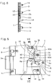
- a lock plate 1 can be seen, on the front, angled edge of which a face plate 2 is fastened.
- the locking shaft 3 is mounted so as to be longitudinally displaceable via elongated holes 3b on guide pins 1a which are fastened to the lock plate 1.
- the longitudinal shaft 4a is guided by guide pins 1b, which are also arranged on the lock plate 1.
- the lock plate 1 carries threaded bushings 1c, which are used for the detachable fastening of the lock cover, not shown in the drawings.
- the bolt consisting of bolt shaft 3 and bolt head 3a is actuated by a key S, which is shown in dashed lines in FIGS. 1 to 4 and is plugged onto a key pin 1d arranged on the lock plate 1.
- This key S which is designed as a double-bit key in the exemplary embodiment, acts on locking tumblers 5 which are mounted on the lock plate 1 in an adjustable manner via elongated holes 5c on the guide pins 1a provided for guiding the locking shaft 3a.
- the locking tumblers 5 are designed to interact with the key bit of the key S with a tumbler channel 5a. In the area of this tumbler channel 5a, two stop pins 1e are arranged on the lock plate 1, which prevent the key S from being rotated in the wrong direction of rotation.
- each locking tumbler 5 interacts via a coupling channel 5b with a coupling piece 6a of a changeover tumbler 6, which are also height-adjustable via elongated holes 6b on bearing pins 3c of the locking shaft 3.
- each changeover tumbler 6 interacts with a locking tumbler 7, which is held in the closed state of the lock on a retaining pin 8, which in turn is fixedly arranged on the lock plate 1.
- the locking tumblers 7 are guided via elongated holes 7a on guide pins 9a of a support plate 9 which is arranged below the locking shaft 3 between this locking shaft 3 and the lock plate 1 and with the guide pins 9a in elongated holes 3e of the locking shaft 3 engages.
- This support plate 9 is loaded by a tension spring 9b, which is arranged between a guide pin 9a of the support plate 9 and a spring mandrel 3f fastened on the locking shaft 3.
- the latch 4 is actuated either via the locking lug of a profile cylinder, not shown, which is inserted into a locking cylinder opening 1f shown in the drawings in the lock plate 1 and in the lock cover, not shown, or via a change 10, which is on a bearing mandrel 3g on the bolt shaft 3 is pivotally mounted. At the upper end, the change 10 is loaded counterclockwise by a return spring 11.
- the key S In order to be able to retract the latch 4 against the force of a latch spring 4c by means of the change 10 in the half-open position of the lock according to FIG. 2, the key S must be removed from the lock and rotated by 180 ° and put back on the key pin 1d. During the subsequent rotation of the key S in a clockwise direction according to FIG. 3, the key bit strikes a lever 12 which is pivotably mounted on a bearing pin 3h of the locking shaft 3. This lever 12 comes into contact with the described key rotation on a stop pin 10a of the change 10, so that with a further turn of the key according to FIG. 4 the upper end of the change 10 via a stop bolt 4b fastened on the drop shaft 4a, the latch 4 into the position shown in FIG 4 retracts the position shown against the force of both the latch spring 4c and the return spring 11.
- a prerequisite for this retraction movement of the trap 4 is that the complete tumbler package comprising locking tumblers 5, changeover tumblers 6 and locking tumblers 7 according to FIG. 3 has been raised beforehand via the key bit of the correct key S, so that one fastened on a removable plate 13 Interchangeable pin 13a in the respective closure, correspondingly aligned incisions 7b of the locking tumblers 7 can occur.
- the interchangeable plate 13 is guided in a longitudinally displaceable manner by means of elongated holes 13b on bearing pins 1g of the lock plate 1 and is longitudinally displaced via an elongated hole 10b in alternation 10 by a driving mandrel 13c fastened on the interchangeable plate 13.
- An actuation of the change 10 by the key S is therefore only possible if the three-part tumblers have been properly classified according to the respective locking, which is why one speaks of a secured change 10.
- a holder 14 is pivotally mounted on a bearing pin 1h of the lock plate 1, which is loaded by a leg spring 14a and engages with stops in corresponding recesses or behind corresponding stop edges of the bolt shaft 3.
- This retainer 14 is raised by at least one of the locking tumblers 5 against the force of the leg spring 14a when the locking shaft 3 is to be transferred from the respective end position into the other end position.
- the locking tumblers 5 are first raised by the key S corresponding to the respective locking, so that the coupling pins 6a of the switching tumblers 6 together with a further key rotation the bolt shaft 3 can be moved back. With the locking tumblers 5, the retainer 14 was raised so that the locking shaft 3 is released for this retraction movement.
- the latch 4 can be pulled back against the force of the latch spring 4c by the locking lug of the profile cylinder not shown in FIG. 2. This retraction movement of the latch 4 is thus independent of the locking mechanism actuated by the key S.
- the rear part of the bolt closure R h necessary to retract the bolt shaft 3 is trained directly on the locking shaft 3.
- the part of the bolt lock R w required to actuate the change 10 when the bolt is withdrawn is located on the front of the lever 12, whereas the back of this lever 12 serves as the front part R v of the bolt lock when the bolt shaft 3 is shown in FIG. 4 open position of the lock is to be transferred back to the closed position shown in FIG. 1.
- the bolt closure is formed on the one hand by a recess A in the bolt shaft 3 and on the other hand by the free end of the lever 12 protruding into this recess A, which can be pivoted to a limited extent about the bearing mandrel 3h arranged on the bolt shaft 3 .
- this lever 12 (as best seen in FIG. 6) lies between the lock plate 1 and the change 10, which in turn lies below the locking shaft 3.
- the front, in the recess A of the locking shaft 3 protruding part of the change 12 has a considerably greater strength, so that a stop surface 12b is created, with which the lever 12 in its front, shown in FIGS. 5 and 7 at the the upper edge of the recess A.
- This stop surface 12b can be seen both in FIG. 8 and in FIG. 6. It limits the pivoting movement of the lever 12 in a clockwise direction.
- the key S shown in dashed lines in FIG. 5 is turned clockwise.
- its longer key bit takes the locking shaft 3 with it over the rear part of the locking lock R h until it has reached the position shown in FIG. 7.
- the change to retract the latch 4 is now to be actuated with the key S, it is necessary to remove the key S from the key mandrel 1d and to replace it rotated by 180 °.
- the latch 4 can then be actuated by turning the key S clockwise. As can be seen from FIG.
- the latch 4 returns to its out of the faceplate 2 due to its loading by the latch spring 4c outstanding position.
- the change 10 and the lever 12 also return from their position shown in FIG. 8 to their initial position according to FIG. 7, with the aid of the return spring 11 or spring 12a.
Landscapes
- Lock And Its Accessories (AREA)
Applications Claiming Priority (2)
| Application Number | Priority Date | Filing Date | Title |
|---|---|---|---|
| DE4431925 | 1994-09-08 | ||
| DE4431925A DE4431925C2 (de) | 1994-09-08 | 1994-09-08 | Schloß für Gefängnistüren |
Publications (2)
| Publication Number | Publication Date |
|---|---|
| EP0701037A1 true EP0701037A1 (fr) | 1996-03-13 |
| EP0701037B1 EP0701037B1 (fr) | 1998-04-29 |
Family
ID=6527667
Family Applications (1)
| Application Number | Title | Priority Date | Filing Date |
|---|---|---|---|
| EP95113819A Expired - Lifetime EP0701037B1 (fr) | 1994-09-08 | 1995-09-02 | Serrure pour portes de prison |
Country Status (3)
| Country | Link |
|---|---|
| EP (1) | EP0701037B1 (fr) |
| AT (1) | ATE165642T1 (fr) |
| DE (1) | DE4431925C2 (fr) |
Families Citing this family (6)
| Publication number | Priority date | Publication date | Assignee | Title |
|---|---|---|---|---|
| DE19738243C2 (de) * | 1997-09-02 | 2001-07-12 | Steinbach & Vollmann | Schloß für Sicherheitstüren |
| DE19738242C2 (de) * | 1997-09-02 | 2002-04-11 | Steinbach & Vollmann | Schloß für Sicherheitstüren |
| DE10156632C1 (de) * | 2001-11-17 | 2003-06-12 | Steinbach & Vollmann | Türschloss, insbesondere Einsteckschloss |
| EP1347130A1 (fr) * | 2002-03-22 | 2003-09-24 | Steinbach & Vollmann GmbH & Co. | Serrure pour portes de sécurité |
| DE50215038D1 (de) * | 2002-03-22 | 2011-06-16 | Steinbach & Vollmann | Schloss für Sicherheitstüren |
| CN1916337B (zh) * | 2006-09-07 | 2011-06-08 | 陆昱森 | 具有旋式弹子锁头的自动安全门锁 |
Citations (2)
| Publication number | Priority date | Publication date | Assignee | Title |
|---|---|---|---|---|
| DE1001152B (de) * | 1952-07-01 | 1957-01-17 | Niederhoff & Sieper G M B H | Tuerschloss mit zwei unabhaengigen Drueckern |
| DE4143292A1 (de) * | 1991-12-24 | 1993-07-01 | Fliether Karl Gmbh & Co | Schloss, insbesondere einsteckschloss |
Family Cites Families (3)
| Publication number | Priority date | Publication date | Assignee | Title |
|---|---|---|---|---|
| DE599928C (de) * | 1934-07-12 | Paul Herbst | Schloss mit einem durch Zuhaltungen gesperrten Fallenwechsel | |
| DE3513265C2 (de) * | 1985-04-13 | 1994-03-03 | Steinbach & Vollmann | Schloß für Justizvollzugsanstalten |
| DE3706007C2 (de) * | 1987-02-25 | 1996-05-23 | Melchert Beschlaege | Türschloß |
-
1994
- 1994-09-08 DE DE4431925A patent/DE4431925C2/de not_active Expired - Fee Related
-
1995
- 1995-09-02 EP EP95113819A patent/EP0701037B1/fr not_active Expired - Lifetime
- 1995-09-02 AT AT95113819T patent/ATE165642T1/de not_active IP Right Cessation
Patent Citations (2)
| Publication number | Priority date | Publication date | Assignee | Title |
|---|---|---|---|---|
| DE1001152B (de) * | 1952-07-01 | 1957-01-17 | Niederhoff & Sieper G M B H | Tuerschloss mit zwei unabhaengigen Drueckern |
| DE4143292A1 (de) * | 1991-12-24 | 1993-07-01 | Fliether Karl Gmbh & Co | Schloss, insbesondere einsteckschloss |
Also Published As
| Publication number | Publication date |
|---|---|
| EP0701037B1 (fr) | 1998-04-29 |
| ATE165642T1 (de) | 1998-05-15 |
| DE4431925C2 (de) | 1996-12-12 |
| DE4431925A1 (de) | 1996-03-14 |
Similar Documents
| Publication | Publication Date | Title |
|---|---|---|
| EP0911470B1 (fr) | Dispositif de verrouillage | |
| EP1932989B1 (fr) | Système de fermeture pour portes, fenêtres ou analogues, en particulier crémone-serrure à fonction d'urgence et de verrouillage à plusieurs points | |
| EP1970507B1 (fr) | Serrure anti-panique | |
| DE19610346A1 (de) | Schließvorrichtung | |
| DE2840285A1 (de) | Fallenriegelschloss | |
| EP2264268B2 (fr) | Crémone serrure | |
| DE19514742A1 (de) | Rohrrahmenschloß | |
| EP0807736B1 (fr) | Serrure encastrée | |
| EP0204944B1 (fr) | Serrure de secours avec pêne, en particulier pour portes avec châssis tubulaire | |
| EP0653535B1 (fr) | Serrure | |
| EP0701037B1 (fr) | Serrure pour portes de prison | |
| DE3940393C2 (de) | Sicherheitsschloß | |
| DE2738746C3 (de) | Auslösevorrichtung für ein Paniktürschloß mit Falle und Riegel | |
| EP3144455B1 (fr) | Dispositif de verrouillage | |
| EP0779403B1 (fr) | Serrure de sécurité | |
| DE19826869C1 (de) | Schloß für Hochsicherheitstüren | |
| DE69722357T2 (de) | Verbesserungen an Schlössern | |
| EP0298292B1 (fr) | Serrure de porte à pêne et demi-tour coulissants | |
| EP0913550B2 (fr) | Crémone-serrure | |
| DE19738244C2 (de) | Schloß für Sicherheitstüren | |
| DE3042611C2 (fr) | ||
| EP0701034B1 (fr) | Serrure pour porte de prison | |
| DE2605763C3 (de) | Treibstangenschloß mit Falle | |
| DE29909660U1 (de) | Türverschluß | |
| DE4431923C1 (de) | Schloß für Gefängnistüren |
Legal Events
| Date | Code | Title | Description |
|---|---|---|---|
| PUAI | Public reference made under article 153(3) epc to a published international application that has entered the european phase |
Free format text: ORIGINAL CODE: 0009012 |
|
| AK | Designated contracting states |
Kind code of ref document: A1 Designated state(s): AT FR GB NL SE |
|
| 17P | Request for examination filed |
Effective date: 19960115 |
|
| GRAG | Despatch of communication of intention to grant |
Free format text: ORIGINAL CODE: EPIDOS AGRA |
|
| GRAG | Despatch of communication of intention to grant |
Free format text: ORIGINAL CODE: EPIDOS AGRA |
|
| GRAH | Despatch of communication of intention to grant a patent |
Free format text: ORIGINAL CODE: EPIDOS IGRA |
|
| 17Q | First examination report despatched |
Effective date: 19971017 |
|
| GRAH | Despatch of communication of intention to grant a patent |
Free format text: ORIGINAL CODE: EPIDOS IGRA |
|
| GRAA | (expected) grant |
Free format text: ORIGINAL CODE: 0009210 |
|
| AK | Designated contracting states |
Kind code of ref document: B1 Designated state(s): AT FR GB NL SE |
|
| REF | Corresponds to: |
Ref document number: 165642 Country of ref document: AT Date of ref document: 19980515 Kind code of ref document: T |
|
| ET | Fr: translation filed | ||
| GBT | Gb: translation of ep patent filed (gb section 77(6)(a)/1977) |
Effective date: 19980430 |
|
| PLBE | No opposition filed within time limit |
Free format text: ORIGINAL CODE: 0009261 |
|
| STAA | Information on the status of an ep patent application or granted ep patent |
Free format text: STATUS: NO OPPOSITION FILED WITHIN TIME LIMIT |
|
| 26N | No opposition filed | ||
| PGFP | Annual fee paid to national office [announced via postgrant information from national office to epo] |
Ref country code: GB Payment date: 20010814 Year of fee payment: 7 |
|
| PGFP | Annual fee paid to national office [announced via postgrant information from national office to epo] |
Ref country code: AT Payment date: 20010824 Year of fee payment: 7 |
|
| PGFP | Annual fee paid to national office [announced via postgrant information from national office to epo] |
Ref country code: SE Payment date: 20010827 Year of fee payment: 7 Ref country code: NL Payment date: 20010827 Year of fee payment: 7 |
|
| PGFP | Annual fee paid to national office [announced via postgrant information from national office to epo] |
Ref country code: FR Payment date: 20010904 Year of fee payment: 7 |
|
| REG | Reference to a national code |
Ref country code: GB Ref legal event code: IF02 |
|
| PG25 | Lapsed in a contracting state [announced via postgrant information from national office to epo] |
Ref country code: GB Free format text: LAPSE BECAUSE OF NON-PAYMENT OF DUE FEES Effective date: 20020902 Ref country code: AT Free format text: LAPSE BECAUSE OF NON-PAYMENT OF DUE FEES Effective date: 20020902 |
|
| PG25 | Lapsed in a contracting state [announced via postgrant information from national office to epo] |
Ref country code: SE Free format text: LAPSE BECAUSE OF NON-PAYMENT OF DUE FEES Effective date: 20020903 |
|
| PG25 | Lapsed in a contracting state [announced via postgrant information from national office to epo] |
Ref country code: NL Free format text: LAPSE BECAUSE OF NON-PAYMENT OF DUE FEES Effective date: 20030401 |
|
| GBPC | Gb: european patent ceased through non-payment of renewal fee |
Effective date: 20020902 |
|
| EUG | Se: european patent has lapsed | ||
| PG25 | Lapsed in a contracting state [announced via postgrant information from national office to epo] |
Ref country code: FR Free format text: LAPSE BECAUSE OF NON-PAYMENT OF DUE FEES Effective date: 20030603 |
|
| REG | Reference to a national code |
Ref country code: FR Ref legal event code: ST |