EP0701065A2 - Cylindre à pression pour hydraulique à haute pression - Google Patents
Cylindre à pression pour hydraulique à haute pression Download PDFInfo
- Publication number
- EP0701065A2 EP0701065A2 EP95112898A EP95112898A EP0701065A2 EP 0701065 A2 EP0701065 A2 EP 0701065A2 EP 95112898 A EP95112898 A EP 95112898A EP 95112898 A EP95112898 A EP 95112898A EP 0701065 A2 EP0701065 A2 EP 0701065A2
- Authority
- EP
- European Patent Office
- Prior art keywords
- proviso
- use according
- pressure cylinder
- end components
- tube
- Prior art date
- Legal status (The legal status is an assumption and is not a legal conclusion. Google has not performed a legal analysis and makes no representation as to the accuracy of the status listed.)
- Granted
Links
- 239000004033 plastic Substances 0.000 claims abstract description 7
- 229920003023 plastic Polymers 0.000 claims abstract description 7
- 239000000835 fiber Substances 0.000 claims abstract description 5
- 229910052751 metal Inorganic materials 0.000 claims abstract description 4
- 239000002184 metal Substances 0.000 claims abstract description 4
- 229920002430 Fibre-reinforced plastic Polymers 0.000 claims description 10
- 239000011151 fibre-reinforced plastic Substances 0.000 claims description 10
- 239000002131 composite material Substances 0.000 claims description 8
- 229910000838 Al alloy Inorganic materials 0.000 claims description 6
- 229910000861 Mg alloy Inorganic materials 0.000 claims description 6
- 230000015572 biosynthetic process Effects 0.000 claims description 6
- 238000005755 formation reaction Methods 0.000 claims description 6
- 229910000851 Alloy steel Inorganic materials 0.000 claims description 3
- 229910045601 alloy Inorganic materials 0.000 claims description 3
- 239000000956 alloy Substances 0.000 claims description 3
- XAGFODPZIPBFFR-UHFFFAOYSA-N aluminium Chemical compound [Al] XAGFODPZIPBFFR-UHFFFAOYSA-N 0.000 claims description 3
- 230000002787 reinforcement Effects 0.000 claims 2
- 239000004760 aramid Substances 0.000 claims 1
- 229920003235 aromatic polyamide Polymers 0.000 claims 1
- 239000004918 carbon fiber reinforced polymer Substances 0.000 claims 1
- 239000011152 fibreglass Substances 0.000 claims 1
- 238000010276 construction Methods 0.000 description 2
- 238000004519 manufacturing process Methods 0.000 description 2
- 229910000831 Steel Inorganic materials 0.000 description 1
- 239000000853 adhesive Substances 0.000 description 1
- 230000001070 adhesive effect Effects 0.000 description 1
- 230000000052 comparative effect Effects 0.000 description 1
- 230000006735 deficit Effects 0.000 description 1
- 230000000694 effects Effects 0.000 description 1
- 230000002706 hydrostatic effect Effects 0.000 description 1
- 239000000463 material Substances 0.000 description 1
- 230000036316 preload Effects 0.000 description 1
- 239000010959 steel Substances 0.000 description 1
Images

Classifications
-
- F—MECHANICAL ENGINEERING; LIGHTING; HEATING; WEAPONS; BLASTING
- F15—FLUID-PRESSURE ACTUATORS; HYDRAULICS OR PNEUMATICS IN GENERAL
- F15B—SYSTEMS ACTING BY MEANS OF FLUIDS IN GENERAL; FLUID-PRESSURE ACTUATORS, e.g. SERVOMOTORS; DETAILS OF FLUID-PRESSURE SYSTEMS, NOT OTHERWISE PROVIDED FOR
- F15B15/00—Fluid-actuated devices for displacing a member from one position to another; Gearing associated therewith
- F15B15/08—Characterised by the construction of the motor unit
- F15B15/14—Characterised by the construction of the motor unit of the straight-cylinder type
- F15B15/1423—Component parts; Constructional details
- F15B15/1433—End caps
-
- F—MECHANICAL ENGINEERING; LIGHTING; HEATING; WEAPONS; BLASTING
- F15—FLUID-PRESSURE ACTUATORS; HYDRAULICS OR PNEUMATICS IN GENERAL
- F15B—SYSTEMS ACTING BY MEANS OF FLUIDS IN GENERAL; FLUID-PRESSURE ACTUATORS, e.g. SERVOMOTORS; DETAILS OF FLUID-PRESSURE SYSTEMS, NOT OTHERWISE PROVIDED FOR
- F15B15/00—Fluid-actuated devices for displacing a member from one position to another; Gearing associated therewith
- F15B15/08—Characterised by the construction of the motor unit
- F15B15/14—Characterised by the construction of the motor unit of the straight-cylinder type
- F15B15/1423—Component parts; Constructional details
- F15B15/1428—Cylinders
-
- F—MECHANICAL ENGINEERING; LIGHTING; HEATING; WEAPONS; BLASTING
- F15—FLUID-PRESSURE ACTUATORS; HYDRAULICS OR PNEUMATICS IN GENERAL
- F15B—SYSTEMS ACTING BY MEANS OF FLUIDS IN GENERAL; FLUID-PRESSURE ACTUATORS, e.g. SERVOMOTORS; DETAILS OF FLUID-PRESSURE SYSTEMS, NOT OTHERWISE PROVIDED FOR
- F15B15/00—Fluid-actuated devices for displacing a member from one position to another; Gearing associated therewith
- F15B15/08—Characterised by the construction of the motor unit
- F15B15/14—Characterised by the construction of the motor unit of the straight-cylinder type
- F15B15/149—Fluid interconnections, e.g. fluid connectors, passages
-
- F—MECHANICAL ENGINEERING; LIGHTING; HEATING; WEAPONS; BLASTING
- F15—FLUID-PRESSURE ACTUATORS; HYDRAULICS OR PNEUMATICS IN GENERAL
- F15B—SYSTEMS ACTING BY MEANS OF FLUIDS IN GENERAL; FLUID-PRESSURE ACTUATORS, e.g. SERVOMOTORS; DETAILS OF FLUID-PRESSURE SYSTEMS, NOT OTHERWISE PROVIDED FOR
- F15B2215/00—Fluid-actuated devices for displacing a member from one position to another
- F15B2215/30—Constructional details thereof
- F15B2215/305—Constructional details thereof characterised by the use of special materials
Definitions
- the invention relates to an actuator of the high-pressure hydraulic system, which has at least one pressure cylinder in which at least one metallic actuating piston with a piston rod is guided.
- the pressure cylinder is generally provided with end components which are pushed into the pressure cylinder, held by tie rods and sealed against the pressure cylinder.
- one of the end components is a closed component and the other has a bore in which the piston rod is guided in a sealed manner.
- the piston can also have a piston rod on both sides, which are guided in both end components.
- several pistons can also be provided in the pressure cylinder. It can be in the actuator z. B. act as a single or double acting actuator.
- the piston of such an actuator generally has molded-on metallic piston rings or polymeric sliding bands which effect the guidance.
- a soft seal can be arranged between the piston rings.
- high pressure denotes a hydrostatic pressure of over 100 bar, for. B. from 400 to 500 bar.
- the pressure cylinder is a component made of steel, which has a wall thickness corresponding to the pressure of the high-pressure medium. This makes the actuator a heavy weight unit.
- the invention is based on the technical problem of creating an actuating cylinder of the design described at the outset and of the purpose described at the outset, which is much lighter with the same power and the same pressure as the high-pressure hydraulics and can therefore be used in particular in aircraft, in ships and other vehicles without that a disturbing increase in weight would have to be accepted.
- the subject of the invention is the use of a composite unit consisting of a metallic liner in the form of a circular cylindrical inner tube and a fiber-reinforced plastic tube placed thereon as a pressure cylinder of an actuator of the high-pressure hydraulics, which has at least one such pressure cylinder, into which a metallic actuating piston with a piston rod works in the inner tube, with the proviso that the pressure cylinder has metallic end components which are fitted with a cylindrical fitting into the metallic inner liner of the pressure cylinder and are connected to it in a sealed manner, and project with collar formations above the pressure cylinder, at least one end component having a bore and the piston rod being guided therein , with the proviso that the supply and discharge of the high pressure medium takes place via channels in the end components and with the proviso that the two end components are connected by tie rods, which are held in the collar training.
- Actuators that have a pressure cylinder made of a metallic liner and a casing made of fiber-proven plastic are known (WO 93/23675).
- the metallic liner and the casing are not designed as circular cylindrical tubes. The manufacture is therefore complex.
- Actuators are also known which have a pressure cylinder made of an inner tube and an outer tube (WO 91/11319), both of which consist of fiber-proven plastic. These actuators are not very suitable for high pressure hydraulics.
- the pressure cylinder consists of a thin-walled inner tube and a fiber-reinforced plastic tube can exist if the requirements described in claim 1 are realized and if the connection of the pressure cylinder to the end components and the adjustment of the tie rods stabilizes the pressure cylinder against deformations caused by high pressure medium.
- the high-pressure medium in the outer tube which is connected to the end components, would easily produce tensile forces running in the circumferential direction, the high-pressure medium increasing the diameter of the outer tube. This would result in an impairment of the tightness between the piston and the inner tube.
- this disruptive deformation can be prevented if a fiber composite outer tube with a high modulus of elasticity is used in the circumferential direction in the manner described.
- the outer jacket is under slight tension when the high-pressure medium is not present.
- the pretension can also be set up without a force-locking connection between the end components and the inner jacket in such a way that disruptive deformations of the pressure cylinder do not occur under the pressure of the high-pressure medium.
- a composite assembly consisting of a metallic liner in the form of a circular cylindrical inner tube and a plastic-fiber-reinforced plastic tube placed thereon designates an aggregate of these two components, regardless of whether the fiber-reinforced plastic tube is connected to the metallic inner tube via a shrink connection or via an adhesive connection is.
- the composite can also be given by the outer tube being wound directly onto the inner tube, the different thermal expansions of the two materials, metal on the one hand and fiber-reinforced plastic on the other, being able to be used in a targeted manner.
- the teaching of the invention leads to an actuator of very light construction, which is nevertheless able to absorb extremely high pressures of the high-pressure medium and can produce corresponding actuating forces.
- the actuators constructed according to the teaching of the invention are furthermore distinguished by a long service life. They are nonetheless easy to manufacture than mass-produced items.
- the pressure cylinder does not absorb axial forces caused by pressure medium. These are only taken up by the tie rod, which does not hinder deformation in the circumferential or radial direction. The preload caused by the tie rods is low. Buckling deformations of the printing cylinder are avoided.
- the highly rigid fiber composite pipe counteracts an annoying increase in diameter as a result of the internal pressure.
- the collar designs can be designed as a circumferential collar and molded onto the adapters. But there is also the possibility to design the collar recesses as collar sections and to form them onto the adapters. Depending on the design of the federal government training, one could also speak of flanges. According to a preferred embodiment of the invention Drawbars designed as bolts and have these nuts, via which the tensile force can be adjusted.
- the fiber-reinforced plastic tube is expediently designed in detail as it results from the claims 9 to 14.
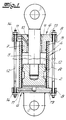
- the actuators shown in the figures are actuators for the high pressure hydraulics. They have at least one pressure cylinder 1 in which a metallic actuating piston 2 with a piston rod 3 is guided.
- FIGS. 1 and 2 From a comparative view of FIGS. 1 and 2 it can be seen that as the pressure cylinder 1, a composite unit made of a metallic liner in the form of a circular cylindrical inner tube 4 and one placed thereon fiber-reinforced plastic tube 5 is executed.
- the plastic tube forms the outer tube.
- the pressure cylinder 1 has metallic end components 6 which are fitted into the pressure cylinder 1 with a cylindrical fitting piece and are connected to it in a sealed manner.
- the end components 6 project with collar formations 8 above the pressure cylinder.
- the arrangement is such that at least one end component 6 has a bore 9 in which the piston rod 3 is guided.
- Usual seals 10 are provided.
- the high-pressure medium is supplied and removed via channels 11 in these end components 6.
- the two end components 6 are connected by tie rods 12 which are held in the collar 8. You are e.g. B. passed through corresponding holes 13.
- the pressure cylinder 1 is stabilized against deformations caused by high pressure medium.
- the pressure cylinder 1 may be under the pressure of a high pressure medium. It can be seen that the pressure cylinder 1 does not have deformations caused by high pressure medium.
- the inner tube 4 is a drawn tube in the form of a precision tube with a wall thickness of less than 1 mm. It was for reasons of scale in Fig. 1 with a drawn excessively thick wall.
- the actuating piston 2 and / or the end components 6 consist of an alloy from the group of steel alloys, aluminum alloys, magnesium alloys, aluminum / magnesium alloys.
- the end components 6 may be positively connected to the inner tube 4, as is indicated in FIG. 1.
- the composite also acts as a seal.
- the collar designs 8 are designed as a circumferential collar, which has a flange-like character in the exemplary embodiment.
- the tie rods 12 are bolts which have nuts 14, via which the tensile force can be adjusted.
- the construction of the plastic tube 5 can only be hinted at. It is designed in detail as it corresponds to claims 9 to 14.
- an actuator constructed according to the teaching of the invention can also have an actuating piston 2 with two piston rods 3 or two actuating pistons 2.
Landscapes
- Engineering & Computer Science (AREA)
- Physics & Mathematics (AREA)
- Fluid Mechanics (AREA)
- Mechanical Engineering (AREA)
- General Engineering & Computer Science (AREA)
- Actuator (AREA)
Applications Claiming Priority (2)
| Application Number | Priority Date | Filing Date | Title |
|---|---|---|---|
| DE19944430502 DE4430502C2 (de) | 1994-08-27 | 1994-08-27 | Verwendung eines Verbundaggregates aus einem Liner und einem faserverstärkten Kunststoffrohr als Druckzylinder eines Stelltriebes der Hochdruckhydraulik |
| DE4430502 | 1994-08-27 |
Publications (3)
| Publication Number | Publication Date |
|---|---|
| EP0701065A2 true EP0701065A2 (fr) | 1996-03-13 |
| EP0701065A3 EP0701065A3 (fr) | 1996-12-27 |
| EP0701065B1 EP0701065B1 (fr) | 2000-03-01 |
Family
ID=6526745
Family Applications (1)
| Application Number | Title | Priority Date | Filing Date |
|---|---|---|---|
| EP19950112898 Expired - Lifetime EP0701065B1 (fr) | 1994-08-27 | 1995-08-17 | Cylindre à pression pour hydraulique à haute pression |
Country Status (4)
| Country | Link |
|---|---|
| EP (1) | EP0701065B1 (fr) |
| DE (1) | DE4430502C2 (fr) |
| DK (1) | DK0701065T3 (fr) |
| ES (1) | ES2145858T3 (fr) |
Cited By (9)
| Publication number | Priority date | Publication date | Assignee | Title |
|---|---|---|---|---|
| DE19649133C1 (de) * | 1996-11-27 | 1998-03-05 | Dornier Gmbh | Hydraulik-Zylinder |
| EP0841490A2 (fr) | 1996-11-05 | 1998-05-13 | Deutsches Zentrum für Luft- und Raumfahrt e.V. | Dispositif pour l'introduction de force |
| WO1998022715A3 (fr) * | 1996-11-16 | 1998-09-03 | Lingk & Sturzebecher Leichtbau | Tige de piston pour piston de regulation d'un reducteur de positionnement |
| WO2006055997A1 (fr) | 2004-11-25 | 2006-06-01 | HÖLZL, Margit | Cylindre pour l'hydraulique haute pression |
| US7984731B2 (en) | 2007-11-13 | 2011-07-26 | Parker-Hannifin Corporation | Lightweight high pressure repairable piston tie rod composite accumulator |
| US8262825B2 (en) | 2007-09-11 | 2012-09-11 | Parker Hannifin Gmbh | End-fittings for composite tubes, method for joining fittings to the ends of composite tubes and composite tubes incorporating end-fitting |
| US8695643B2 (en) | 2007-11-08 | 2014-04-15 | Parker-Hannifin Corporation | Lightweight high pressure repairable piston composite accumulator with slip flange |
| DE102009014813B4 (de) * | 2009-03-25 | 2014-10-23 | Festo Ag & Co. Kg | Linearantrieb |
| EP4545807A1 (fr) * | 2023-10-23 | 2025-04-30 | Goodrich Actuation Systems SAS | Ensemble actionneur |
Families Citing this family (13)
| Publication number | Priority date | Publication date | Assignee | Title |
|---|---|---|---|---|
| DE19732934A1 (de) * | 1997-07-31 | 1999-02-04 | Mannesmann Rexroth Ag | Hydraulischer Zylinder in Zugankerbauart, insbesondere für Kleinpressen |
| DE19811657A1 (de) * | 1998-03-18 | 1999-09-23 | Schaeffler Waelzlager Ohg | Hydraulisch betätigbares Ausrücksystem |
| EP0987446A1 (fr) * | 1998-09-15 | 2000-03-22 | Lingk & Sturzebecher Leichtbau GmbH | Vérin hydraulique |
| DE19925600A1 (de) * | 1999-06-04 | 2000-12-14 | Sbs Sondermaschinen Gmbh | Leichtbau-Hydraulikzylinder mit Zugankern |
| DE102004008523B4 (de) * | 2004-02-20 | 2007-02-01 | Liebherr-Aerospace Lindenberg Gmbh | Verfahren zur Herstellung eines Druckzylinders und Kolbenstange für Aktuatoren oder Stoßdämpfer und Verfahren zu deren Herstellung |
| DE102006047413B4 (de) * | 2005-10-06 | 2014-01-16 | Technische Universität Dresden | Zylinder aus Faserverbundwerkstoff mit metallischen Flanschkomponenten sowie Verfahren zur Herstellung |
| DE102009029299B4 (de) | 2009-09-09 | 2015-12-31 | Leichtbau-Zentrum Sachsen Gmbh | Schwingungsdämpfer |
| AT512703B1 (de) * | 2012-04-12 | 2014-06-15 | Neuson Hydrotec Gmbh | Kolben-Zylindereinheit |
| DE102015211545B3 (de) * | 2015-06-23 | 2016-11-10 | Innotec Lightweight Engineering & Polymer Technology Gmbh | Zylinderrohr für einen Hydraulik- oder Pneumatikzylinder |
| DE102017000857A1 (de) * | 2017-01-31 | 2018-08-02 | Liebherr-Components Kirchdorf GmbH | Zylinder-Kolben-Vorrichtung |
| EP3546787B1 (fr) * | 2018-03-27 | 2021-02-24 | Aida Engineering, Ltd. | Dispositif de coussin de gaz |
| DE102023200931B4 (de) * | 2023-02-06 | 2025-05-08 | Fraunhofer-Gesellschaft zur Förderung der angewandten Forschung eingetragener Verein | Hydraulikzylinder, Verfahren zu seiner Herstellung und damit ausgestatteter Bohrhammer |
| DE102023205446A1 (de) * | 2023-06-13 | 2024-12-19 | Zf Friedrichshafen Ag | Verstellbare Dämpfventileinrichtung |
Citations (2)
| Publication number | Priority date | Publication date | Assignee | Title |
|---|---|---|---|---|
| WO1991011319A1 (fr) | 1990-01-25 | 1991-08-08 | Hitachi Construction Machinery Co., Ltd. | Recipient de pression en materiau composite |
| WO1993023675A1 (fr) | 1992-05-13 | 1993-11-25 | Hr Textron Inc. | Cylindre composite pour verins hydrauliques d'avions |
Family Cites Families (7)
| Publication number | Priority date | Publication date | Assignee | Title |
|---|---|---|---|---|
| US3286737A (en) * | 1963-08-01 | 1966-11-22 | Dowsmith Inc | Wear-resistant article and method of making the same |
| DE6916307U (de) * | 1969-04-23 | 1969-09-04 | Kloeckner Werke Ag | Druckzylinder |
| FR2554876B1 (fr) * | 1983-11-10 | 1988-02-26 | Peugeot Aciers Et Outillage | Verin a base de materiaux composites |
| IT1185613B (it) * | 1985-05-30 | 1987-11-12 | Magnaghi Cleodinamica Spa | Accumulatore di pressione gas-olio con struttura in materiali compositi per circuiti idraulici di velivoli |
| US4885981A (en) * | 1988-04-08 | 1989-12-12 | General Signal Corporation | Spring return cylinder actuator |
| DE9207582U1 (de) * | 1992-06-04 | 1992-08-20 | Festo KG, 7300 Esslingen | Gehäuse für einen Arbeitszylinder |
| JPH0829265B2 (ja) * | 1992-12-09 | 1996-03-27 | 崇 川合 | 粒体選別装置 |
-
1994
- 1994-08-27 DE DE19944430502 patent/DE4430502C2/de not_active Expired - Lifetime
-
1995
- 1995-08-17 EP EP19950112898 patent/EP0701065B1/fr not_active Expired - Lifetime
- 1995-08-17 DK DK95112898T patent/DK0701065T3/da active
- 1995-08-17 ES ES95112898T patent/ES2145858T3/es not_active Expired - Lifetime
Patent Citations (2)
| Publication number | Priority date | Publication date | Assignee | Title |
|---|---|---|---|---|
| WO1991011319A1 (fr) | 1990-01-25 | 1991-08-08 | Hitachi Construction Machinery Co., Ltd. | Recipient de pression en materiau composite |
| WO1993023675A1 (fr) | 1992-05-13 | 1993-11-25 | Hr Textron Inc. | Cylindre composite pour verins hydrauliques d'avions |
Cited By (10)
| Publication number | Priority date | Publication date | Assignee | Title |
|---|---|---|---|---|
| EP0841490A2 (fr) | 1996-11-05 | 1998-05-13 | Deutsches Zentrum für Luft- und Raumfahrt e.V. | Dispositif pour l'introduction de force |
| DE19645467A1 (de) * | 1996-11-05 | 1998-05-14 | Deutsch Zentr Luft & Raumfahrt | Vorrichtung zur Krafteinleitung |
| WO1998022715A3 (fr) * | 1996-11-16 | 1998-09-03 | Lingk & Sturzebecher Leichtbau | Tige de piston pour piston de regulation d'un reducteur de positionnement |
| DE19649133C1 (de) * | 1996-11-27 | 1998-03-05 | Dornier Gmbh | Hydraulik-Zylinder |
| WO2006055997A1 (fr) | 2004-11-25 | 2006-06-01 | HÖLZL, Margit | Cylindre pour l'hydraulique haute pression |
| US8262825B2 (en) | 2007-09-11 | 2012-09-11 | Parker Hannifin Gmbh | End-fittings for composite tubes, method for joining fittings to the ends of composite tubes and composite tubes incorporating end-fitting |
| US8695643B2 (en) | 2007-11-08 | 2014-04-15 | Parker-Hannifin Corporation | Lightweight high pressure repairable piston composite accumulator with slip flange |
| US7984731B2 (en) | 2007-11-13 | 2011-07-26 | Parker-Hannifin Corporation | Lightweight high pressure repairable piston tie rod composite accumulator |
| DE102009014813B4 (de) * | 2009-03-25 | 2014-10-23 | Festo Ag & Co. Kg | Linearantrieb |
| EP4545807A1 (fr) * | 2023-10-23 | 2025-04-30 | Goodrich Actuation Systems SAS | Ensemble actionneur |
Also Published As
| Publication number | Publication date |
|---|---|
| EP0701065B1 (fr) | 2000-03-01 |
| ES2145858T3 (es) | 2000-07-16 |
| DK0701065T3 (da) | 2000-07-31 |
| DE4430502A1 (de) | 1996-02-29 |
| EP0701065A3 (fr) | 1996-12-27 |
| DE4430502C2 (de) | 1999-08-19 |
Similar Documents
| Publication | Publication Date | Title |
|---|---|---|
| EP0701065B1 (fr) | Cylindre à pression pour hydraulique à haute pression | |
| DE69217562T2 (de) | Zylinder aus verbundwerkstoff für hydraulischen flugzeugantrieb | |
| DE3803417C2 (fr) | ||
| DE19830136C2 (de) | Kombinierter Betriebsbrems- und Federspeicherbremszylinder | |
| WO1993014964A1 (fr) | Unite de commande pour freins de vehicules automobiles | |
| DE19647506C2 (de) | Kolbenstange für einen Stellkolben eines Stelltriebs | |
| DE102009059057A1 (de) | Baueinheit aus Zylinderlaufbuchse und Kurbelgehäuse | |
| DE102020134633A1 (de) | Drucktank für gasbetriebenes Fahrzeug | |
| EP1819928B1 (fr) | Cylindre pour l'hydraulique haute pression | |
| DE2926493C2 (de) | Strebe für Längszug und -druck | |
| DE29602088U1 (de) | Verschraubbarer druckmittelbetätigter Arbeitszylinder mit Verschlußteilen zur Kopplung des Zylinderrohres | |
| DE69113339T2 (de) | Vorderteilstruktur einer auf dem Hauptkörper einer Trägerrakete befestigten Zusatzrakete. | |
| CH652176A5 (en) | Elongate force-transmission element and process for producing it | |
| DE19935516B4 (de) | Flasche für druckbeaufschlagte Gase | |
| DE19520680C2 (de) | Hydraulisches Aggregat | |
| DE3414821C2 (de) | Dichtungsanordnung | |
| DE202004004375U1 (de) | Hülse für Druckmaschinen | |
| DE69123934T2 (de) | Übertragungsgelenkkörper mit einer Verbindungsflansche | |
| CH413508A (de) | Geteilter Pleuelstangenkopf | |
| EP1714866A1 (fr) | structure monocoque | |
| DE6916307U (de) | Druckzylinder | |
| DE102004021144B4 (de) | Anschluss zur Übertragung von Zugkräften in Stäben oder innerdruckbelasteten Röhren | |
| WO2010124815A1 (fr) | Corps cylindrique à base d'une matière synthétique renforcée de fibre | |
| DE3323407C2 (de) | Zylinder für hydraulische Anlagen | |
| DE2406566A1 (de) | Hydraulikzylinder, insbesondere fuer zahnstangenlenkgetriebe mit hilfskraftunterstuetzung von kraftfahrzeugen |
Legal Events
| Date | Code | Title | Description |
|---|---|---|---|
| PUAI | Public reference made under article 153(3) epc to a published international application that has entered the european phase |
Free format text: ORIGINAL CODE: 0009012 |
|
| AK | Designated contracting states |
Kind code of ref document: A2 Designated state(s): DK ES FR GB IT NL SE |
|
| 17P | Request for examination filed |
Effective date: 19960727 |
|
| PUAL | Search report despatched |
Free format text: ORIGINAL CODE: 0009013 |
|
| AK | Designated contracting states |
Kind code of ref document: A3 Designated state(s): DK ES FR GB IT NL SE |
|
| 17Q | First examination report despatched |
Effective date: 19980717 |
|
| GRAG | Despatch of communication of intention to grant |
Free format text: ORIGINAL CODE: EPIDOS AGRA |
|
| GRAG | Despatch of communication of intention to grant |
Free format text: ORIGINAL CODE: EPIDOS AGRA |
|
| GRAH | Despatch of communication of intention to grant a patent |
Free format text: ORIGINAL CODE: EPIDOS IGRA |
|
| GRAH | Despatch of communication of intention to grant a patent |
Free format text: ORIGINAL CODE: EPIDOS IGRA |
|
| GRAA | (expected) grant |
Free format text: ORIGINAL CODE: 0009210 |
|
| AK | Designated contracting states |
Kind code of ref document: B1 Designated state(s): DK ES FR GB IT NL SE |
|
| GBT | Gb: translation of ep patent filed (gb section 77(6)(a)/1977) |
Effective date: 20000407 |
|
| ITF | It: translation for a ep patent filed | ||
| ET | Fr: translation filed | ||
| REG | Reference to a national code |
Ref country code: ES Ref legal event code: FG2A Ref document number: 2145858 Country of ref document: ES Kind code of ref document: T3 |
|
| REG | Reference to a national code |
Ref country code: DK Ref legal event code: T3 |
|
| PLBE | No opposition filed within time limit |
Free format text: ORIGINAL CODE: 0009261 |
|
| STAA | Information on the status of an ep patent application or granted ep patent |
Free format text: STATUS: NO OPPOSITION FILED WITHIN TIME LIMIT |
|
| 26N | No opposition filed | ||
| REG | Reference to a national code |
Ref country code: GB Ref legal event code: IF02 |
|
| REG | Reference to a national code |
Ref country code: GB Ref legal event code: 732E Free format text: REGISTERED BETWEEN 20100408 AND 20100414 |
|
| REG | Reference to a national code |
Ref country code: ES Ref legal event code: PC2A |
|
| REG | Reference to a national code |
Ref country code: FR Ref legal event code: TQ |
|
| REG | Reference to a national code |
Ref country code: NL Ref legal event code: SD Effective date: 20100723 |
|
| PGFP | Annual fee paid to national office [announced via postgrant information from national office to epo] |
Ref country code: ES Payment date: 20130829 Year of fee payment: 19 |
|
| PGFP | Annual fee paid to national office [announced via postgrant information from national office to epo] |
Ref country code: NL Payment date: 20140820 Year of fee payment: 20 Ref country code: DK Payment date: 20140820 Year of fee payment: 20 |
|
| PGFP | Annual fee paid to national office [announced via postgrant information from national office to epo] |
Ref country code: FR Payment date: 20140821 Year of fee payment: 20 Ref country code: SE Payment date: 20140820 Year of fee payment: 20 Ref country code: GB Payment date: 20140820 Year of fee payment: 20 |
|
| PGFP | Annual fee paid to national office [announced via postgrant information from national office to epo] |
Ref country code: IT Payment date: 20140828 Year of fee payment: 20 |
|
| REG | Reference to a national code |
Ref country code: DK Ref legal event code: EUP Effective date: 20150817 |
|
| REG | Reference to a national code |
Ref country code: NL Ref legal event code: V4 Effective date: 20150817 |
|
| REG | Reference to a national code |
Ref country code: GB Ref legal event code: PE20 Expiry date: 20150816 |
|
| REG | Reference to a national code |
Ref country code: ES Ref legal event code: FD2A Effective date: 20150925 |
|
| REG | Reference to a national code |
Ref country code: SE Ref legal event code: EUG |
|
| PG25 | Lapsed in a contracting state [announced via postgrant information from national office to epo] |
Ref country code: GB Free format text: LAPSE BECAUSE OF EXPIRATION OF PROTECTION Effective date: 20150816 Ref country code: ES Free format text: LAPSE BECAUSE OF NON-PAYMENT OF DUE FEES Effective date: 20140818 |