EP0701107A2 - Instrument pour la mesure d'une vibration - Google Patents
Instrument pour la mesure d'une vibration Download PDFInfo
- Publication number
- EP0701107A2 EP0701107A2 EP95114040A EP95114040A EP0701107A2 EP 0701107 A2 EP0701107 A2 EP 0701107A2 EP 95114040 A EP95114040 A EP 95114040A EP 95114040 A EP95114040 A EP 95114040A EP 0701107 A2 EP0701107 A2 EP 0701107A2
- Authority
- EP
- European Patent Office
- Prior art keywords
- measurement pipe
- vibration
- resonant frequency
- measuring instrument
- density
- Prior art date
- Legal status (The legal status is an assumption and is not a legal conclusion. Google has not performed a legal analysis and makes no representation as to the accuracy of the status listed.)
- Granted
Links
Images


Classifications
-
- G—PHYSICS
- G01—MEASURING; TESTING
- G01F—MEASURING VOLUME, VOLUME FLOW, MASS FLOW OR LIQUID LEVEL; METERING BY VOLUME
- G01F1/00—Measuring the volume flow or mass flow of fluid or fluent solid material wherein the fluid passes through a meter in a continuous flow
- G01F1/76—Devices for measuring mass flow of a fluid or a fluent solid material
- G01F1/78—Direct mass flowmeters
- G01F1/80—Direct mass flowmeters operating by measuring pressure, force, momentum, or frequency of a fluid flow to which a rotational movement has been imparted
- G01F1/84—Coriolis or gyroscopic mass flowmeters
- G01F1/8409—Coriolis or gyroscopic mass flowmeters constructional details
- G01F1/8413—Coriolis or gyroscopic mass flowmeters constructional details means for influencing the flowmeter's motional or vibrational behaviour, e.g., conduit support or fixing means, or conduit attachments
- G01F1/8418—Coriolis or gyroscopic mass flowmeters constructional details means for influencing the flowmeter's motional or vibrational behaviour, e.g., conduit support or fixing means, or conduit attachments motion or vibration balancing means
-
- G—PHYSICS
- G01—MEASURING; TESTING
- G01F—MEASURING VOLUME, VOLUME FLOW, MASS FLOW OR LIQUID LEVEL; METERING BY VOLUME
- G01F1/00—Measuring the volume flow or mass flow of fluid or fluent solid material wherein the fluid passes through a meter in a continuous flow
- G01F1/76—Devices for measuring mass flow of a fluid or a fluent solid material
- G01F1/78—Direct mass flowmeters
- G01F1/80—Direct mass flowmeters operating by measuring pressure, force, momentum, or frequency of a fluid flow to which a rotational movement has been imparted
- G01F1/84—Coriolis or gyroscopic mass flowmeters
- G01F1/8409—Coriolis or gyroscopic mass flowmeters constructional details
- G01F1/8427—Coriolis or gyroscopic mass flowmeters constructional details detectors
-
- G—PHYSICS
- G01—MEASURING; TESTING
- G01F—MEASURING VOLUME, VOLUME FLOW, MASS FLOW OR LIQUID LEVEL; METERING BY VOLUME
- G01F1/00—Measuring the volume flow or mass flow of fluid or fluent solid material wherein the fluid passes through a meter in a continuous flow
- G01F1/76—Devices for measuring mass flow of a fluid or a fluent solid material
- G01F1/78—Direct mass flowmeters
- G01F1/80—Direct mass flowmeters operating by measuring pressure, force, momentum, or frequency of a fluid flow to which a rotational movement has been imparted
- G01F1/84—Coriolis or gyroscopic mass flowmeters
- G01F1/8409—Coriolis or gyroscopic mass flowmeters constructional details
- G01F1/8431—Coriolis or gyroscopic mass flowmeters constructional details electronic circuits
-
- G—PHYSICS
- G01—MEASURING; TESTING
- G01F—MEASURING VOLUME, VOLUME FLOW, MASS FLOW OR LIQUID LEVEL; METERING BY VOLUME
- G01F1/00—Measuring the volume flow or mass flow of fluid or fluent solid material wherein the fluid passes through a meter in a continuous flow
- G01F1/76—Devices for measuring mass flow of a fluid or a fluent solid material
- G01F1/78—Direct mass flowmeters
- G01F1/80—Direct mass flowmeters operating by measuring pressure, force, momentum, or frequency of a fluid flow to which a rotational movement has been imparted
- G01F1/84—Coriolis or gyroscopic mass flowmeters
- G01F1/8409—Coriolis or gyroscopic mass flowmeters constructional details
- G01F1/8436—Coriolis or gyroscopic mass flowmeters constructional details signal processing
-
- G—PHYSICS
- G01—MEASURING; TESTING
- G01F—MEASURING VOLUME, VOLUME FLOW, MASS FLOW OR LIQUID LEVEL; METERING BY VOLUME
- G01F1/00—Measuring the volume flow or mass flow of fluid or fluent solid material wherein the fluid passes through a meter in a continuous flow
- G01F1/76—Devices for measuring mass flow of a fluid or a fluent solid material
- G01F1/78—Direct mass flowmeters
- G01F1/80—Direct mass flowmeters operating by measuring pressure, force, momentum, or frequency of a fluid flow to which a rotational movement has been imparted
- G01F1/84—Coriolis or gyroscopic mass flowmeters
- G01F1/845—Coriolis or gyroscopic mass flowmeters arrangements of measuring means, e.g., of measuring conduits
- G01F1/8468—Coriolis or gyroscopic mass flowmeters arrangements of measuring means, e.g., of measuring conduits vibrating measuring conduits
- G01F1/849—Coriolis or gyroscopic mass flowmeters arrangements of measuring means, e.g., of measuring conduits vibrating measuring conduits having straight measuring conduits
-
- G—PHYSICS
- G01—MEASURING; TESTING
- G01N—INVESTIGATING OR ANALYSING MATERIALS BY DETERMINING THEIR CHEMICAL OR PHYSICAL PROPERTIES
- G01N9/00—Investigating density or specific gravity of materials; Analysing materials by determining density or specific gravity
- G01N9/002—Investigating density or specific gravity of materials; Analysing materials by determining density or specific gravity using variation of the resonant frequency of an element vibrating in contact with the material submitted to analysis
Definitions
- the present invention relates to a mass flowmeter for fluid, comprising at least one measurement pipe for measuring a mass flow based on the Coriolis force generated by the mass flow of the fluid flowing through the measurement pipe, to a vibration density meter for measuring the density of the fluid depending on the variation of the resonant frequency of the measurement pipe which alters with the density of the fluid in the above described measurement pipe, and to a vibration measuring instrument having the functions of both of the above described meters, and especially to the vibration measuring instrument and vibration measuring instrument adjusting device capable of adjusting a measured value depending on the fluid temperature, atmospheric temperature, and axial force (stress).
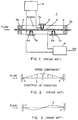
- FIG. 1 shows the configuration of the conventional straight-pipe mass flowmeter.
- a detecting unit 1 comprises a straight measurement pipe 2; right and left fixtures 3a and 3b for fixing the vibrating sections a and b of the measurement pipe 2; supporters 4a and 4b (only 4a is shown in FIG. 1) fixed to the fixtures 3a and 3b with screws or by soldering, etc., or designed as being combined with the fixtures 3a and 3b so that the vibrations of the fixtures 3a and 3b cancel each other; and a vibration generator 5, comprising coils fixed to the supporters 4a and 4b with an adapter 7a and a magnet fixed at the central portion of the measurement pipe 2, for vibrating of the measurement pipe 2 at its resonant frequency.
- the detecting unit 1 further comprises, similar to the vibration generator 5, speed detecting sensors (or displacement sensors or acceleration sensors) 6a and 6b, comprising magnets fixed symmetrically to the vibration generator 5 on the measurement pipe 2, with the coils fixed to the supporters 4a and 4b with the adapters 7b and 7c, for detecting the vibration of the measurement pipe 2; a drive circuit 8 for receiving an output from the speed detecting sensor 6a and outputting a drive signal to the vibration generator 5 so that the signal amplitude can be kept constant; and a signal processing circuit 9 for outputting a mass flow signal Qm based on the phase difference (time difference) of the signal from the speed detecting sensors 6a and 6b.
- speed detecting sensors or displacement sensors or acceleration sensors
- the measurement pipe 2 is vibrated at the resonant frequency of the vibration generator 5 and drive circuit 8. Since the speed detecting sensors 6a and 6b are mounted symmetrically about the center of the measurement pipe 2, signals of equal amplitude can be obtained without phase difference from the speed detecting sensors 6a and 6b.
- the speed component in the vibration direction is increased as shown in FIG. 2, as the fluid flows from the section a of the measurement pipe 2 toward the center of the measurement pipe 2. Therefore, the fluid flowing through the measurement pipe 2 receives positive acceleration from the measurement pipe 2 in the vibration direction. As a result, the reaction of the fluid is passed to the measurement pipe 2, and the phase of the vibration is delayed at the section a of the measurement pipe 2 toward the center of the measurement pipe 2, as shown in FIG. 3. Since the speed component in the vibration direction is decreased as the fluid flows from the center of the measurement pipe 2 to the section b, the fluid flowing through the measurement pipe 2 receives negative acceleration from the measurement pipe 2 in the vibration direction. As a result, the reaction of the fluid is passed to the measurement pipe 2, and the phase of the vibration is advanced at the center of the measurement pipe 2 toward the section b of the measurement pipe 2 as shown in FIG. 5.
- the displacement of the displacement sensor 6a is represented by the following equation, according to the displacement of the horizontal vibration of the measurement pipe 2 through resonance.
- Ya ⁇ (a) sin ⁇ n t
- the actual deformation of the measurement pipe 2 is determined by superimposing the deformation of the measurement pipe 2 as calculated by equation (2) onto the deformation of the measurement pipe 2 caused through the resonance calculated by equation (1). That is, the entire deformation of the measurement pipe 2 is calculated by combining equations (1) and (2) into equation (3).
- A [ ⁇ (a) 2 + ⁇ 2L 3 Qm ⁇ n ⁇ c (a) / EI ⁇ 2 ] 1/2
- ⁇ 2L 3 Qm ⁇ n ⁇ c (a) / EI ⁇ (a) Since the displacement sensors 6a and 6b are mounted symmetrically about the center of the measurement pipe 2, the displacement of the horizontal vibration of the measurement pipe 2 in the displacement sensor 6b is equal to the displacement of the displacement sensor 6a.
- the time difference between the signals of the displacement sensors 6a and 6b is calculated by the following equation (9).
- the resonant frequency of the measurement pipe 2 is calculated by the following equation (10).
- ⁇ n ⁇ 2 / L 2 ⁇ (EI / ⁇ ) 1/2
- the axial force (stress) working on the measurement pipe 2 has not been considered.
- the mass flowmeter measures the mass flow based on the Coriolis force generated by the mass flow of the fluid through the vibrating measurement pipe 2. If the temperature of the measurement pipe 2 changes with a variation in the temperature of the object fluid or the atmospheric temperature, the rigidity of the measurement pipe 2 changes with the temperature-dependency of Young's modulus for the measurement pipe 2, thereby changing the sensitivity to the Coriolis force and the measured flow value. If a Coriolis-type mass flowmeter having a straight measurement pipe is used, the axial force working on the measurement pipe changes with the expansion or contraction of the measurement pipe 2 and supporters 4a and 4b, because of the above described change in temperature. A change in the axial force also changes the sensitivity of the mass flow measurement.
- the resonant frequency changes with the temperature-dependency of Young's modulus for the measurement pipe 2, thereby generating erroneous measurements.
- the resonant frequency changes with the variation of the axial force working on the measurement pipe 2, generating erroneous measurements.
- two temperature sensors are mounted on the supporters 4a and 4b, and the portion indicating a temperature identical to that of the measurement pipe 2.
- the signals from the two temperature sensors are input to a correction circuit, and the flow signals from the two vibration sensors are also input to the correction circuit to be suitably corrected.
- the measured flow value is corrected corresponding to the temperature of the measurement pipe 2.
- the system includes a temperature sensor for detecting the temperature of the measurement pipe 2, and a length change sensor (for example, a deformation gauge such as a strain gauge) for correcting a measured value depending on the length and stress of the measurement pipe 2, and each signal is input to a correction circuit.
- a temperature sensor for detecting the temperature of the measurement pipe 2
- a length change sensor for example, a deformation gauge such as a strain gauge
- the deformation of the measurement pipe 2 is measured as in the Tokukaihei-6-94501, it is directly measured. Therefore, this ensures accurate deformation correction, however, because it is necessary to fix a strain gage and the like directly to the measurement pipe 2, the vibration characteristics of the measurement pipe 2 may be badly affected, this produces a problem with the stability of measurement.
- a mass is mounted on each side of the measurement pipe 2, and a strain gauge is applied to the outer side of the mass. At this time, the volume of the mass must be large with respect to the measurement pipe 2, generating another problem that the mass flow meter becomes large and slow.
- the first object of the present invention is to improve the measurement precision of the vibration measuring instrument at a low cost and without a complicated construction.
- the second object of the present invention is to reduce (or remove) the influence of density changes of the fluid to be measured on the measurement precision of the vibration measuring instrument, and to accurately correct the change in the measured value resulting from a density change of the fluid to be measured and a change in the axial force on the measurement pipe.
- the resonant frequency of a measurement pipe alters with a variation of the axial force (stress) T.
- the difference with a change in the axial force of constant ⁇ n (T) determined by the boundary condition and vibration mode depends on each vibration mode. Therefore, the resonant frequency ratio of each vibration mode changes with a change in an axial force.
- the resonant frequency ratio between each mode changes linearly with a change in the axial force. This is effective for the resonant frequency ratio between optional modes.
- the axial force working on the measurement pipe can be obtained by measuring the resonant frequency between modes.
- the present invention enables an accurate measurement to be realized by correcting the change in flow measurement sensitivity with the change in axial force working on the measurement pipe, corresponding to the resonant frequency ratio. Similarly, a measured density value is corrected based on the resonant frequency ratio.
- the influence of a density change on the resonant frequency can be reduced by mounting each adjustment mass to the mounting position of the mass of the vibration generator or vibration sensor, or the vibration sensor on the measurement pipe, and the position symmetrical with the mounting position of the vibration generator or vibration sensor on the measurement pipe.
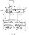
- a detecting unit 1 comprises a straight measurement pipe 2; right and left fixtures 3a and 3b for fixing the vibrating sections a and b of the measurement pipe 2; supporters 4a and 4b (only 4a is shown in FIG. 4) fixed to the fixtures 3a and 3b with screws or by soldering, etc., or designed as being combined with the fixtures 3a and 3b so that the vibrations of the fixtures 3a and 3b cancel each other; and a vibration generator 5, comprising coils fixed to the supporters 4a and 4b with an adapter 7a and a magnet fixed at the central portion of the measurement pipe 2, for vibrating the measurement pipe 2 at its resonant frequency.
- the detecting unit 1 further comprises, as the vibration generator 5, speed detecting sensors (or displacement sensors or acceleration sensors) 6a and 6b, comprising magnets fixed symmetrically to the vibration generator 5 on the measurement pipe 2, with the coils fixed to the supporters 4a and 4b with the adapters 7b and 7c, for detecting the vibration of the measurement pipe 2.
- speed detecting sensors or displacement sensors or acceleration sensors
- the characteristics of the first embodiment are a temperature sensor 10 added to the detecting unit 1; and a frequency ratio calculating unit 91, temperature calculating unit 93, and correction calculating unit 94 added to a signal processing circuit 9.
- Other features are the same as the construction shown in FIG. 1. Therefore, the explanation below concentrates on the differences between the present invention and the prior art.
- the phase or time difference of the output signal from the speed sensors 6a and 6b generated in proportion to the mass flow is a function of Young's modulus E and axial force T. Therefore, the output of the temperature sensor 10 is converted into a temperature signal by the temperature calculating unit 93. Then, the output of the speed sensor 6a, that is, the resonant frequency, is input to the frequency ratio calculating unit 91, and the resonant frequency is input to the frequency ratio calculating unit 91, and the resonant frequency ratio, which depends on the configuration of the detecting unit 1 and the current driving condition, is calculated.
- the correction calculating unit 94 receives the outputs from the frequency ratio calculating unit 91, phase difference calculating unit 92, temperature calculating unit 93, and speed sensor 6a.
- the phase difference signal from the phase difference calculating unit 92 is corrected by the resonant frequency of the measurement pipe obtained by the speed sensor 6a, and is converted into a time difference signal.
- the correction calculating unit 94 corrects the time difference signal according to the temperature signal from the temperature calculating unit 93, and the sensitivity correction signal which alters with a change in the axial force according to the resonant frequency ratio signal from the frequency ratio calculating unit 91.
- the ratio of the resonant frequency between the first and second vibration modes is obtained, and the measured value is corrected based on these resonant frequency ratios.
- the output from the speed sensor 6a is input for the correction calculating unit 94.
- the output from the speed sensor 6b can also be input to the correction calculating unit 94.
- a measured density value of the density meter can be corrected depending on the temperature and resonant frequency ratio.
- the measurement pipe has been described as having a uniform section.
- a measurement pipe 2 is directly provided with a vibration generator 5 for vibrating the measurement pipe 2, which is an added mass to the measurement pipe, and first and second speed detecting sensors 6a and 6b for detecting the vibration of the measurement pipe 2.
- the frequency ratio between optional two modes indicates a function of only an axial force T. If the measurement pipe has the above described added mass, it should be taken into account that the frequency ratio alters with the variation of the density of the measured fluid flowing through the measurement pipe.
- FIG. 6 shows the configuration showing the second embodiment of the present invention, taking into account the problem of the density-dependent frequency ratio.
- the detecting unit 1 is equipped with the magnet of the vibration generator 5 and an adjustment mass 11 for use in adjusting the mass of the fixture so that the resonant frequency ratio between the first and second vibration modes of the straight measurement pipe 2 can be independent of the influence of a change in the fluid density in the measurement pipe 2.
- Other features are the same as those of the configuration shown in FIG. 4 and accordingly the detailed explanation is omitted here.
- FIG. 7 shows an example of the relationship between the calculated value using the above listed equation (17) and the actual value (solid lines indicate the calculated value and broken lines indicate the actual value) of the density dependency of the resonant frequency ratio with the mass (g) of the vibration generator 5 changed. It indicates that the density dependency of the resonant frequency ratio alters with the function of the mass of the vibration generator 5, that is the mass of the vibration generator 5. Therefore, as with the above described embodiment, adjusting the mass of the vibration generator 5 reduces or finally removes the influence of a change in density on the resonant frequency ratio.
- FIG. 8 shows the calculation result of the density dependency of the ratio of the basic mode resonant frequency and the third mode resonant frequency to the position of the speed sensors 6a and 6b with the fluid density in a sample measurement pipe 2 changed.
- the positions of the speed sensors 6a and 6b are represented by the distance between the fixtures 3a and 3b as a percentage of the length of the measurement pipe 2.
- the density dependency of the resonant frequency ratio also changes with the mounting positions of the speed sensors 6a and 6b. Therefore, adjusting the positions of the speed sensors 6a and 6b reduces or finally removes the influence of a change in the fluid density in the measurement pipe 2 on the resonant frequency ratio.
- FIG. 9 shows the configuration according to the third embodiment of the present invention.
- the speed sensors 6a and 6b are mounted symmetrically about the vibration generator 5 on the measurement pipe 2 at the positions x from the fixtures 3a and 3b respectively.
- the distance x refers to a value at which the resonant frequency ratios of the first and second vibration modes of the measurement pipe 2 are not influenced by a change in the density of the fluid in the measurement pipe 2.
- FIG. 10 shows the fourth embodiment in which adjustment masses 12a and 12b are provided to adjust the masses of the magnets of the speed sensors 6a and 6b and the masses of the fixtures.
- This configuration can also reduce the influence of a change in the density of the fluid in the measurement pipe 2 on the resonant frequency ratios of the optional two vibration modes.
- the fifth embodiment shown in FIG. 11 comprises an adjustment mass 13 provided at a predetermined position on the measurement pipe 2, to enable the adjustment mass 13 to counter-balance the vibration generator 5.
- the sixth embodiment shown in FIG. 12 comprises adjustment masses 14a and 14b provided at predetermined positions on the measurement pipe 2, to enable the adjustment masses 14a and 14b to counter-balance the speed sensors 6a and 6b.
- adjusting the masses of the vibration generator 5 and speed sensors 6a and 6b, or adjusting the mounting positions of the vibration generator 5, speed sensors 6a and 6b, and additional masses 13, 14a, and 14b on the measurement pipe reduces the influence of a change in the density of the fluid in the measurement pipe 2 on the resonant frequency of the optional two vibration modes.
- adjusting the masses of the vibration generator 5 on the measurement pipe 2, and the speed sensors 6a and 6b or the positions of the speed sensors 6a and 6b on the measurement pipe 2 easily reduces the influence of a change in the density of the fluid in the measurement pipe 2 on the resonant frequency ratio of the first and second vibration modes.
- mounting the adjustment masses 13, 14a, and 14b to counter-balance the vibration generator 5 and speed sensors 6a and 6b reduces the influence of the position of the detecting unit 1.
Landscapes
- Physics & Mathematics (AREA)
- General Physics & Mathematics (AREA)
- Fluid Mechanics (AREA)
- General Health & Medical Sciences (AREA)
- Analytical Chemistry (AREA)
- Biochemistry (AREA)
- Chemical & Material Sciences (AREA)
- Life Sciences & Earth Sciences (AREA)
- Immunology (AREA)
- Pathology (AREA)
- Engineering & Computer Science (AREA)
- Signal Processing (AREA)
- Health & Medical Sciences (AREA)
- Measuring Volume Flow (AREA)
Applications Claiming Priority (6)
| Application Number | Priority Date | Filing Date | Title |
|---|---|---|---|
| JP21566394 | 1994-09-09 | ||
| JP21566394A JPH0875521A (ja) | 1994-09-09 | 1994-09-09 | 振動型測定器 |
| JP215663/94 | 1994-09-09 | ||
| JP01758895A JP3262193B2 (ja) | 1995-02-06 | 1995-02-06 | 振動型測定器 |
| JP1758895 | 1995-02-06 | ||
| JP17588/95 | 1995-02-06 |
Publications (3)
| Publication Number | Publication Date |
|---|---|
| EP0701107A2 true EP0701107A2 (fr) | 1996-03-13 |
| EP0701107A3 EP0701107A3 (fr) | 1996-12-11 |
| EP0701107B1 EP0701107B1 (fr) | 2000-03-15 |
Family
ID=26354143
Family Applications (1)
| Application Number | Title | Priority Date | Filing Date |
|---|---|---|---|
| EP95114040A Expired - Lifetime EP0701107B1 (fr) | 1994-09-09 | 1995-09-07 | Instrument pour la mesure d'une vibration |
Country Status (3)
| Country | Link |
|---|---|
| US (1) | US5728952A (fr) |
| EP (1) | EP0701107B1 (fr) |
| DE (1) | DE69515576T2 (fr) |
Cited By (20)
| Publication number | Priority date | Publication date | Assignee | Title |
|---|---|---|---|---|
| WO1997040348A1 (fr) * | 1996-04-22 | 1997-10-30 | Direct Measurement Corporation | Appareils et procedes de traitement des signaux visant a attenuer les decalages de l'interception du zero pouvant etre attribues au changement d'une condition limite d'un debitmetre massique de coriolis |
| WO1998031990A1 (fr) * | 1997-01-16 | 1998-07-23 | Direct Measurement Corporation | Procedes de traitement de signaux et de verification sur place, et circuits pour debitmetre-masse a acceleration de coriolis |
| US6092429A (en) * | 1997-12-04 | 2000-07-25 | Micro Motion, Inc. | Driver for oscillating a vibrating conduit |
| GB2350426A (en) * | 1999-05-25 | 2000-11-29 | Abb Instrumentation Ltd | Vibrating tube meter |
| US6199022B1 (en) | 1997-07-11 | 2001-03-06 | Micro Motion, Inc. | Drive circuit modal filter for a vibrating tube flowmeter |
| US6227059B1 (en) | 1999-01-12 | 2001-05-08 | Direct Measurement Corporation | System and method for employing an imaginary difference signal component to compensate for boundary condition effects on a Coriolis mass flow meter |
| US6233526B1 (en) | 1998-07-16 | 2001-05-15 | Micro Motion, Inc. | Vibrating conduit parameter sensors and methods of operation therefor utilizing spatial integration |
| US6249752B1 (en) | 1998-07-16 | 2001-06-19 | Micro Motion, Inc. | Vibrating conduit parameter sensors, operating methods and computer program productors utilizing real normal modal decomposition |
| US6360175B1 (en) | 1998-02-25 | 2002-03-19 | Micro Motion, Inc. | Generalized modal space drive control system for a vibrating tube process parameter sensor |
| US6427127B1 (en) | 1998-07-16 | 2002-07-30 | Micro Motion, Inc. | Vibrating conduit process parameter sensors, operating methods and computer program products utilizing complex modal estimation |
| US6513393B1 (en) | 1998-12-11 | 2003-02-04 | Flowtec Ag | Coriolis mass/flow density meter |
| US6577977B2 (en) | 1999-02-16 | 2003-06-10 | Micro Motion, Inc. | Process parameter sensor apparatus, methods and computer program products using force filtering |
| EP1109016A3 (fr) * | 1999-12-16 | 2005-03-30 | Halliburton Energy Services, Inc. | Moniteur de propriétés de fluides |
| WO2006041427A1 (fr) * | 2004-09-17 | 2006-04-20 | Emerson Electric Co. | Procede et dispositif de compensation pour debitmetre a effet coriolis |
| RU2344376C1 (ru) * | 2004-09-17 | 2009-01-20 | Эмерсон Электрик Ко. | Способ и устройство компенсации для кориолисова расходомера |
| WO2009051588A1 (fr) * | 2007-10-15 | 2009-04-23 | Micro Motion, Inc. | Débitmètre vibrant et procédé permettant de déterminer une température de fluide d'une substance en écoulement |
| CN102052944A (zh) * | 2009-11-10 | 2011-05-11 | 横河电机株式会社 | 科里奥利质量流量计 |
| EP1989517A4 (fr) * | 2006-02-13 | 2011-11-23 | Invensys Sys Inc | Compensation de changement de frequence dans des debitmetres |
| RU2443980C2 (ru) * | 2007-10-15 | 2012-02-27 | Майкро Моушн, Инк. | Вибрационный расходомер и способ определения температуры жидкости текущего материала |
| CN110114642A (zh) * | 2016-12-29 | 2019-08-09 | 恩德斯+豪斯流量技术股份有限公司 | 用于测量质量流率的电子振动测量系统 |
Families Citing this family (18)
| Publication number | Priority date | Publication date | Assignee | Title |
|---|---|---|---|---|
| US6513392B1 (en) | 1998-12-08 | 2003-02-04 | Emerson Electric Co. | Coriolis mass flow controller |
| US6748813B1 (en) | 1998-12-08 | 2004-06-15 | Emerson Electric Company | Coriolis mass flow controller |
| US6502466B1 (en) * | 1999-06-29 | 2003-01-07 | Direct Measurement Corporation | System and method for fluid compressibility compensation in a Coriolis mass flow meter |
| US6694279B2 (en) | 2001-02-16 | 2004-02-17 | Micro Motion, Inc. | Methods, apparatus, and computer program products for determining structural motion using mode selective filtering |
| US6535826B2 (en) | 2001-02-16 | 2003-03-18 | Micro Motion, Inc. | Mass flowmeter methods, apparatus, and computer program products using correlation-measure-based status determination |
| US6466880B2 (en) | 2001-02-16 | 2002-10-15 | Micro Motion, Inc. | Mass flow measurement methods, apparatus, and computer program products using mode selective filtering |
| DE102004056235A1 (de) * | 2004-10-29 | 2006-05-04 | Krohne Ag | Verfahren zum Betreiben eines Massendurchflußmeßgeräts |
| DE102009028006A1 (de) | 2009-07-24 | 2011-01-27 | Endress + Hauser Flowtec Ag | Meßwandler vom Vibrationstyp sowie Meßgerät mit einem solchen Meßwandler |
| US9752911B2 (en) | 2014-12-29 | 2017-09-05 | Concentric Meter Corporation | Fluid parameter sensor and meter |
| US10107784B2 (en) | 2014-12-29 | 2018-10-23 | Concentric Meter Corporation | Electromagnetic transducer |
| US10126266B2 (en) | 2014-12-29 | 2018-11-13 | Concentric Meter Corporation | Fluid parameter sensor and meter |
| DE102015112737A1 (de) * | 2015-08-03 | 2017-02-09 | Endress + Hauser Flowtec Ag | Verfahren zum Ermitteln eines physikalischen Parameters eines Gases |
| US9719826B2 (en) * | 2015-08-12 | 2017-08-01 | Honeywell International Inc. | Mass flow primary with exciter |
| EA035603B1 (ru) * | 2017-12-14 | 2020-07-15 | Ерлан Жандарбекович Джунусбеков | Устройство и виброгенератор для подавления акустических шумов |
| EP4168752B1 (fr) | 2020-06-18 | 2025-08-13 | Endress+Hauser Flowtec AG | Système de mesure vibronique |
| DE102020131649A1 (de) | 2020-09-03 | 2022-03-03 | Endress + Hauser Flowtec Ag | Vibronisches Meßsystem |
| DE102020127382A1 (de) | 2020-10-16 | 2022-04-21 | Endress+Hauser Flowtec Ag | Verfahren zum Überprüfen eines vibronischen Meßsystems |
| JP7507446B1 (ja) * | 2022-11-04 | 2024-06-28 | 株式会社AlphiTechnology | コリオリ質量流量計 |
Citations (2)
| Publication number | Priority date | Publication date | Assignee | Title |
|---|---|---|---|---|
| JPH0569452A (ja) | 1991-09-12 | 1993-03-23 | Daihatsu Motor Co Ltd | 自動車用樹脂製バンパの製造法 |
| JPH0694501A (ja) | 1992-07-06 | 1994-04-05 | Krohne Messtech Gmbh & Co Kg | 質量流量測定装置 |
Family Cites Families (17)
| Publication number | Priority date | Publication date | Assignee | Title |
|---|---|---|---|---|
| US4823614A (en) * | 1986-04-28 | 1989-04-25 | Dahlin Erik B | Coriolis-type mass flowmeter |
| AU590995B2 (en) * | 1986-10-03 | 1989-11-23 | Micro Motion, Inc. | Density insensitive coriolis mass flow rate meter |
| WO1988002853A1 (fr) * | 1986-10-09 | 1988-04-21 | Micro Motion, Inc. | Appareil et procedes de mesure de la densite d'un fluide inconnu en utilisant un debitmetre de coriolis |
| ATE85116T1 (de) * | 1987-07-15 | 1993-02-15 | Micro Motion Inc | Massendurchflussmesser mit einer kompensation der asymmetrie und einer zaehfluessigen daempfung. |
| DE3829062A1 (de) * | 1988-08-26 | 1990-03-08 | Danfoss As | Nach dem coriolis-prinzip arbeitendes stroemungsmessgeraet (iv) |
| US5115683A (en) * | 1988-09-27 | 1992-05-26 | K-Flow Division Of Kane Steel Co., Inc. | Coriolis mass flow meter adapted for low flow rates |
| DE3923409A1 (de) * | 1989-07-14 | 1991-01-24 | Danfoss As | Nach dem coriolis-prinzip arbeitendes massendurchfluss-messgeraet |
| US5054326A (en) * | 1990-03-05 | 1991-10-08 | The Foxboro Company | Density compensator for coriolis-type mass flowmeters |
| US5448921A (en) * | 1991-02-05 | 1995-09-12 | Direct Measurement Corporation | Coriolis mass flow rate meter |
| US5373745A (en) * | 1991-02-05 | 1994-12-20 | Direct Measurement Corporation | Single path radial mode Coriolis mass flow rate meter |
| JP3056553B2 (ja) * | 1991-09-17 | 2000-06-26 | 大建工業株式会社 | 無機質化粧板の製造方法 |
| JPH0663958A (ja) * | 1992-08-12 | 1994-03-08 | F Tec:Kk | 通気性成形用金型の製造方法 |
| JP2758798B2 (ja) * | 1992-11-19 | 1998-05-28 | 株式会社オーバル | コリオリ流量計 |
| JP3219122B2 (ja) * | 1994-07-11 | 2001-10-15 | 横河電機株式会社 | コリオリ質量流量計 |
| US5469748A (en) * | 1994-07-20 | 1995-11-28 | Micro Motion, Inc. | Noise reduction filter system for a coriolis flowmeter |
| EP0698783A1 (fr) * | 1994-08-16 | 1996-02-28 | Endress + Hauser Flowtec AG | Circuit d'évaluation d'un capteur de débitmètre selon le principe de coriolis |
| JP3058074B2 (ja) * | 1995-08-29 | 2000-07-04 | 富士電機株式会社 | 振動型測定器 |
-
1995
- 1995-09-07 EP EP95114040A patent/EP0701107B1/fr not_active Expired - Lifetime
- 1995-09-07 DE DE69515576T patent/DE69515576T2/de not_active Expired - Lifetime
- 1995-09-08 US US08/525,466 patent/US5728952A/en not_active Expired - Lifetime
Patent Citations (2)
| Publication number | Priority date | Publication date | Assignee | Title |
|---|---|---|---|---|
| JPH0569452A (ja) | 1991-09-12 | 1993-03-23 | Daihatsu Motor Co Ltd | 自動車用樹脂製バンパの製造法 |
| JPH0694501A (ja) | 1992-07-06 | 1994-04-05 | Krohne Messtech Gmbh & Co Kg | 質量流量測定装置 |
Cited By (35)
| Publication number | Priority date | Publication date | Assignee | Title |
|---|---|---|---|---|
| US5827979A (en) * | 1996-04-22 | 1998-10-27 | Direct Measurement Corporation | Signal processing apparati and methods for attenuating shifts in zero intercept attributable to a changing boundary condition in a Coriolis mass flow meter |
| WO1997040348A1 (fr) * | 1996-04-22 | 1997-10-30 | Direct Measurement Corporation | Appareils et procedes de traitement des signaux visant a attenuer les decalages de l'interception du zero pouvant etre attribues au changement d'une condition limite d'un debitmetre massique de coriolis |
| WO1998031990A1 (fr) * | 1997-01-16 | 1998-07-23 | Direct Measurement Corporation | Procedes de traitement de signaux et de verification sur place, et circuits pour debitmetre-masse a acceleration de coriolis |
| US6199022B1 (en) | 1997-07-11 | 2001-03-06 | Micro Motion, Inc. | Drive circuit modal filter for a vibrating tube flowmeter |
| US6092429A (en) * | 1997-12-04 | 2000-07-25 | Micro Motion, Inc. | Driver for oscillating a vibrating conduit |
| US6360175B1 (en) | 1998-02-25 | 2002-03-19 | Micro Motion, Inc. | Generalized modal space drive control system for a vibrating tube process parameter sensor |
| US6427127B1 (en) | 1998-07-16 | 2002-07-30 | Micro Motion, Inc. | Vibrating conduit process parameter sensors, operating methods and computer program products utilizing complex modal estimation |
| US6233526B1 (en) | 1998-07-16 | 2001-05-15 | Micro Motion, Inc. | Vibrating conduit parameter sensors and methods of operation therefor utilizing spatial integration |
| US6249752B1 (en) | 1998-07-16 | 2001-06-19 | Micro Motion, Inc. | Vibrating conduit parameter sensors, operating methods and computer program productors utilizing real normal modal decomposition |
| US6513393B1 (en) | 1998-12-11 | 2003-02-04 | Flowtec Ag | Coriolis mass/flow density meter |
| US6227059B1 (en) | 1999-01-12 | 2001-05-08 | Direct Measurement Corporation | System and method for employing an imaginary difference signal component to compensate for boundary condition effects on a Coriolis mass flow meter |
| US6577977B2 (en) | 1999-02-16 | 2003-06-10 | Micro Motion, Inc. | Process parameter sensor apparatus, methods and computer program products using force filtering |
| GB2350426B (en) * | 1999-05-25 | 2002-08-28 | Abb Instrumentation Ltd | Vibrating tube meter |
| GB2350426A (en) * | 1999-05-25 | 2000-11-29 | Abb Instrumentation Ltd | Vibrating tube meter |
| US6763730B1 (en) | 1999-05-25 | 2004-07-20 | Abb Limited | Vibrating tube meter |
| EP1109016A3 (fr) * | 1999-12-16 | 2005-03-30 | Halliburton Energy Services, Inc. | Moniteur de propriétés de fluides |
| WO2006041427A1 (fr) * | 2004-09-17 | 2006-04-20 | Emerson Electric Co. | Procede et dispositif de compensation pour debitmetre a effet coriolis |
| US7628084B2 (en) | 2004-09-17 | 2009-12-08 | Emerson Electric Co. | Compensation method and apparatus for a coriolis flow meter |
| AU2004324097B2 (en) * | 2004-09-17 | 2010-01-21 | Emerson Electric Co. | Compensation method and apparatus for a coriolis flow meter |
| RU2344376C1 (ru) * | 2004-09-17 | 2009-01-20 | Эмерсон Электрик Ко. | Способ и устройство компенсации для кориолисова расходомера |
| EP1989517A4 (fr) * | 2006-02-13 | 2011-11-23 | Invensys Sys Inc | Compensation de changement de frequence dans des debitmetres |
| US8706430B2 (en) | 2006-02-13 | 2014-04-22 | Invensys Systems, Inc. | Compensating for frequency change in flowmeters |
| US8473224B2 (en) | 2006-02-13 | 2013-06-25 | Invensys Systems, Inc. | Compensating for frequency change in flowmeters |
| RU2443980C2 (ru) * | 2007-10-15 | 2012-02-27 | Майкро Моушн, Инк. | Вибрационный расходомер и способ определения температуры жидкости текущего материала |
| AU2007360170B2 (en) * | 2007-10-15 | 2011-09-08 | Micro Motion, Inc. | Vibratory flow meter and method for determining a fluid temperature of a flow material |
| US8302491B2 (en) | 2007-10-15 | 2012-11-06 | Micro Motion, Inc. | Vibratory flow meter and method for determining a fluid temperature of a flow material |
| WO2009051588A1 (fr) * | 2007-10-15 | 2009-04-23 | Micro Motion, Inc. | Débitmètre vibrant et procédé permettant de déterminer une température de fluide d'une substance en écoulement |
| CN101821593B (zh) * | 2007-10-15 | 2016-02-03 | 微动公司 | 用于确定流动材料的流体温度的振动式流量计和方法 |
| EP2410300A1 (fr) * | 2009-11-10 | 2012-01-25 | Yokogawa Electric Corporation | Débitmètre de masse Coriolis |
| CN102052944B (zh) * | 2009-11-10 | 2013-01-16 | 横河电机株式会社 | 科里奥利质量流量计 |
| US8374805B2 (en) | 2009-11-10 | 2013-02-12 | Yokogawa Electric Corporation | Coriolis mass flowmeter |
| CN102052944A (zh) * | 2009-11-10 | 2011-05-11 | 横河电机株式会社 | 科里奥利质量流量计 |
| CN110114642A (zh) * | 2016-12-29 | 2019-08-09 | 恩德斯+豪斯流量技术股份有限公司 | 用于测量质量流率的电子振动测量系统 |
| US10928233B2 (en) | 2016-12-29 | 2021-02-23 | Endress+Hauser Flowtec Ag | Vibronic measuring system for measuring a mass flow rate |
| CN110114642B (zh) * | 2016-12-29 | 2021-06-08 | 恩德斯+豪斯流量技术股份有限公司 | 用于测量质量流率的电子振动测量系统 |
Also Published As
| Publication number | Publication date |
|---|---|
| EP0701107A3 (fr) | 1996-12-11 |
| DE69515576D1 (de) | 2000-04-20 |
| DE69515576T2 (de) | 2000-09-14 |
| EP0701107B1 (fr) | 2000-03-15 |
| US5728952A (en) | 1998-03-17 |
Similar Documents
| Publication | Publication Date | Title |
|---|---|---|
| EP0701107B1 (fr) | Instrument pour la mesure d'une vibration | |
| US5831178A (en) | Vibration type measuring instrument | |
| EP0161049B1 (fr) | Capteur de vitesse angulaire | |
| US5069075A (en) | Mass flow meter working on the coriolis principle | |
| KR100436483B1 (ko) | 코리올리 유량계용 계기 전자부품, 및 그것에 의해 사용되는 흐름 교정 계수를 검증하는 방법 | |
| RU2320964C2 (ru) | Прибор для измерения физических параметров | |
| JP3565588B2 (ja) | 振動型測定器 | |
| AU717965B2 (en) | Vibration type measuring instrument | |
| GB2350426A (en) | Vibrating tube meter | |
| US5773727A (en) | Mass flow meter | |
| CN104813147A (zh) | 对振动计中流体管的截面面积的改变的改进检测 | |
| EP3129755B1 (fr) | Débitmètre vibrant amélioré et procédés associés | |
| US12215992B2 (en) | Apparatus for applying a temperature flow coefficient in a vibrating flowmeter and related method | |
| JP2966356B2 (ja) | 質量流量計変換器 | |
| JP3058094B2 (ja) | 質量流量計 | |
| JP2976765B2 (ja) | コリオリ質量流量計 | |
| JPH0875521A (ja) | 振動型測定器 | |
| US20260049854A1 (en) | Mode excitation detection for a vibratory flowmeter and related methods | |
| JPH1090034A (ja) | コリオリ流量計 | |
| JPH0783721A (ja) | 振動式測定装置 | |
| JP3262193B2 (ja) | 振動型測定器 | |
| JPH08193864A (ja) | コリオリ質量流量計 | |
| JPH0712612A (ja) | コリオリ式質量流量計 | |
| JPH07286879A (ja) | コリオリ質量流量計 | |
| JPH06147948A (ja) | コリオリ質量流量計 |
Legal Events
| Date | Code | Title | Description |
|---|---|---|---|
| PUAI | Public reference made under article 153(3) epc to a published international application that has entered the european phase |
Free format text: ORIGINAL CODE: 0009012 |
|
| AK | Designated contracting states |
Kind code of ref document: A2 Designated state(s): CH DE FR GB IT LI |
|
| PUAL | Search report despatched |
Free format text: ORIGINAL CODE: 0009013 |
|
| RHK1 | Main classification (correction) |
Ipc: G01F 1/84 |
|
| AK | Designated contracting states |
Kind code of ref document: A3 Designated state(s): CH DE FR GB IT LI |
|
| 17P | Request for examination filed |
Effective date: 19970605 |
|
| 17Q | First examination report despatched |
Effective date: 19980513 |
|
| GRAG | Despatch of communication of intention to grant |
Free format text: ORIGINAL CODE: EPIDOS AGRA |
|
| GRAG | Despatch of communication of intention to grant |
Free format text: ORIGINAL CODE: EPIDOS AGRA |
|
| GRAH | Despatch of communication of intention to grant a patent |
Free format text: ORIGINAL CODE: EPIDOS IGRA |
|
| GRAH | Despatch of communication of intention to grant a patent |
Free format text: ORIGINAL CODE: EPIDOS IGRA |
|
| GRAA | (expected) grant |
Free format text: ORIGINAL CODE: 0009210 |
|
| AK | Designated contracting states |
Kind code of ref document: B1 Designated state(s): CH DE FR GB IT LI |
|
| REG | Reference to a national code |
Ref country code: CH Ref legal event code: EP |
|
| REF | Corresponds to: |
Ref document number: 69515576 Country of ref document: DE Date of ref document: 20000420 |
|
| ITF | It: translation for a ep patent filed | ||
| REG | Reference to a national code |
Ref country code: CH Ref legal event code: NV Representative=s name: KIRKER & CIE SA |
|
| ET | Fr: translation filed | ||
| PLBE | No opposition filed within time limit |
Free format text: ORIGINAL CODE: 0009261 |
|
| STAA | Information on the status of an ep patent application or granted ep patent |
Free format text: STATUS: NO OPPOSITION FILED WITHIN TIME LIMIT |
|
| 26N | No opposition filed | ||
| REG | Reference to a national code |
Ref country code: GB Ref legal event code: IF02 |
|
| REG | Reference to a national code |
Ref country code: CH Ref legal event code: PUE Owner name: ENDRESS + HAUSER FLOWTEC AG Free format text: FUJI ELECTRIC CO. LTD.#1-1, TANABESHINDEN, KAWASAKI-KU#KAWASAKI 210 (JP) TRANSFER- ENDRESS + HAUSER FLOWTEC AG#KAEGENSTRASSE 7#4153 REINACH BL (CH) Ref country code: CH Ref legal event code: NV Representative=s name: BOVARD AG PATENTANWAELTE |
|
| REG | Reference to a national code |
Ref country code: GB Ref legal event code: 732E |
|
| REG | Reference to a national code |
Ref country code: FR Ref legal event code: TP |
|
| REG | Reference to a national code |
Ref country code: CH Ref legal event code: PFA Owner name: ENDRESS + HAUSER FLOWTEC AG Free format text: ENDRESS + HAUSER FLOWTEC AG#KAEGENSTRASSE 7#4153 REINACH BL (CH) -TRANSFER TO- ENDRESS + HAUSER FLOWTEC AG#KAEGENSTRASSE 7#4153 REINACH BL (CH) |
|
| PGFP | Annual fee paid to national office [announced via postgrant information from national office to epo] |
Ref country code: CH Payment date: 20110923 Year of fee payment: 17 |
|
| PGFP | Annual fee paid to national office [announced via postgrant information from national office to epo] |
Ref country code: GB Payment date: 20120920 Year of fee payment: 18 |
|
| PGFP | Annual fee paid to national office [announced via postgrant information from national office to epo] |
Ref country code: FR Payment date: 20121010 Year of fee payment: 18 |
|
| PGFP | Annual fee paid to national office [announced via postgrant information from national office to epo] |
Ref country code: IT Payment date: 20120926 Year of fee payment: 18 |
|
| PGFP | Annual fee paid to national office [announced via postgrant information from national office to epo] |
Ref country code: DE Payment date: 20130919 Year of fee payment: 19 |
|
| REG | Reference to a national code |
Ref country code: CH Ref legal event code: PL |
|
| GBPC | Gb: european patent ceased through non-payment of renewal fee |
Effective date: 20130907 |
|
| REG | Reference to a national code |
Ref country code: FR Ref legal event code: ST Effective date: 20140530 |
|
| PG25 | Lapsed in a contracting state [announced via postgrant information from national office to epo] |
Ref country code: LI Free format text: LAPSE BECAUSE OF NON-PAYMENT OF DUE FEES Effective date: 20130930 Ref country code: GB Free format text: LAPSE BECAUSE OF NON-PAYMENT OF DUE FEES Effective date: 20130907 Ref country code: CH Free format text: LAPSE BECAUSE OF NON-PAYMENT OF DUE FEES Effective date: 20130930 |
|
| PG25 | Lapsed in a contracting state [announced via postgrant information from national office to epo] |
Ref country code: IT Free format text: LAPSE BECAUSE OF NON-PAYMENT OF DUE FEES Effective date: 20130907 Ref country code: FR Free format text: LAPSE BECAUSE OF NON-PAYMENT OF DUE FEES Effective date: 20130930 |
|
| REG | Reference to a national code |
Ref country code: DE Ref legal event code: R119 Ref document number: 69515576 Country of ref document: DE |
|
| PG25 | Lapsed in a contracting state [announced via postgrant information from national office to epo] |
Ref country code: DE Free format text: LAPSE BECAUSE OF NON-PAYMENT OF DUE FEES Effective date: 20150401 |