EP0701109A2 - Compteur d'eau - Google Patents
Compteur d'eau Download PDFInfo
- Publication number
- EP0701109A2 EP0701109A2 EP95112728A EP95112728A EP0701109A2 EP 0701109 A2 EP0701109 A2 EP 0701109A2 EP 95112728 A EP95112728 A EP 95112728A EP 95112728 A EP95112728 A EP 95112728A EP 0701109 A2 EP0701109 A2 EP 0701109A2
- Authority
- EP
- European Patent Office
- Prior art keywords
- water meter
- transmission
- meter according
- counting
- display device
- Prior art date
- Legal status (The legal status is an assumption and is not a legal conclusion. Google has not performed a legal analysis and makes no representation as to the accuracy of the status listed.)
- Withdrawn
Links
- 230000005540 biological transmission Effects 0.000 claims abstract description 32
- XLYOFNOQVPJJNP-UHFFFAOYSA-N water Substances O XLYOFNOQVPJJNP-UHFFFAOYSA-N 0.000 claims description 49
- 230000004888 barrier function Effects 0.000 claims description 18
- 238000005259 measurement Methods 0.000 claims description 6
- 238000001514 detection method Methods 0.000 claims description 4
- 230000000737 periodic effect Effects 0.000 claims description 4
- 235000014676 Phragmites communis Nutrition 0.000 claims description 2
- 239000003550 marker Substances 0.000 claims 1
- 125000004122 cyclic group Chemical group 0.000 abstract 1
- 230000010354 integration Effects 0.000 description 2
- 238000000034 method Methods 0.000 description 2
- 230000011514 reflex Effects 0.000 description 2
- 238000009420 retrofitting Methods 0.000 description 2
- 230000008878 coupling Effects 0.000 description 1
- 238000010168 coupling process Methods 0.000 description 1
- 238000005859 coupling reaction Methods 0.000 description 1
- 239000013078 crystal Substances 0.000 description 1
- 230000001419 dependent effect Effects 0.000 description 1
- 238000010586 diagram Methods 0.000 description 1
- 238000007654 immersion Methods 0.000 description 1
- 238000009434 installation Methods 0.000 description 1
- 238000004519 manufacturing process Methods 0.000 description 1
- 239000010453 quartz Substances 0.000 description 1
- VYPSYNLAJGMNEJ-UHFFFAOYSA-N silicon dioxide Inorganic materials O=[Si]=O VYPSYNLAJGMNEJ-UHFFFAOYSA-N 0.000 description 1
Images



Classifications
-
- G—PHYSICS
- G01—MEASURING; TESTING
- G01F—MEASURING VOLUME, VOLUME FLOW, MASS FLOW OR LIQUID LEVEL; METERING BY VOLUME
- G01F1/00—Measuring the volume flow or mass flow of fluid or fluent solid material wherein the fluid passes through a meter in a continuous flow
- G01F1/05—Measuring the volume flow or mass flow of fluid or fluent solid material wherein the fluid passes through a meter in a continuous flow by using mechanical effects
- G01F1/06—Measuring the volume flow or mass flow of fluid or fluent solid material wherein the fluid passes through a meter in a continuous flow by using mechanical effects using rotating vanes with tangential admission
- G01F1/075—Measuring the volume flow or mass flow of fluid or fluent solid material wherein the fluid passes through a meter in a continuous flow by using mechanical effects using rotating vanes with tangential admission with magnetic or electromagnetic coupling to the indicating device
- G01F1/0755—Measuring the volume flow or mass flow of fluid or fluent solid material wherein the fluid passes through a meter in a continuous flow by using mechanical effects using rotating vanes with tangential admission with magnetic or electromagnetic coupling to the indicating device with magnetic coupling only in a mechanical transmission path
-
- G—PHYSICS
- G01—MEASURING; TESTING
- G01D—MEASURING NOT SPECIALLY ADAPTED FOR A SPECIFIC VARIABLE; ARRANGEMENTS FOR MEASURING TWO OR MORE VARIABLES NOT COVERED IN A SINGLE OTHER SUBCLASS; TARIFF METERING APPARATUS; MEASURING OR TESTING NOT OTHERWISE PROVIDED FOR
- G01D4/00—Tariff metering apparatus
- G01D4/002—Remote reading of utility meters
- G01D4/004—Remote reading of utility meters to a fixed location
-
- G—PHYSICS
- G01—MEASURING; TESTING
- G01D—MEASURING NOT SPECIALLY ADAPTED FOR A SPECIFIC VARIABLE; ARRANGEMENTS FOR MEASURING TWO OR MORE VARIABLES NOT COVERED IN A SINGLE OTHER SUBCLASS; TARIFF METERING APPARATUS; MEASURING OR TESTING NOT OTHERWISE PROVIDED FOR
- G01D4/00—Tariff metering apparatus
- G01D4/02—Details
-
- G—PHYSICS
- G01—MEASURING; TESTING
- G01F—MEASURING VOLUME, VOLUME FLOW, MASS FLOW OR LIQUID LEVEL; METERING BY VOLUME
- G01F15/00—Details of, or accessories for, apparatus of groups G01F1/00 - G01F13/00 insofar as such details or appliances are not adapted to particular types of such apparatus
- G01F15/06—Indicating or recording devices
- G01F15/061—Indicating or recording devices for remote indication
- G01F15/063—Indicating or recording devices for remote indication using electrical means
-
- Y—GENERAL TAGGING OF NEW TECHNOLOGICAL DEVELOPMENTS; GENERAL TAGGING OF CROSS-SECTIONAL TECHNOLOGIES SPANNING OVER SEVERAL SECTIONS OF THE IPC; TECHNICAL SUBJECTS COVERED BY FORMER USPC CROSS-REFERENCE ART COLLECTIONS [XRACs] AND DIGESTS
- Y02—TECHNOLOGIES OR APPLICATIONS FOR MITIGATION OR ADAPTATION AGAINST CLIMATE CHANGE
- Y02B—CLIMATE CHANGE MITIGATION TECHNOLOGIES RELATED TO BUILDINGS, e.g. HOUSING, HOUSE APPLIANCES OR RELATED END-USER APPLICATIONS
- Y02B90/00—Enabling technologies or technologies with a potential or indirect contribution to GHG emissions mitigation
- Y02B90/20—Smart grids as enabling technology in buildings sector
-
- Y—GENERAL TAGGING OF NEW TECHNOLOGICAL DEVELOPMENTS; GENERAL TAGGING OF CROSS-SECTIONAL TECHNOLOGIES SPANNING OVER SEVERAL SECTIONS OF THE IPC; TECHNICAL SUBJECTS COVERED BY FORMER USPC CROSS-REFERENCE ART COLLECTIONS [XRACs] AND DIGESTS
- Y04—INFORMATION OR COMMUNICATION TECHNOLOGIES HAVING AN IMPACT ON OTHER TECHNOLOGY AREAS
- Y04S—SYSTEMS INTEGRATING TECHNOLOGIES RELATED TO POWER NETWORK OPERATION, COMMUNICATION OR INFORMATION TECHNOLOGIES FOR IMPROVING THE ELECTRICAL POWER GENERATION, TRANSMISSION, DISTRIBUTION, MANAGEMENT OR USAGE, i.e. SMART GRIDS
- Y04S20/00—Management or operation of end-user stationary applications or the last stages of power distribution; Controlling, monitoring or operating thereof
- Y04S20/30—Smart metering, e.g. specially adapted for remote reading
Definitions
- the invention relates to a water meter with a measuring device arranged in a first housing area, in particular an impeller, for volume or quantity measurement and a metering and / or display device arranged in a second housing area and interacting with the measuring device, the two housing areas being separated from one another in a sealed manner .
- the invention is therefore based on the object of creating a water meter to be installed in a household, which allows the utility company to read the meter reading safely and with as little effort as possible without entering the respective home of the end customer, and which can also be easily installed using the retrofitting method.
- a radio-technical transmitting device which interacts with the meter and is fed from an energy source, is provided for transmitting the meter reading to a central, remote receiving system.
- the water meter according to the invention thus sends the meter reading to a separate reception system, which is arranged, for example, centrally in the hallway, basement or the like of the house, for example a multi-storey apartment building, where the reader can easily read the meter reading without entering the respective apartments.
- the meter reading can be transmitted in a stochastic sequence or periodically several times a day. If, for example, the house is fully equipped with such water meters, all meters can be read simultaneously on the reception system without anyone having to be present.
- Another advantage of radio transmission which takes place during periodic operation, for example at predetermined time or quantity intervals, for example every hour or per hundred liters, is the reduction of the reading errors through automatically secured data transmission. Furthermore, there is no effort in shorter intervals, for. B. monthly, can be read, greater justice when changing tariffs or tenants. Since no additional elements to be installed in the apartment are required, the water meter can also be easily installed using the retrofit method.
- the transmission device in particular the transmission elements has a transmitting antenna and possibly the circuit board carrying the counting and / or display device, which is simply inserted into the upper, second housing area.
- the counter and / or display device of which is a mechanical device, preferably a roller counter according to the invention a sensor device with a sensor for detecting a marking, which is arranged on the mechanical metering device and indicates a certain counted volume or quantity or the like may be provided, the transmission of the radio signals possibly taking place as a function of the sensor detection.
- the sensor can be a micro switch that is optionally actuated by means of a separate shaft, preferably driven by a transmission gear, alternatively an opto switch or a reed switch can also be used.
- opto-switches which are designed as light barriers have proven to be extremely useful, preferably two such light barriers being connected in series.
- Each light barrier transmits a separate signal at a time when the marking is detected, so that in the event that water flows back through the counter, which results in a backward rotation of the counter and thus the marking, these are determined on the basis of the signals coming from the light barriers can.
- This is advantageous in that the respective counter value originating from the reverse rotation, which would falsify the measurement result, is not included in the calculation.
- a shaft which: drives the marking or a disk carrying the marking in rotation and which is coupled to the counter, the marking coming into operative connection with the sensor as part of the rotation.
- a second alternative embodiment of a water meter according to the invention which has an electronic counting and / or display device, in particular an LCD device, which comprises an electronic control element, preferably a microprocessor, which controls it and is powered by an energy source, is designed according to the invention such that the control device also includes is connected to the control element, the control element controlling the transmission mode.
- the transmitter can be integrated easily and without great effort.
- the energy source feeding the transmission device in particular a battery, is integrated in the interior of the water meter, with the water meter having the electronic metering and / or display device according to the invention supplying the transmission device from the control element and the energy supply supplying the electronic counter and / or display device takes place.
- the second meter and / or display device and the transmitting device and optionally the housing area carrying the energy source and the control element, detachably on the first, the housing area containing the measuring device is arranged so that a simple exchange can take place.
- FIG. 1 shows a water meter 1 with a first housing area 2, in which the volume or quantity measuring device 3 is arranged, and with a second housing area 4, which in the exemplary embodiment shown contains a mechanical counting device 5.
- a transmitter device 6 is arranged in the housing area 4, comprising a circuit board 7 on which all the elements required for radio operation and also a radio antenna are arranged.
- the transmitting device 6 is fed via the energy source 8, which is likewise integrated in the housing area 4.
- the operation of the water meter is now such that the measuring device 3 rotating by the water flow transmits its rotary movement, by suitable coupling, mechanically or magnetically, to a shaft 9 in the housing area 4, via which the counting device 5 is then driven in a manner not shown, and so on shows the volume flow or the amount consumed.
- a marking 10 is arranged on the counting device, which in the example shown is a roller counter, on one of the rollers, which, for example, consumes a quantity after each 360 ° rotation 100 liters indexed.
- a sensor 11 is arranged on the circuit board 7, which detects the marking 10 each time it passes through and accordingly sends a signal to the transmitting device 6.
- the signal and thus the counter reading are either stored and summed up in order to be sent in a stochastic or periodic sequence to a central reception system (not shown) independently of the detection signal will.
- the transmission operation can also take place depending on the count value signal, indicating the respective 100 liter period.
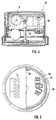
- Fig. 2 shows a water meter 22 of a second embodiment, which also has a mechanical counter 23.
- a reflex disk 24 is associated with this counting device (cf. FIG. 3), which is mechanically coupled to the counter 23 via a drive shaft 25 and which, if operated, is set in rotation by the counting device 23.
- the shaft 25 is coupled with, it always indicates 10 times the respective roller increment by one revolution, i.e., for example, when connected to the right 1 liter roller with one turn of the disc, a consumed amount of 10 liters specified.
- a reflective light barrier 26 is assigned opposite to the reflective light pane, which is covered with corresponding markings, which forms a light barrier with the reflective pane 24 and thus detects the corresponding markings on the reflective pane 24.
- a shield 27 is arranged, which shields any magnetic influence on the signal detection and transmission. After the markings have been detected, corresponding signals are emitted, depending on the operating mode, via the antenna 29 arranged in this example directly underneath an attachment plate 28 which covers the “inner life” of the water meter.
- FIG. 4 describes a third embodiment of a water meter 30, which also has a mechanical counter 31.
- the quantity interval is recorded here purely mechanically.
- a vertically standing shaft 32 is provided is driven either directly from the shaft 33 or indirectly via the roller counter 31 via a transmission gear, not shown.
- a switching cam 34 is arranged on the shaft 32 and actuates the microswitches 35 arranged on both sides when the shaft 32 rotates. Each time one of the switches is actuated, the flow of a predetermined quantity of water is indicated, the respective quantity interval depending on the rotational speed of the shaft 32 and can be adjusted by means of a corresponding configuration of the transmission gear. Instead of the two microswitches 35, only a single one could of course also be provided.
- a signal is also sent to the respective transmission device, after which the operating mode-dependent transmission of the respective count value takes place by means of the antenna 36, which is also arranged on the top in this example.
- FIG. 6 shows a further embodiment of a water meter 37, which also has a mechanical counter 38.
- a shaft 39 is coupled to this counting device 38 and is driven in rotation via the counting device 38.
- Two fork light barriers 41a, 41b are assigned to arm 40 (cf. FIG. 7), between which arm 40 is immersed when it rotates. With each immersion, the respective light barrier 41a or 41b is interrupted, so that the passage of the arm 40 is detected.
- the arrangement of two fork light barriers connected in series means that in the event of a backflow of water, if the arm 40 is rotated in the opposite direction, it will pass through the fork light barrier again and thus indicate a further, the predetermined quantity interval Signal is emitted, an incorrect measurement is prevented, since each signal can be resolved without a doubt.
- the arm 40 is first detected by the light barrier 41b, then by the light barrier 41a, and then runs backwards, the light barrier 41a again sends a signal, but this is not possible with normal forward drive would. In this way, such an erroneous signal can be rejected so that the quantity determination is not affected erroneously.
- the arrangement of two light barriers is of course also possible in the case of the embodiment of FIGS. 2 and 3, the double microswitch arrangement shown in FIGS. 4 and 5 also serving this purpose.
- a water meter with an electronic counting and / or display device is constructed in comparison to the mechanical examples shown in FIGS. 1 to 7 in such a way that an electronic counting device, for example with an LCD display, is arranged instead of the mechanical counting device.
- the operation of the same takes place via a control element, preferably a microprocessor, which is operated via an integrated battery.
- the measurement of the measuring device rotation is not usually done mechanically, but electrically via volume sensors.
- FIG. 8 The integration of the transmitter in such a water meter can now be seen in FIG. 8.
- the electronics of the conventional electronic water meter described are shown in area 12. This consists of a microprocessor 14 operated via a battery 13, which controls the LCD display 15 and is connected to additional elements such as the volume sensors 16, a switch button 17 and an external quartz crystal 18.
- the transmitter is connected to the microprocessor 14 Representing area 19, consisting of the radio device 20 and the transmitting antenna 21.
- the radio device 20 is directly connected to the microprocessor 14 and is controlled by the latter, for example at a predetermined time interval, and thus transmits the measurement results also supplied to the radio device 20 via the microprocessor 14 the antenna 21 to the central receiving system.
Landscapes
- Physics & Mathematics (AREA)
- General Physics & Mathematics (AREA)
- Fluid Mechanics (AREA)
- Electromagnetism (AREA)
- Arrangements For Transmission Of Measured Signals (AREA)
- Measuring Volume Flow (AREA)
- Details Of Flowmeters (AREA)
Applications Claiming Priority (2)
| Application Number | Priority Date | Filing Date | Title |
|---|---|---|---|
| DE4428996 | 1994-08-16 | ||
| DE4428996A DE4428996C2 (de) | 1994-08-16 | 1994-08-16 | Wasserzähler |
Publications (2)
| Publication Number | Publication Date |
|---|---|
| EP0701109A2 true EP0701109A2 (fr) | 1996-03-13 |
| EP0701109A3 EP0701109A3 (fr) | 1996-12-11 |
Family
ID=6525792
Family Applications (1)
| Application Number | Title | Priority Date | Filing Date |
|---|---|---|---|
| EP95112728A Withdrawn EP0701109A3 (fr) | 1994-08-16 | 1995-08-12 | Compteur d'eau |
Country Status (2)
| Country | Link |
|---|---|
| EP (1) | EP0701109A3 (fr) |
| DE (1) | DE4428996C2 (fr) |
Cited By (2)
| Publication number | Priority date | Publication date | Assignee | Title |
|---|---|---|---|---|
| EP1033578A3 (fr) * | 1999-02-27 | 2000-11-02 | Horst Prof. Dr. Ziegler | Dispositif de détermination de la rotation d'un élément rotatif |
| EP2221585A1 (fr) | 2009-02-23 | 2010-08-25 | Lorenz GmbH & Co. KG | Procédé de collecte de données de consommation |
Families Citing this family (15)
| Publication number | Priority date | Publication date | Assignee | Title |
|---|---|---|---|---|
| DE19632575A1 (de) * | 1996-08-13 | 1998-02-19 | Abb Patent Gmbh | Durchflußzähler mit einer von Flüssigkeit durchströmten, zur Erfassung der Durchflußmenge dienenden Meßeinrichtung |
| DE19723364B4 (de) * | 1997-06-04 | 2006-09-14 | Hydrometer Gmbh | Magnetkupplung für Wasserzähler mit Schutz gegen äußere Störmagnetfelder |
| DE29710249U1 (de) * | 1997-06-12 | 1998-10-08 | Raab Karcher Energy Services GmbH, 45131 Essen | Vorrichtung zur Erfassung und Auswertung von temperaturabhängigen Verbrauchswerten |
| DE19755924C2 (de) * | 1997-12-17 | 2001-03-29 | Ifm Electronic Gmbh | Elektronisches Auswertegerät |
| DE19834009A1 (de) * | 1998-07-28 | 2000-02-24 | Micro Sensys Gmbh | Verfahren und Anordnung zur gesicherten Erfassung und Bestätigung des Zählerstandes von Medien- und Energieverbrauchswertzählern |
| DE19839116A1 (de) * | 1998-08-27 | 2000-03-02 | Horst Ziegler | System zur Kontrolle des Verbrauchs eines insbesondere leitungsgebundenen Mediums |
| DE19903789C1 (de) * | 1999-02-01 | 2000-08-03 | Hydrometer Gmbh | Kommunikationsfähiger Durchflußzähler für Flüssigkeiten, insbesondere Wasserzähler |
| DE19922603A1 (de) * | 1999-05-17 | 2000-11-23 | Elster Produktion Gmbh | Verfahren und Vorrichtung zum Fernablesen eines Verbrauchszählers |
| DE19923932C2 (de) * | 1999-05-26 | 2002-08-01 | Hydrometer Gmbh | Flüssigkeitszähler mit multifunktionalem Meßkammerdeckel |
| DE19939535C2 (de) * | 1999-08-20 | 2003-10-09 | Wiesemann & Theis Gmbh | Verfahren zur Funkübertragung eines Statussignals eines Sensors |
| DE19957280A1 (de) * | 1999-11-29 | 2001-05-31 | Elster Produktion Gmbh | Zähler mit Zusatzmodul |
| DE10006804C2 (de) | 2000-02-15 | 2003-09-04 | Berg Prototypen & Design Roland | Reflektor für eine lichttechnische Einrichtung und dessen Verwendung in flächigen Leuchtenkammern, insbesondere Fahrzeugsignalleuchten |
| DE10214418A1 (de) * | 2002-03-30 | 2003-10-09 | Abb Patent Gmbh | Volumenzähler zum Messen eines Flüssigkeitsvolumens |
| DE102006020030A1 (de) * | 2006-04-26 | 2007-11-08 | IAD Gesellschaft für Informatik, Automatisierung und Datenverarbeitung mbH | Datenerfassungs- und Steuerungssystem mit Datenübertragung über Funkstrecken und elektrische Energieverteilnetze und Verfahren hierzu |
| DE202013001852U1 (de) * | 2013-02-27 | 2014-02-28 | Christian Gradischnik | Vorrichtung zum Erfassen eines Durchflusses |
Family Cites Families (17)
| Publication number | Priority date | Publication date | Assignee | Title |
|---|---|---|---|---|
| DE1775155C3 (de) * | 1968-07-10 | 1978-06-08 | Dr.Ing.H.C. F. Porsche Ag, 7000 Stuttgart | Kegelradwendegetriebe mit Gleichlaufeinrichtung |
| DE2221371B2 (de) * | 1972-05-02 | 1974-04-25 | Siemens Ag, 1000 Berlin U. 8000 Muenchen | Einrichtung zur drahtlosen Übertragung eines Meßwerts von einem Meßwertgeber in eine Auswerteschaltung |
| DE2419081C3 (de) * | 1974-04-20 | 1979-02-15 | Bien, Reinhold, 6701 Ruppertsberg | Vorrichtung zur kontaktlosen Messwertübertragung |
| DE2551882C3 (de) * | 1975-11-19 | 1979-03-08 | Fraunhofer-Gesellschaft Zur Foerderung Der Angewandten Forschung E.V., 8000 Muenchen | Vorrichtung zur drahtlosen Fernübertragung der Drehzahl eines sich drehenden Teiles |
| DE2616323A1 (de) * | 1976-04-14 | 1977-10-27 | Kueppers Karl | Durchflussmessgeraet, insbesondere fuer kleine und kleinste durchflussmengen |
| US4119948A (en) * | 1976-04-29 | 1978-10-10 | Ernest Michael Ward | Remote meter reading system |
| DE2854199A1 (de) * | 1978-12-15 | 1980-06-26 | Vdo Schindling | Einrichtung zum uebertragen von messwerten |
| DE2935965B2 (de) * | 1979-09-06 | 1981-07-16 | Kurt 2110 Buchholz Fritze | Anordnung zur telemetrischen Überwachung sich bewegender Maschinenteile. |
| DE3241222C2 (de) * | 1982-11-09 | 1985-03-21 | Hans 6908 Wiesloch Engelmann | Vorrichtung zur Messung der Drehzahl und ggf. der Drehrichtung eines Flügelrades eines Flügelraddurchflußmessers für elektrolytische Flüssigkeiten |
| FR2543292B1 (fr) * | 1983-03-21 | 1986-10-10 | Pont A Mousson | Dispositif de mesure de la rotation d'une turbine de compteurs de debit de fluides |
| JPS60135822A (ja) * | 1983-12-26 | 1985-07-19 | Ricoh Co Ltd | 水道メ−タの自動検針装置 |
| DE3519215A1 (de) * | 1985-04-13 | 1986-10-16 | Ziegler, Horst, Prof. Dr., 4790 Paderborn | Fuehler, insbesondere zur verwendung an einem fluegelraddurchflussmesser |
| US4940976A (en) * | 1988-02-05 | 1990-07-10 | Utilicom Inc. | Automated remote water meter readout system |
| ES2009665A6 (es) * | 1988-11-04 | 1989-10-01 | Perez Lago Alfredo | Sistema de contador optoelectromagnetico analogico digital para liquidos. |
| JPH03215713A (ja) * | 1990-01-20 | 1991-09-20 | Kimmon Mfg Co Ltd | 自動発電式水道メータの発信装置 |
| US5214587A (en) * | 1990-11-28 | 1993-05-25 | Green Richard G | Device for monitoring utility usage |
| DE4123043A1 (de) * | 1991-07-12 | 1993-01-21 | Ingo Dohmann | Anzeigeeinrichtung fuer durchflussmengen an zapfanlagen |
-
1994
- 1994-08-16 DE DE4428996A patent/DE4428996C2/de not_active Revoked
-
1995
- 1995-08-12 EP EP95112728A patent/EP0701109A3/fr not_active Withdrawn
Non-Patent Citations (1)
| Title |
|---|
| None |
Cited By (2)
| Publication number | Priority date | Publication date | Assignee | Title |
|---|---|---|---|---|
| EP1033578A3 (fr) * | 1999-02-27 | 2000-11-02 | Horst Prof. Dr. Ziegler | Dispositif de détermination de la rotation d'un élément rotatif |
| EP2221585A1 (fr) | 2009-02-23 | 2010-08-25 | Lorenz GmbH & Co. KG | Procédé de collecte de données de consommation |
Also Published As
| Publication number | Publication date |
|---|---|
| DE4428996A1 (de) | 1996-02-29 |
| EP0701109A3 (fr) | 1996-12-11 |
| DE4428996C2 (de) | 1997-04-30 |
Similar Documents
| Publication | Publication Date | Title |
|---|---|---|
| EP0701109A2 (fr) | Compteur d'eau | |
| DE19849108C2 (de) | Drehgeber | |
| EP0180880A2 (fr) | Dispositif de détection de la position de l'affichage d'une montre, en particulier une montre à radiocommande | |
| EP0660263A1 (fr) | Compteur à rouleaux à plusieurs chiffres pour un compteur de débit | |
| EP1012430A1 (fr) | Procede et dispositif pour controler l'etat de fermeture de verrous | |
| EP2318982B1 (fr) | Dispositif de lecture des repères de graduation d'un mécanisme de compteur mécanique à rouleaux, sur les compteurs de tous types | |
| WO2006114211A1 (fr) | Fenetre a vitres multiples comportant un element electrique encastre | |
| EP0924379A2 (fr) | Enrouleur de sangle pour un dispositif d'occultation | |
| DE3929879A1 (de) | Parkkarte fuer notrufgesicherte parkhaeuser oder parkgelaende | |
| DE2438055C2 (de) | Frankiermaschine mit einer Eingabeeinrichtung | |
| EP1026481B1 (fr) | Compteur du débit pour liquides capable de communication,en particulier compteur d' eau | |
| DE4309006A1 (de) | Vorrichtung zur drahtlosen Datenübermittlung | |
| DE29603056U1 (de) | Durchflußzähler für Flüssigkeiten | |
| DE19620007A1 (de) | Durchlaufmengenmesser, so Wasserzähler | |
| DE8432847U1 (de) | Zeigerstellungs-Detektionseinrichtung für eine Uhr, insbesondere eine Funkuhr | |
| EP0650107A1 (fr) | Système de commande pour entraînements motorisés | |
| EP0513633B1 (fr) | Montre réveil | |
| EP1890116A1 (fr) | Compteur de liquides infraudable | |
| EP1050747A2 (fr) | Dispositif pour déterminer un volume d'un courant de gaz | |
| DE60108397T2 (de) | Verbrauchszähler | |
| WO1994027256A1 (fr) | Systeme d'enregistrement de peage s'utilisant dans les rues intra-muros et les zones de circulation | |
| DE202020002445U1 (de) | Anordnung zur Erfassung der Schließzyklen eines raumabschließenden Bauelemtes | |
| DE4242549C1 (de) | Einbruchmelderanordnung | |
| DE3125526C2 (de) | Anzeigevorrichtung für Meßinstrumente | |
| EP0701724A1 (fr) | Dispositif pour percevoir une taxe de parking |
Legal Events
| Date | Code | Title | Description |
|---|---|---|---|
| PUAI | Public reference made under article 153(3) epc to a published international application that has entered the european phase |
Free format text: ORIGINAL CODE: 0009012 |
|
| AK | Designated contracting states |
Kind code of ref document: A2 Designated state(s): AT CH DE FR GB IT LI |
|
| PUAL | Search report despatched |
Free format text: ORIGINAL CODE: 0009013 |
|
| AK | Designated contracting states |
Kind code of ref document: A3 Designated state(s): AT CH DE FR GB IT LI |
|
| 17P | Request for examination filed |
Effective date: 19970120 |
|
| 17Q | First examination report despatched |
Effective date: 20000823 |
|
| STAA | Information on the status of an ep patent application or granted ep patent |
Free format text: STATUS: THE APPLICATION IS DEEMED TO BE WITHDRAWN |
|
| 18D | Application deemed to be withdrawn |
Effective date: 20010103 |