EP0701145A2 - Caméra de mesure de distance à images - Google Patents
Caméra de mesure de distance à images Download PDFInfo
- Publication number
- EP0701145A2 EP0701145A2 EP95117494A EP95117494A EP0701145A2 EP 0701145 A2 EP0701145 A2 EP 0701145A2 EP 95117494 A EP95117494 A EP 95117494A EP 95117494 A EP95117494 A EP 95117494A EP 0701145 A2 EP0701145 A2 EP 0701145A2
- Authority
- EP
- European Patent Office
- Prior art keywords
- distance
- receiver
- light
- camera
- light source
- Prior art date
- Legal status (The legal status is an assumption and is not a legal conclusion. Google has not performed a legal analysis and makes no representation as to the accuracy of the status listed.)
- Withdrawn
Links
- 238000003384 imaging method Methods 0.000 title abstract description 4
- 238000011156 evaluation Methods 0.000 claims abstract description 8
- 239000013307 optical fiber Substances 0.000 abstract 1
- 239000011159 matrix material Substances 0.000 description 2
- 238000002310 reflectometry Methods 0.000 description 2
- 239000003086 colorant Substances 0.000 description 1
- 238000005259 measurement Methods 0.000 description 1
- 238000000034 method Methods 0.000 description 1
Images


Classifications
-
- G—PHYSICS
- G01—MEASURING; TESTING
- G01S—RADIO DIRECTION-FINDING; RADIO NAVIGATION; DETERMINING DISTANCE OR VELOCITY BY USE OF RADIO WAVES; LOCATING OR PRESENCE-DETECTING BY USE OF THE REFLECTION OR RERADIATION OF RADIO WAVES; ANALOGOUS ARRANGEMENTS USING OTHER WAVES
- G01S7/00—Details of systems according to groups G01S13/00, G01S15/00, G01S17/00
- G01S7/48—Details of systems according to groups G01S13/00, G01S15/00, G01S17/00 of systems according to group G01S17/00
- G01S7/481—Constructional features, e.g. arrangements of optical elements
- G01S7/4818—Constructional features, e.g. arrangements of optical elements using optical fibres
-
- G—PHYSICS
- G01—MEASURING; TESTING
- G01S—RADIO DIRECTION-FINDING; RADIO NAVIGATION; DETERMINING DISTANCE OR VELOCITY BY USE OF RADIO WAVES; LOCATING OR PRESENCE-DETECTING BY USE OF THE REFLECTION OR RERADIATION OF RADIO WAVES; ANALOGOUS ARRANGEMENTS USING OTHER WAVES
- G01S17/00—Systems using the reflection or reradiation of electromagnetic waves other than radio waves, e.g. lidar systems
- G01S17/88—Lidar systems specially adapted for specific applications
- G01S17/89—Lidar systems specially adapted for specific applications for mapping or imaging
-
- G—PHYSICS
- G01—MEASURING; TESTING
- G01S—RADIO DIRECTION-FINDING; RADIO NAVIGATION; DETERMINING DISTANCE OR VELOCITY BY USE OF RADIO WAVES; LOCATING OR PRESENCE-DETECTING BY USE OF THE REFLECTION OR RERADIATION OF RADIO WAVES; ANALOGOUS ARRANGEMENTS USING OTHER WAVES
- G01S7/00—Details of systems according to groups G01S13/00, G01S15/00, G01S17/00
- G01S7/48—Details of systems according to groups G01S13/00, G01S15/00, G01S17/00 of systems according to group G01S17/00
- G01S7/481—Constructional features, e.g. arrangements of optical elements
- G01S7/4817—Constructional features, e.g. arrangements of optical elements relating to scanning
-
- G—PHYSICS
- G01—MEASURING; TESTING
- G01S—RADIO DIRECTION-FINDING; RADIO NAVIGATION; DETERMINING DISTANCE OR VELOCITY BY USE OF RADIO WAVES; LOCATING OR PRESENCE-DETECTING BY USE OF THE REFLECTION OR RERADIATION OF RADIO WAVES; ANALOGOUS ARRANGEMENTS USING OTHER WAVES
- G01S7/00—Details of systems according to groups G01S13/00, G01S15/00, G01S17/00
- G01S7/48—Details of systems according to groups G01S13/00, G01S15/00, G01S17/00 of systems according to group G01S17/00
- G01S7/481—Constructional features, e.g. arrangements of optical elements
- G01S7/4814—Constructional features, e.g. arrangements of optical elements of transmitters alone
- G01S7/4815—Constructional features, e.g. arrangements of optical elements of transmitters alone using multiple transmitters
Definitions
- the invention relates to a distance image camera.
- a distance image camera is an instrument for scanning and measuring the distance of a room or a scene with objects in the field of view of the camera.
- the distance measurement is based on the transit time measuring principle by means of one or more light sources and detectors.
- the distance or a distance value can be determined by determining the time interval between emitted and received light, reflected by the object to be imaged, and from knowledge of the speed of light.
- a matrix of distance values arises from the fact that serial or parallel point-by-point scanning is carried out over the field of view of the camera.
- the distance values or matrix elements generated in this way can be evaluated directly in a computer or in special electronic circuits and / or can be displayed via a graphics process, for example coding in gray values, grid projection, false colors, and so on, to a display unit such as a monitor.
- the distance image camera is an active principle, an evaluation and / or display of the reflected amplitude information is also possible in addition to obtaining the distance information.
- an amplitude or reflectivity image can also be displayed (in addition to the amplitude of the reflected light (normal photo), the distance information is also taken into account).
- the object of the invention is to propose a distance image camera that is mechanically stable and allows a high recording speed.
- the invention is illustrated by four figures.
- the essential performance parameters of a distance camera are determined by the two-dimensional scanning. Particularly for systems with a larger number of pixels, fast frame rate and long range, the execution of the two-dimensional scanning is, among other things, the performance-determining factor.
- the invention therefore relates to an improvement of the two-dimensional scanning device.
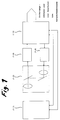
- Fig. 2 shows a distance image camera with electronic line scan.
- the column scanning is achieved mechanically via the mirror 4.3. With this device, mechanical scanning is only necessary in the column, otherwise the entire image generation is carried out electronically.
- a laser diode array 4.1 controlled by drivers and multiplexers, consists of N-laser diode chips, which are attached in a row. The control is serial.
- a light pulse emitted by the laser diode array 4.1 is directed via the imaging optics 4.2, which is part of a biaxial optics (4.2 and 4.2 '), and via the swivel mirror 4.3 to point 4.4 of the scene.
- the light reflected from there returns via the mirror 4.3 to the biaxial optics 4.2 'and from there to the electronic receiver array 4.5.
- the electrical signals generated there arrive in the electronic control and evaluation unit 4.6.
- a distance value is then determined in the electronics 4.6 from the transmit and receive signal.
- Corresponding electronics are proposed, for example, in patent application P 39 15 62
- Fig. 3 shows a distance image camera with purely electronic line scan and mechanical column scanning, but with coaxial optics.
- the light emitted by the laser diode array 5.1 passes through the partially transparent mirror 5.2 and the coaxial optics 5.3 to the swivel mirror 5.5, which carries out the column scan.
- the reflected light pulse is in turn mapped backwards via the mirror 5.5 and the optics 5.3 onto the corresponding detector N of the receiver array 5.4, which is also equipped with multiplexers and receiver circuits.
- the evaluation and determination of the transit time and the distance values of the distance image pixels are carried out in electronics 5.6.
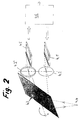
- Fig. 4 shows a completely electronic scanning in both dimensions (rows and columns) without mechanically moving parts, which results in a particularly robust design.
- a two-dimensional laser diode field 6.1 serves as the light source, the light of which is directed via the optics 6.2 to a point 6.3 of the scene. The light reflected from there (6.3) reaches the corresponding pixel of the receiver diode array 6.4 again via the optics 6.2 shown here biaxially.
- the control and evaluation takes place in the electronics unit 6.5.
- the laser diode array 6.1 and the receiver diode array 6.4 are rectangular and flat here. In coordination with the optics 6.2, curved fields are also possible do not have to have a rectangular cross-section.
- FIGS. 2 and 4 can also be designed as coaxial optics with a different optic design, as FIG. 3 shows by way of example.
Landscapes
- Engineering & Computer Science (AREA)
- Physics & Mathematics (AREA)
- Computer Networks & Wireless Communication (AREA)
- General Physics & Mathematics (AREA)
- Radar, Positioning & Navigation (AREA)
- Remote Sensing (AREA)
- Electromagnetism (AREA)
- Optical Radar Systems And Details Thereof (AREA)
- Measurement Of Optical Distance (AREA)
- Image Input (AREA)
- Vehicle Body Suspensions (AREA)
- Length Measuring Devices By Optical Means (AREA)
- Closed-Circuit Television Systems (AREA)
- Transforming Light Signals Into Electric Signals (AREA)
Applications Claiming Priority (3)
| Application Number | Priority Date | Filing Date | Title |
|---|---|---|---|
| DE3942770 | 1989-12-23 | ||
| DE3942770A DE3942770A1 (de) | 1989-12-23 | 1989-12-23 | Entfernungsbildkamera |
| EP90122830A EP0435011B1 (fr) | 1989-12-23 | 1990-11-29 | Caméra de mesure de distance à images |
Related Parent Applications (2)
| Application Number | Title | Priority Date | Filing Date |
|---|---|---|---|
| EP90122830A Division EP0435011B1 (fr) | 1989-12-23 | 1990-11-29 | Caméra de mesure de distance à images |
| EP90122830.4 Division | 1990-11-29 |
Publications (2)
| Publication Number | Publication Date |
|---|---|
| EP0701145A2 true EP0701145A2 (fr) | 1996-03-13 |
| EP0701145A3 EP0701145A3 (fr) | 1996-03-20 |
Family
ID=6396303
Family Applications (2)
| Application Number | Title | Priority Date | Filing Date |
|---|---|---|---|
| EP90122830A Expired - Lifetime EP0435011B1 (fr) | 1989-12-23 | 1990-11-29 | Caméra de mesure de distance à images |
| EP95117494A Withdrawn EP0701145A3 (fr) | 1989-12-23 | 1990-11-29 | Caméra de mesure de distance à images |
Family Applications Before (1)
| Application Number | Title | Priority Date | Filing Date |
|---|---|---|---|
| EP90122830A Expired - Lifetime EP0435011B1 (fr) | 1989-12-23 | 1990-11-29 | Caméra de mesure de distance à images |
Country Status (5)
| Country | Link |
|---|---|
| US (1) | US5225876A (fr) |
| EP (2) | EP0435011B1 (fr) |
| AT (1) | ATE148795T1 (fr) |
| DE (2) | DE3942770A1 (fr) |
| ES (1) | ES2099701T3 (fr) |
Cited By (3)
| Publication number | Priority date | Publication date | Assignee | Title |
|---|---|---|---|---|
| EP1065522A3 (fr) * | 1999-06-30 | 2001-03-07 | Sick AG | Système de surveillance optoélectronique |
| US6636300B2 (en) | 1999-03-18 | 2003-10-21 | Siemens Aktiengesellschaft | Spatially resolving range-finding system |
| CN100385330C (zh) * | 2005-05-26 | 2008-04-30 | 中国科学院长春光学精密机械与物理研究所 | 一种采用光纤变维器的长线阵探测器拼接方法及装置 |
Families Citing this family (34)
| Publication number | Priority date | Publication date | Assignee | Title |
|---|---|---|---|---|
| DE4107850B4 (de) * | 1990-03-10 | 2006-06-29 | Daimlerchrysler Ag | Anordnung zur Verbesserung der Sicht, insbesondere in Fahrzeugen |
| DE4222642A1 (de) * | 1992-07-10 | 1994-01-13 | Bodenseewerk Geraetetech | Bilderfassende Sensoreinheit |
| DE4320485B4 (de) * | 1993-06-21 | 2007-04-19 | Eads Deutschland Gmbh | Verfahren zur Objektvermessung mittels intelligenter Entfernungsbildkamera |
| DE59402247D1 (de) * | 1993-08-13 | 1997-04-30 | Putzmeister Maschf | Verfahren zur bearbeitung eines objektes, insbesondere eines flugzeugs |
| DE4330845C1 (de) * | 1993-09-11 | 1994-12-15 | Fraunhofer Ges Forschung | Verfahren zur Bearbeitung eines Objekts mittels eines mindestens eine Bearbeitungseinheit aufweisenden Bearbeitungsgeräts |
| JPH0886641A (ja) * | 1994-09-16 | 1996-04-02 | Olympus Optical Co Ltd | 投受光式焦点検出装置 |
| US5752100A (en) * | 1996-01-26 | 1998-05-12 | Eastman Kodak Company | Driver circuit for a camera autofocus laser diode with provision for fault protection |
| US5889593A (en) * | 1997-02-26 | 1999-03-30 | Kla Instruments Corporation | Optical system and method for angle-dependent reflection or transmission measurement |
| DE19709097C2 (de) * | 1997-03-06 | 1999-02-04 | Dornier Gmbh | Flugführungssystem für tieffliegende Fluggeräte |
| US6697557B2 (en) * | 2000-10-04 | 2004-02-24 | University Of South Florida | Two-dimensional optical filter and associated methods |
| DE10252523A1 (de) * | 2001-11-16 | 2003-07-03 | Ccs Inc | Beleuchtungsvorrichtung zur optischen Prüfung |
| DE10305010B4 (de) | 2003-02-07 | 2012-06-28 | Robert Bosch Gmbh | Vorrichtung und Verfahren zur Bilderzeugung |
| DE102004031097B4 (de) * | 2004-06-28 | 2012-02-09 | Diehl Bgt Defence Gmbh & Co. Kg | Lasermessgerät |
| JP2006125862A (ja) * | 2004-10-26 | 2006-05-18 | Sharp Corp | 光学式測距センサ、自走式掃除機およびエアコン |
| US10148897B2 (en) * | 2005-07-20 | 2018-12-04 | Rearden, Llc | Apparatus and method for capturing still images and video using coded lens imaging techniques |
| EP1792775B1 (fr) * | 2005-12-02 | 2018-03-07 | Volkswagen Aktiengesellschaft | Véhicule et capteur pour détecter des obstacles dans le voisinage du véhicule |
| US8019490B2 (en) * | 2006-09-29 | 2011-09-13 | Applied Minds, Llc | Imaging and display system to aid helicopter landings in brownout conditions |
| DE102007014015B4 (de) | 2007-03-23 | 2010-07-01 | Eads Deutschland Gmbh | Mensch-Maschinen-Interface zur Pilotenunterstützung bei Start und Landung eines Fluggeräts bei verminderter Außensicht |
| RU2396574C2 (ru) * | 2008-09-04 | 2010-08-10 | Федеральное государственное унитарное предприятие "Производственное объединение "Уральский оптико-механический завод" имени Э.С. Яламова" | Теплопеленгатор |
| ATE539366T1 (de) | 2009-10-10 | 2012-01-15 | Eads Deutschland Gmbh | Faseroptischer scanner |
| US10739460B2 (en) * | 2010-08-11 | 2020-08-11 | Apple Inc. | Time-of-flight detector with single-axis scan |
| US9784577B2 (en) * | 2012-03-16 | 2017-10-10 | Lg Innotek Co., Ltd. | Measuring distance from object by using size of pattern projected onto object |
| US10488535B2 (en) | 2013-03-12 | 2019-11-26 | Rearden, Llc | Apparatus and method for capturing still images and video using diffraction coded imaging techniques |
| US20150260830A1 (en) * | 2013-07-12 | 2015-09-17 | Princeton Optronics Inc. | 2-D Planar VCSEL Source for 3-D Imaging |
| DE102013012789A1 (de) * | 2013-07-31 | 2015-02-05 | Valeo Schalter Und Sensoren Gmbh | Abtastende optoelektronische Detektionseinrichtung und Kraftfahrzeug mit einer solchen Detektionseinrichtung |
| JP6671629B2 (ja) * | 2015-03-18 | 2020-03-25 | 株式会社リコー | 物体検出装置、センシング装置、及び移動体装置 |
| WO2017176410A1 (fr) * | 2016-04-08 | 2017-10-12 | Apple Inc. | Détecteur de temps de vol avec balayage à un seul axe |
| US10298913B2 (en) | 2016-08-18 | 2019-05-21 | Apple Inc. | Standalone depth camera |
| JP6594282B2 (ja) * | 2016-10-06 | 2019-10-23 | オムロンオートモーティブエレクトロニクス株式会社 | レーザレーダ装置 |
| US10598771B2 (en) * | 2017-01-18 | 2020-03-24 | Analog Devices Global Unlimited Company | Depth sensing with multiple light sources |
| KR102430667B1 (ko) * | 2017-03-24 | 2022-08-09 | 주식회사 히타치엘지 데이터 스토리지 코리아 | 거리 측정 장치 |
| CN113466882B (zh) | 2017-07-05 | 2026-03-24 | 奥斯特公司 | 光测距装置 |
| KR102623533B1 (ko) * | 2018-08-10 | 2024-01-11 | 오로라 오퍼레이션스, 인크. | 콜리메이트된 빔들의 팬을 이용한 코히런트 lidar의 스캐닝을 위한 방법 및 시스템 |
| JP7596810B2 (ja) * | 2021-01-22 | 2024-12-10 | Toppanホールディングス株式会社 | 距離画像撮像装置及び距離画像撮像方法 |
Family Cites Families (17)
| Publication number | Priority date | Publication date | Assignee | Title |
|---|---|---|---|---|
| US3523730A (en) * | 1964-02-05 | 1970-08-11 | Singer General Precision | Optical object locating system |
| FR1601413A (fr) * | 1968-06-26 | 1970-08-24 | ||
| US3682553A (en) * | 1968-09-19 | 1972-08-08 | Optics Technology Inc | Apparatus for acquiring and laying real time 3-d information |
| US4199253A (en) * | 1978-04-19 | 1980-04-22 | Solid Photography Inc. | Methods and systems for three-dimensional measurement |
| AU7811881A (en) * | 1980-12-09 | 1982-06-17 | John Leonard Hughes | Variable beamwidth laser radar systems |
| JPS5810833A (ja) * | 1981-07-14 | 1983-01-21 | Hitachi Ltd | パタ−ンの検出方法及び同装置 |
| JPS6060511A (ja) * | 1983-09-14 | 1985-04-08 | Asahi Optical Co Ltd | 測距装置 |
| DE3404396A1 (de) * | 1984-02-08 | 1985-08-14 | Dornier Gmbh, 7990 Friedrichshafen | Vorrichtung und verfahren zur aufnahme von entfernungsbildern |
| US4687325A (en) * | 1985-03-28 | 1987-08-18 | General Electric Company | Three-dimensional range camera |
| US4687326A (en) * | 1985-11-12 | 1987-08-18 | General Electric Company | Integrated range and luminance camera |
| US4698498A (en) * | 1986-04-28 | 1987-10-06 | Robot Defense Systems, Inc. | Three-dimensional laser imaging transmitter/receiver |
| JPS63316476A (ja) * | 1987-06-18 | 1988-12-23 | Seiko Instr & Electronics Ltd | 半導体装置およびその製造方法 |
| DE3732347C1 (de) * | 1987-09-25 | 1989-03-16 | Messerschmitt Boelkow Blohm | Entfernungsbild-Sensor |
| DE3840425A1 (de) * | 1987-09-25 | 1990-06-07 | Messerschmitt Boelkow Blohm | Entfernungsbild-sensor |
| US4927263A (en) * | 1988-08-15 | 1990-05-22 | The Perkin-Elmer Corporation | Position and velocity imaging system using 2-D laser diode array |
| DE3915627A1 (de) * | 1989-05-12 | 1990-11-15 | Dornier Luftfahrt | Optisches radar |
| US4957362A (en) * | 1989-09-08 | 1990-09-18 | Environmental Research Institute Of Michigan | Method and apparatus for electro-optical phase detection |
-
1989
- 1989-12-23 DE DE3942770A patent/DE3942770A1/de active Granted
-
1990
- 1990-11-29 EP EP90122830A patent/EP0435011B1/fr not_active Expired - Lifetime
- 1990-11-29 DE DE59010644T patent/DE59010644D1/de not_active Expired - Lifetime
- 1990-11-29 ES ES90122830T patent/ES2099701T3/es not_active Expired - Lifetime
- 1990-11-29 AT AT90122830T patent/ATE148795T1/de not_active IP Right Cessation
- 1990-11-29 EP EP95117494A patent/EP0701145A3/fr not_active Withdrawn
- 1990-12-21 US US07/632,051 patent/US5225876A/en not_active Expired - Fee Related
Non-Patent Citations (1)
| Title |
|---|
| None |
Cited By (3)
| Publication number | Priority date | Publication date | Assignee | Title |
|---|---|---|---|---|
| US6636300B2 (en) | 1999-03-18 | 2003-10-21 | Siemens Aktiengesellschaft | Spatially resolving range-finding system |
| EP1065522A3 (fr) * | 1999-06-30 | 2001-03-07 | Sick AG | Système de surveillance optoélectronique |
| CN100385330C (zh) * | 2005-05-26 | 2008-04-30 | 中国科学院长春光学精密机械与物理研究所 | 一种采用光纤变维器的长线阵探测器拼接方法及装置 |
Also Published As
| Publication number | Publication date |
|---|---|
| ATE148795T1 (de) | 1997-02-15 |
| DE59010644D1 (de) | 1997-03-20 |
| EP0435011A3 (en) | 1992-03-11 |
| US5225876A (en) | 1993-07-06 |
| EP0435011A2 (fr) | 1991-07-03 |
| ES2099701T3 (es) | 1997-06-01 |
| EP0701145A3 (fr) | 1996-03-20 |
| DE3942770C2 (fr) | 1992-01-16 |
| DE3942770A1 (de) | 1991-07-11 |
| EP0435011B1 (fr) | 1997-02-05 |
Similar Documents
| Publication | Publication Date | Title |
|---|---|---|
| EP0701145A2 (fr) | Caméra de mesure de distance à images | |
| EP0396865B1 (fr) | Radar optique | |
| AT412028B (de) | Einrichtung zur aufnahme eines objektraumes | |
| DE3788734T2 (de) | Vorrichtung zum Abtasten eines optischen Kodes. | |
| DE69207176T2 (de) | Optischer Sensor | |
| DE69635858T2 (de) | Telezentrische 3d kamera und zugehöriges verfahren | |
| DE69834053T2 (de) | Ccd-basierter bar-kode-scanner | |
| EP0895604B1 (fr) | Procede et dispositif de mesure pour determiner la position d'un objet | |
| DE3916362C2 (de) | Anordnung zum Übertragen eines ein Informationssignal tragenden Lichtstrahls durch die Atmosphäre | |
| DE69116270T2 (de) | Verfahren und vorrichtung zur bestimmung der position von mindestens einer anschlussfahne eines elektronischen bauelements | |
| EP1321777A2 (fr) | Procédé de prise de vues d'un espace objet | |
| DE3007893C2 (de) | Wärmebildgerät | |
| DE3423135A1 (de) | Verfahren zum auslesen einer entfernungsbildzeile | |
| DE19603267A1 (de) | Vorrichtung zur Abstands- und/oder Positionsbestimmung | |
| DE69504957T2 (de) | Sehhilfe für blinde | |
| EP0495190A2 (fr) | Dispositif pour la mesure optique d'un angle, en particulier de la position des roues d'automobiles dans un plan vertical | |
| EP1248120A2 (fr) | Chercheur à double mode | |
| DE69716393T3 (de) | Vorrichtung zum Abtasten eines sich auf einem bewegenden Artikel befindlichen optischen Kodes und Verfahren zum Abtasten eines solchen optischen Kodes mittels dieser Abtastvorrichtung | |
| DE3885017T2 (de) | Einrichtung zur selektiven Detektion von Objekten. | |
| AT412029B (de) | Verfahren zur aufnahme eines objektraumes | |
| DE3641258C2 (fr) | ||
| DE102020116513A1 (de) | Erweiterte deltacodierungstechnik zur lidarrohdatenkomprimierung | |
| DE4142097B4 (de) | Abstandsmeßgerät | |
| DE2850743C3 (de) | Verfahren und Vorrichtung zur Messung der Abweichung des Sendestrahls von der optischen Achse des Empfangsteleskops bei einem Lidargerät | |
| EP0000067A1 (fr) | Procédé pour l'examen par ultrasons et pour la représentation d'un objet |
Legal Events
| Date | Code | Title | Description |
|---|---|---|---|
| PUAI | Public reference made under article 153(3) epc to a published international application that has entered the european phase |
Free format text: ORIGINAL CODE: 0009012 |
|
| PUAL | Search report despatched |
Free format text: ORIGINAL CODE: 0009013 |
|
| AC | Divisional application: reference to earlier application |
Ref document number: 435011 Country of ref document: EP |
|
| AK | Designated contracting states |
Kind code of ref document: A2 Designated state(s): AT BE CH DE ES FR GB IT LI NL SE |
|
| AK | Designated contracting states |
Kind code of ref document: A3 Designated state(s): AT BE CH DE ES FR GB IT LI NL SE |
|
| RIN1 | Information on inventor provided before grant (corrected) |
Inventor name: EIBERT, MAX, DR. Inventor name: LUX, PETER, DR. |
|
| 17P | Request for examination filed |
Effective date: 19960924 |
|
| 17Q | First examination report despatched |
Effective date: 19981127 |
|
| STAA | Information on the status of an ep patent application or granted ep patent |
Free format text: STATUS: THE APPLICATION IS DEEMED TO BE WITHDRAWN |
|
| 18D | Application deemed to be withdrawn |
Effective date: 19990608 |