EP0701308B1 - Vorrichtung zum Beschalten einer verstärkenden Faser - Google Patents
Vorrichtung zum Beschalten einer verstärkenden Faser Download PDFInfo
- Publication number
- EP0701308B1 EP0701308B1 EP95111641A EP95111641A EP0701308B1 EP 0701308 B1 EP0701308 B1 EP 0701308B1 EP 95111641 A EP95111641 A EP 95111641A EP 95111641 A EP95111641 A EP 95111641A EP 0701308 B1 EP0701308 B1 EP 0701308B1
- Authority
- EP
- European Patent Office
- Prior art keywords
- switch
- output
- input
- integrated
- optical
- Prior art date
- Legal status (The legal status is an assumption and is not a legal conclusion. Google has not performed a legal analysis and makes no representation as to the accuracy of the status listed.)
- Expired - Lifetime
Links
Images


Classifications
-
- H—ELECTRICITY
- H04—ELECTRIC COMMUNICATION TECHNIQUE
- H04B—TRANSMISSION
- H04B10/00—Transmission systems employing electromagnetic waves other than radio-waves, e.g. infrared, visible or ultraviolet light, or employing corpuscular radiation, e.g. quantum communication
- H04B10/27—Arrangements for networking
-
- H—ELECTRICITY
- H01—ELECTRIC ELEMENTS
- H01S—DEVICES USING THE PROCESS OF LIGHT AMPLIFICATION BY STIMULATED EMISSION OF RADIATION [LASER] TO AMPLIFY OR GENERATE LIGHT; DEVICES USING STIMULATED EMISSION OF ELECTROMAGNETIC RADIATION IN WAVE RANGES OTHER THAN OPTICAL
- H01S3/00—Lasers, i.e. devices using stimulated emission of electromagnetic radiation in the infrared, visible or ultraviolet wave range
- H01S3/05—Construction or shape of optical resonators; Accommodation of active medium therein; Shape of active medium
- H01S3/06—Construction or shape of active medium
- H01S3/063—Waveguide lasers, i.e. whereby the dimensions of the waveguide are of the order of the light wavelength
- H01S3/067—Fibre lasers
- H01S3/06754—Fibre amplifiers
-
- H—ELECTRICITY
- H04—ELECTRIC COMMUNICATION TECHNIQUE
- H04B—TRANSMISSION
- H04B10/00—Transmission systems employing electromagnetic waves other than radio-waves, e.g. infrared, visible or ultraviolet light, or employing corpuscular radiation, e.g. quantum communication
- H04B10/27—Arrangements for networking
- H04B10/275—Ring-type networks
-
- H—ELECTRICITY
- H04—ELECTRIC COMMUNICATION TECHNIQUE
- H04B—TRANSMISSION
- H04B10/00—Transmission systems employing electromagnetic waves other than radio-waves, e.g. infrared, visible or ultraviolet light, or employing corpuscular radiation, e.g. quantum communication
- H04B10/29—Repeaters
- H04B10/291—Repeaters in which processing or amplification is carried out without conversion of the main signal from optical form
-
- H—ELECTRICITY
- H04—ELECTRIC COMMUNICATION TECHNIQUE
- H04B—TRANSMISSION
- H04B10/00—Transmission systems employing electromagnetic waves other than radio-waves, e.g. infrared, visible or ultraviolet light, or employing corpuscular radiation, e.g. quantum communication
- H04B10/29—Repeaters
- H04B10/291—Repeaters in which processing or amplification is carried out without conversion of the main signal from optical form
- H04B10/2912—Repeaters in which processing or amplification is carried out without conversion of the main signal from optical form characterised by the medium used for amplification or processing
-
- H—ELECTRICITY
- H01—ELECTRIC ELEMENTS
- H01S—DEVICES USING THE PROCESS OF LIGHT AMPLIFICATION BY STIMULATED EMISSION OF RADIATION [LASER] TO AMPLIFY OR GENERATE LIGHT; DEVICES USING STIMULATED EMISSION OF ELECTROMAGNETIC RADIATION IN WAVE RANGES OTHER THAN OPTICAL
- H01S3/00—Lasers, i.e. devices using stimulated emission of electromagnetic radiation in the infrared, visible or ultraviolet wave range
- H01S3/05—Construction or shape of optical resonators; Accommodation of active medium therein; Shape of active medium
- H01S3/06—Construction or shape of active medium
- H01S3/063—Waveguide lasers, i.e. whereby the dimensions of the waveguide are of the order of the light wavelength
- H01S3/067—Fibre lasers
- H01S3/06754—Fibre amplifiers
- H01S3/06787—Bidirectional amplifier
Definitions
- the invention is based on a device for wiring a reinforcing fiber of the genus Main claim. It is already a device for wiring a reinforcing fiber by Bambach, et al. "DIAMOND - on economic solution for the introduction of digital transmission of analog and digital audio and video signals ", FITCE, European Tele Communications Days 1993, Antwerp August 29, 1993 to September 4, 1993, known for up to four discrete switches are arranged, which ensure that a reinforcing fiber that is inserted into a ring system is independent of the direction of transmission of the optical Signals always in the specified direction of amplification is operated.
- the use of four optical switches requires a relatively large amount of circuitry.
- a reinforcing optical fiber is arranged, or it two discrete switches are required.
- the reinforcing Fiber and a connected pump laser provide one Fiber amplifier.
- the fiber amplifier has one Directional coupler on, for coupling or decoupling signals is used for an optical network.
- a device according to the preamble of claim 1 is in Lasers and Electro-optics Society Annual Meeting Conference Proceedings, Boston, Nov. 4-9, 1990, Vol. 2, Pages 250-254.
- the inventive device with the features of independent claim 1 has the advantage that the optical lines and the reinforcing fiber on one integrated optical circuit are connected and the optical directional coupler on the integrated optical Circuit is integrated. By integrating the Directional coupler, the device is downsized. The Using an integrated optical circuit for the Wiring the reinforcing fiber leads to a inexpensive implementation of the circuit.
- An advantageous development of the invention Device is achieved by using a one-by-two switch and a two-times on-switch are integrated, over the two input and two output lines with the optical fiber amplifiers are connected.
- Another embodiment of the device according to the invention is achieved by having two additional one-by-two switches are arranged, the one input and one Output line with the two two-by-one switches connect.
- Another advantageous embodiment of the device exists in it, two input and two output lines over two Two-by-two switches with the two two-by-one switches connect to. In this way, the most varied Switching combinations of the input lines and Output lines enabled. So that the optical Signals integrated on a variety of variants optical circuit and supplied by the integrated optical circuit can be dissipated and still is on simple way to amplify and decouple the signals possible.
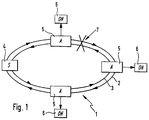
- FIG. 1 shows a fiber ring system
- FIG. 2 an integrated optical circuit with a two-by-one switch and a one-by-two switch
- Figure 3 one integrated otic circuit with a two-by-one output switch
- Figure 4 is an integrated optical Circuit with four two-by-one switches
- Figure 5 one integrated optical circuit with a two-by-two switch
- 6 shows an integrated optical circuit with two two-by-two switches and two two-by-one switches
- Figure 7 is an integrated optical Circuit 8 with isolators.
- FIG. 1 shows a fiber ring system that has a transmitter 4 has that over two ring lines 2, 3 with three Junction points 5 is connected.
- the ring lines 2,3 can be realized by one and the same fiber.
- the first ring line 2 transmits data in the form of optical Signals clockwise.
- the signals are from Transmitter 4 broadcast clockwise and over the three Junction points 5 looped through to transmitter 4.
- the transmitter 4 can also counter the signals Send clockwise over the second ring line 3.
- the signals go through the three Junction points 5 looped through and to the transmitter 4 returned.
- the branch points 5 reinforce by means of the signals and of a directional fiber amplifier duplicate those transmitted via the ring line 2, 3 Give signals using an optical directional coupler and this to an optical network 6.
- An optical one Network 6 consists, for example, of a large number of Receiving devices such as televisions or Radios.
- the transmitter 4 receives the signal sent by it no more. This causes the transmitter 4 in to send in both directions if the transmitter is not already in sends in both directions. It must be ensured that in the Junction points 5, which are now the data from another Direction are supplied, a switch of the switch is made so that the directional fiber amplifiers the junction points 5 in the given direction Signals are fed.
- Figure 2 shows an integrated optical circuit 8 in the form of an integrated chip that acts as an integrated waveguide a first input line 22 and a second Input line 23 has two inputs one first switch 18 are guided, the two-by-one switch is executed.
- first and second Input line 22, 23 are two optical lines coupled, e.g. represented by ring lines 2,3 will.
- the optical lines are on accordingly trained connections of the integrated optical circuit 8 coupled.
- Integrated optical circuits are known and will be e.g. in the form of a semiconductor chip with integrated optical waveguides or using an impression technique in made of an impressionable material, e.g. in the still unpublished patent application DE-OS 4401219 is described.
- An output of the first switch 18 is via a first one Input light guide 20 with a first reinforcing fiber 12, in particular with an erbium-doped fiber, connected.
- the second end of the first fiber 12 is one first output light guide 21 connected to a Input of a second switch 19 performed as a one-by-two switch is executed.
- the two exits of the second Switch 19 are connected to a first output line 24 and connected to a second output line 25.
- To the first and the second output line 24, 25 are optical lines e.g. Ring lines 2.3 coupled.
- the optical lines are connected to appropriately trained connections integrated optical circuit connected.
- the first reinforcing fiber 12 is not integrated integrated optical circuit 8, but via connections optically coupled.
- a pump laser 9 is also connected to the integrated optical circuit 8 connected and over a first light guide 10 to a first wavelength-selective directional coupler 11 out.
- the first Directional coupler 11 is connected to the first input light guide 20 in coupled in such a way that the output from the pump laser 9 Led light output to the first reinforcing fiber 12 becomes.
- the control unit 15 is via a first control line 16 to the second switch 19 and via a second control line 17 to the first Switch 18 connected.
- the pump laser 9, the optical Network 6, the optical lines and the control unit 15 are optical to the integrated optical circuit 8 coupled.
- the optical lines are in shape in FIG represented schematically by arrows.
- An adjustment of the fields is preferably used Single-mode waveguide with different Core diameters made.
- the reinforcing fiber 12 to the waveguide integrated optical circuit 8 via integrated taper 78 adapted to create an adiabatic transition.
- Taper are e.g. out K.J.Ebeling, "Integrated Optics", Springer Verlag Berlin, 1989 pp. 106ff. known.
- a light signal is transmitted via the first input line 22 the first switch 18 and the first input light guide 20 led to the reinforcing fiber 12.
- the reinforcing fiber 12 is supplied by the pump laser 9 with pump energy, so that supplied light signal is amplified. That reinforced Light signal is from the amplifying fiber 12 over the second switch 19 to the second output line 25 passed on. In addition, the increased light output via the third optical directional coupler 14 to the optical Network 6 passed.
- the control unit 15 is on the fifth output light pipe 33 also one of the amplified light signal dependent light signal supplied. The control unit 15 checks whether a light signal from the first fiber 12 is released. If this is the case, it remains the position of the first and second switches 18, 19 unchanged.
- the first switch 18 to the second Input line 23 and the second switch 19 to the first Output line 24 switched. This way a failure of the first input line 22 achieved that is switched to the second input line 23. As well is from the second output line 25 to the first Output line 24 switched. This ensures that regardless of the input line used, the first reinforcing fiber 12 the first directional coupler 11, the second Directional coupler 13 and the third directional coupler 14 in the given direction with light signals.
- Optical fiber amplifiers with the corresponding ones are already known and for example in the Brochure, "Fiber amplifier OFA 151 AB", No. 018517, 03/94 described by ANT, Bosch Telecom.
- Optical switches also function as one-by-two, Two times one and two times two known.
- P. 95ff. is, for example, a two by two optical Switch described.
- Figure 3 shows an integrated optical circuit 8, the first and second reinforcing fibers 12, 76 having.
- a third input 56 of the integrated optical Circuit 8 is connected to the first input light guide 20 connected to one end of the first reinforcing fiber 12 is connected.
- the second end of the first reinforcing fiber 12 is with the first Output light guide 21 leading to a fifth output 60 is connected.
- a fourth input 57 is at one third input light guide 29 connected to the second reinforcing fiber 76 is connected.
- the output of the second amplifying fiber 76 is at one second output light guide 30 connected to a third output 58 is connected.
- the pump laser 9 is over a first light guide 10 and a distribution coupler 80 a first directional coupler 11 and a fifth Directional coupler 27 connected.
- the first directional coupler 11 is to the first input light guide 20 and the fifth Directional coupler 27 is on the third input light guide 29 coupled.
- a sixth directional coupler 34 is on the second Output light guide 30 coupled and with a first Input of a twelfth two-by-one switch 77 connected.
- a seventh directional coupler 35 is on the first Input light guide 21 coupled and to a second Input of the twelfth switch 77 connected.
- the exit of twelfth switch 77 is over a fourth Output light line 32 with an optical network 6 connected.
- An eighth directional coupler 36 is on the fourth Output fiber 32 connected and with a Control unit 15 connected.
- the control unit 15 is with a second control line 17 to the twelfth switch 77 connected.
- To the third and fourth inputs 56, 57 and at the third and fifth outputs 57.60 are optical Conductors connected, e.g. formed as ring lines are.
- the optical conductors are schematic in FIG shown as arrows.
- a light signal is sent to the first fiber 12 passed, which is amplified by the pump laser 9 and is output at the fifth output 60, one Decoupling the output signal via the twelfth switch 77 to the optical network 6.
- Control unit 15 determines that at the output of the twelfth switch 77 no light signal is output, the input of the twelfth switch 77 on the output of the second fiber 76 switched. In this way it is achieved that when over the third input 56 is no longer supplied with a light signal and the supply of the light signal via the fourth input 57 takes place, then a decoupling of the light signal on the second fiber 76 is switched and thus the optical Network 6 continues to be supplied with light signals.
- Figure 4 shows an integrated optical circuit 8 with four Switches 44, 45, 46, 47 and a first amplifying Fiber 12.
- a first port 61 is connected to an input of a third switch 44 connected.
- the third switch 44 is depending on the direction of operation as a one-by-two switch or as Two-times on switch trained.
- An exit of the third Switch 44 is connected via a first connecting line 49 connected to an input of a fourth switch 45.
- Of the fourth switch 45 is a two-times on switch educated.
- the output of the fourth switch 45 is over a first input light guide 20 with the first reinforcing fiber 12 connected.
- a pump laser 9 is over a first light guide 10 to a ninth directional coupler 37 connected to the first input light guide 20 is coupled.
- the exit of the first reinforcing fiber 12 is connected to a first output light guide 21, which is connected to an input of a sixth switch 47 is.
- the sixth switch 47 is a one-by-two switch educated.
- An eleventh directional coupler 39 is on the first Output light guide 21 coupled and a fifth Output light line 33 with a control unit 15 connected.
- a tenth directional coupler 38 is also on the first output light guide 21 coupled and via a fifth output line 55 with an optical network 6 connected.
- a first output of the sixth switch 47 is via a second optical connecting line 50 with a first input of a fifth switch 46 connected.
- Of the fifth switch 46 is a two-by-one switch, depending on the operating direction or as a one-by-two switch educated.
- the output of the fifth switch 46 is with connected to a second terminal 62.
- a second entrance to the fifth switch 46 is via a fourth optical Connection line 52 with a second input of the fourth Switch 45 connected.
- a second exit of the third Switch 44 is via a third optical Connection line 51 with a second output of the sixth Switch 47 connected.
- the control unit 15 is via a fourth control line 54 with the fifth switch 46, via a third control line 53 with the third switch 44, via a second control line 17 with the fourth switch 45 and via a first control line 16 to the sixth Switch 47 connected.
- On the first and the second Connection 61, 62 are optical lines, e.g. Ring lines, connected.
- the pump laser 9 reinforced the supplied light signal in the first fiber 12.
- the first Fiber 12 gives an amplified light signal over the sixth Switch 47 and the fifth switch 46 to the second Connection 62.
- the tenth directional coupler 38 the amplified light signal of the first fiber 12 to the optical network 6 output.
- the control unit 15 monitors the output of the first fiber 12. If the monitoring of the first fiber 12 reveals that none Light signal is output, so the third switch 44, the fourth switch 45, the fifth switch 46 and the seventh switch 48 switched so that light signals via the second connection 62 to the integrated optical Circuit 8 are performed on the fifth switch 46 and the fourth switch 45 to the first input light guide 20 be guided and that reinforced by the first fiber 12 Light signals via the sixth switch 47 and the third Switches 44 are output to the first terminal 61. On this way it is achieved that although the light signals are now are supplied via the second connection 62 and via the first connection 61 are led away, the light signals be amplified and decoupled from the optical network 6 will. Thus, even if the Data transmission direction a decoupling of the light signals to maintain the optical network 6.
- Figure 5 shows an integrated optical circuit 8, the has a seventh switch 48, which acts as a two-by-two switch is trained.
- Figure 5 corresponds to essential of Figure 4, but instead of the two One-by-two switch and the two two-by-one switches a two-by-two switch 48 is arranged.
- a first one Input / output 78 of the seventh switch 48 is with the first Connection 61 connected.
- a second input / output 79 of the Seventh switch 48 is connected to the second terminal 62 connected.
- a third input / output 80 of the seventh switch 48 is connected to the first input light guide 20.
- a fourth input / output 81 of the seventh switch 48 is connected connected to the first output light guide 21.
- the pump laser 9 is over the first light guide 10 and a ninth directional optical directional coupler 37 to the first Input light guide 20 connected.
- the first Input light guide 20 is connected via the first fiber 12 to the first output light guide 21 connected.
- About one eleventh directional optical directional coupler 39 and one fifth output light line 33 is a control unit 15 with connected to the first output light guide 21.
- About one tenth directional coupler 38 is through a fifth output line 55 an optical network 6 with the first Output light guide 21 connected.
- the first and the second connection 61, 62 are optical lines, in particular Ring lines, connected. The optical lines are represented schematically in the form of arrows.
- 61 Light signals to the integrated optical circuit 8 guided. These are via the seventh switch 48 to the first input light guide 20 passed on by means of Pump laser 9 and the reinforcing first fiber 12 reinforced and via the first output light guide 21 and the seventh Switch 48 passed to the second terminal 62.
- the amplified light signals are over the tenth optical Directional coupler 38 and the fifth output line 55 to the optical network 6 led. Now the monitoring of Output of the first fiber 12 in the control unit 15 that no output signal is given, so the seventh switch 48 of the first input light guide 20 to the second terminal 62 switched and the first Output light guide 21 connected to the first terminal 61. In this way it is achieved that although e.g. at a Line interruption of a ring line is a reversal of the Signal transmission direction is made, the signals nevertheless the first reinforcing in the given direction Pass through fiber 12 and to the optical network 6 be passed on.
- FIG. 6 shows an integrated optical circuit 8 which two two-by-two switches 68, 70 and depending on Operating direction two two-by-one switches or two one-by-two switches 69, 71.
- a seventh entrance 72 is with a first input of an eighth switch 68 connected.
- the eighth switch 68 is a two-by-two switch educated.
- a first exit of the eighth Switch 68 is via a first optical connection line 49 with a first input of a ninth switch 69 connected.
- the ninth switch 69 is a two-by-one switch educated.
- An output of the ninth switch 69 is connected to the first input light guide 20.
- the first input light guide 20 is via a first reinforcing fiber 12 to a first output light guide 21 led to a first input of an eleventh switch 71 is connected.
- the eleventh switch 71 is a one-by-two switch educated.
- a first exit of the eleventh Switch 71 is via a second optical Connection line 50 with a first input of a tenth Switch 70 connected.
- the tenth switch 70 is a two-by-two switch educated.
- a first exit of the tenth switch 70 is at a ninth output 75 connected.
- a second input of the tenth switch 78 is led to an eighth entrance 73.
- a second exit of the eighth switch 68 is at an eighth output 74 connected.
- a second input of the eighth switch 68 is connected via a third optical connecting line 51 connected to a second output of the eleventh switch 71.
- a second output of the tenth switch 70 is via a fourth optical connecting line 52 with a second Input of the ninth switch 69 connected.
- a pump laser 9 is via a first light guide 10 and a first directional optical directional coupler 11 to the first Input light guide 20 coupled.
- a control unit 15 is via a fifth output light line 33 to an eleventh optical directional directional coupler 39 connected to the the first output light guide 21 is coupled.
- a tenth optical directional coupler 38 is on the first Output light guide 21 coupled and a fifth Output line 55 connected to a fourth output 59, to which an optical network 6 is connected.
- the Control unit 15 is connected via a fourth control line 54 the tenth switch 70, via a third control line 53 with the eighth switch 68, via a second control line 17 with the ninth switch 69 and a first Control line 16 connected to the eleventh switch 71.
- a light signal that is sent to the Integrated optical circuit 8 is given over the eighth switch 68 and ninth switch 69 on the first Input light guide 20 out.
- the supplied light signal is using the first reinforcing fiber 12 and Help of the pump laser 9 amplified and over the eleventh Switch 71 and the tenth switch 70 at the ninth Exit 75 passed on.
- it will be the first amplifying fiber 12 decoupled amplified light signal and passed on to the optical network 6.
- the control unit 15 monitors that from the first amplifying fiber 12 emitted light signal. Now at Interruption of the line the light signal over the eighth Input 73 supplied, the control unit 15 determines that no light signal at the output of the first amplifying Fiber 12 is present. The one at the eighth entrance 73 Signal is sent via the fourth optical connecting line 52 led to the second input of the ninth switch 69. The Control unit 15 switches the ninth switch 69 so that the light signal at the second input to the first Input light guide 20 is passed on. From the first Input light guide 20 is the light signal supplied via the first fiber 12 to the input of the eleventh switch 71 passed on. The eleventh switch 71 is from the Control unit 15 switched so that at the entrance Light signal present via the second output and the third optical connecting line 51 to the second input of the eighth switch 68 is guided.
- the eighth switch 68 does this at the second input Light signal present via the second output to the eighth exit 74. In addition, this is from the first amplifying fiber 12 output light signal via the tenth directional coupler 38 and the fifth output line 55 the fourth output 59 is output, which with the optical Network 6 is connected. In this way it is achieved that a decoupling of the supplied light signals to the optical Network 6 takes place, although instead of the seventh input 72 the eighth input 73 and instead of the ninth output 75 the eighth output 74 can be used for data transmission.
- the control unit 15 recognizes that none Output signal is applied to the first amplifying fiber 12. Then the tenth switch 70 and the ninth Switch 69 switched so that over the tenth Output 75 signal fed to the first Input light guide 20 is guided. At the same time the eleventh Switch 71 and the eighth switch 68 switched so that that from the first output light guide 21 to the eleventh switch 71 supplied signal output via the seventh input 72 becomes.
- FIG. 7 shows a circuit 8 corresponding to FIG. 2, however, an insulator 79 and after the first fiber 12 a further insulator 79 in the Signal is switched.
- the isolators 79 are discrete executed and optically coupled to the circuit 8.
- the Isolators 79 are for light in only one direction, in Figure 7 is indicated in the form of an arrow, permeable. In this way it is prevented that light opposes the predetermined operating direction of the fiber amplifier spreads and the operation of the laser 9 and / or the Functionality of the first fiber 12 is impaired.
- Isolators are known and e.g. at Fiber Optics Handbook , 2nd Edition, Hewlett Packard, 1988, p. 93.
- the device reinforcing fibers as reinforcing waveguides integrated the chip.
- the in Figures 2 to 7 drawn in the optical integrated circuit 8 Light guides, directional couplers and switches provide integrated Components.
Landscapes
- Engineering & Computer Science (AREA)
- Physics & Mathematics (AREA)
- Electromagnetism (AREA)
- Computer Networks & Wireless Communication (AREA)
- Signal Processing (AREA)
- Computing Systems (AREA)
- Plasma & Fusion (AREA)
- Optics & Photonics (AREA)
- Optical Communication System (AREA)
- Lasers (AREA)
- Semiconductor Lasers (AREA)
Description
Claims (12)
- Vorrichtung zum Beschalten mindestens einer verstärkenden Faser (12) mit wenigstens zwei optischen Leitungen, die über die verstärkende Faser (12) miteinander verbunden sind, wobei wenigstens ein optischer Richtkoppler (11;37) für den Anschluß eines Pumplasers (9) an die verstärkende Faser (12) angeschlossen ist, dadurch gekennzeichnet, daß der optische Richtkoppler (11;37) in einer integrierten optischen Schaltung (8) angeordnet ist, daß in der integrierten optischen Schaltung (8) Anschlüsse für die optischen Leitungen, für den Pumplaser (9) und für die verstärkende Faser (12) vorgesehen sind und daß die Anschlüsse über integrierte optische Leiter (22,23,20,21,25,24,10) miteinander verbunden sind.
- Vorrichtung nach Anspruch 1, dadurch gekennzeichnet, daß ein erster Anschluß der ersten optischen Leitung über mindestens einen integrierten optischen Schalter (18,19;48;44,45,46,47;68,69,70,71) an den Anschluß eines ersten Endes der verstärkenden Faser (12) und ein zweiter Anschluß der zweiten Leitung an ein zweites Ende der verstärkenden Faser (12) angeschlossen sind und über den integrierten optischen Schalter (18,19;48;44,45,46,47;68,69,70,71) der erste Anschluß an das zweite Ende der Faser (12) und der zweite Anschluß an das erste Ende der Faser (12) umschaltbar ist.
- Vorrichtung nach Anspruch 1, dadurch gekennzeichnet, daß zwei weitere Anschlüsse für zwei weitere optische Leitungen an der integrierten optischen Schaltung (8) vorgesehen sind, daß die zwei weiteren Anschlüsse über zwei integrierte optische Leitungen (30,29) an zwei Anschlüsse für eine weitere verstärkende Faser (76) angeschlossen sind, daß die Ankopplung des Pumplasers (9) an die verstärkenden Fasern (12,76) integriert ist, daß zwei integrierte optische Richtkoppler (34,35) an die Ausgänge der Fasern (12,76) angekoppelt sind, daß die Richtkoppler (34,35) mit einem integrierten Zwei-mal-Eins-Schalter (77) verbunden sind, daß ein Ausgang des Zwei-mal-Eins-Schalters (77) mit einer Ausgangsleitung (32) verbunden ist.
- Vorrichtung nach Anspruch 2 und 3, dadurch gekennzeichnet, daß eine Überwachungseinrichtung (15) an die verstärkende Faser (12,76) angekoppelt ist, daß die Überwachungseinrichtung mit dem mindestens einen integrierten optischen Schalter (18,19;48;44,45,46,47;68,69,70,71) über mindestens eine Steuerleitung (16,17,53,54) verbunden ist, und daß die Ankopplung der Überwachungseinrichtung (15) in der integrierten optischen Schaltung (8) integriert ist.
- Vorrichtung nach einem der Ansprüche 2 und 4, dadurch gekennzeichnet, daß als integrierter optischer Schalter ein Zwei-mal-Zwei-Schalter (48) integriert ist.
- Vorrichtung nach einem der Ansprüche 2, 4 und 5, dadurch gekennzeichnet, daß vier Anschlüsse über einen integrierten Zwei-mal-Eins-Schalter (18) und einen integrierten Eins-mal-Zwei-Schalter (19) an die verstärkende Faser (12) angeschlossen sind.
- Vorrichtung nach einem der Ansprüche 2, 4 und 5, dadurch gekennzeichnet, daß eine Ausgangsleitung (32; 55) über einen integrierten Richtkoppler (14;34,35;38) an den Ausgang der verstärkenden Faser (12,76) angeschlossen ist.
- Vorrichtung nach einem der Ansprüche 2 und 4 bis 7, dadurch gekennzeichnet, daß ein Eingang eines ersten integrierten optischen Schalters (44), der als Ein-mal-Zwei-Schalter ausgebildet ist, mit einem ersten Anschluß (61) verbunden ist, daß ein Ausgang des ersten Schalters (44) mit einem ersten Eingang eines integrierten optischen zweiten Schalters (45), der als Zwei-mal-Eins-Schalter ausgebildet ist, verbunden ist, daß der Ausgang des zweiten Schalters (45) mit der verstärkenden ersten Faser (12) verbunden ist, daß ein zweiter Anschluß (62) mit einem Ausgang eines integrierten optischen dritten Schalters (46), der als Zwei-mal-Ein-Schalter ausgebildet ist, verbunden ist, daß ein erster Eingang des dritten Schalters (46) mit einem zweiten Eingang des zweiten Schalters (45) und ein zweiter Eingang des dritten Schalters (46) mit einem zweiten Ausgang eines integrierten optischen vierten Schalters (47), der als Ein-mal-Zwei Schalter ausgebildet ist, verbunden ist, daß ein zweiter Ausgang des ersten Schalters (44) mit dem ersten Ausgang des vierten Schalters (47) verbunden ist, daß ein Eingang des vierten Schalters (47) mit dem Ausgang der verstärkenden ersten Faser (12) verbunden ist, und daß der erste, der zweite, der dritte und der vierte Schalter (44,45,46,47) von der Überwachungseinheit (15) umschaltbar sind.
- Vorrichtung nach einem der Ansprüche 2,4 und 7, dadurch gekennzeichnet, daß ein erster und ein zweiter Zwei-mal-Zwei-Schalter (68,70) angeordnet sind, und daß ein erster Anschluß (72) mit einem ersten Ein/Ausgang des ersten Zwei-mal-Zwei-Schalters (68) und ein zweiter Anschluß (74) mit einem zweiten Ein/Ausgang des ersten Zwei-mal-Zwei-Schalters (68) und ein dritter Anschluß (73) mit einem ersten Ein/Ausgang des zweiten Zwei-mal-Zwei-Schalters (70) und ein vierter Anschluß (75) mit einem zweiten Ein/Ausgang des zweiten Zwei-mal-Zwei-Schalters (70) verbunden sind, daß ein dritter Ein/Ausgang des ersten Zwei-mal-Zwei-Schalters (68) mit einem ersten Eingang eines Zwei-mal-Eins-Schalters (69) verbunden ist, daß ein Ausgang des ersten Zwei-mal-Eins-Schalters (69) mit einem Eingang der ersten verstärkenden Faser (12) verbunden ist, daß ein Ausgang der ersten Faser (12) mit einem Eingang eines Eins-mal-Zwei-Schalters (71) verbunden ist, daß ein erster Ausgang des Eins-mal-Zwei-Schalters (71) mit einem vierten Ein/Ausgang des ersten Zwei-mal-Zwei-Schalters (68) verbunden ist, daß ein zweiter Ausgang des Eins-mal-Zwei-Schalters (71) mit einem vierten Ein/Ausgang des zweiten Zwei-mal-Zwei-Schalters (70) verbunden ist, und daß ein dritter Ein/Ausgang des zweiten Zwei-mal-Zwei-Schalters (70) mit einem zweiten Eingang des Zwei-mal-Eins-Schalters (69) verbunden ist.
- Vorrichtung nach einem der Ansprüche 2 bis 8, dadurch gekennzeichnet, daß Taper (78) zur Anpassung verschiedener Feldverteilungen in der integrierten optischen Schaltung (8) integriert sind.
- Vorrichtung nach einem der Ansprüche 2 bis 9, dadurch gekennzeichnet, daß optische Isolatoren (79) vor und/oder nach den verstärkenden Fasern (12) in den Signalweg geschaltet sind, und daß die Isolatoren (79) diskret ausgebildet sind und an die integrierten optischen Schaltung (8) optisch angekoppelt sind.
- Vorrichtung nach einem der Ansprüche 2 bis 10, dadurch gekennzeichnet, daß verstärkende Wellenleiter und/oder Isolatoren (79) in die integrierte optische Schaltung (8) integriert sind.
Applications Claiming Priority (2)
| Application Number | Priority Date | Filing Date | Title |
|---|---|---|---|
| DE4430512A DE4430512C2 (de) | 1994-08-27 | 1994-08-27 | Vorrichtung zum Beschalten einer verstärkenden Faser |
| DE4430512 | 1994-08-27 |
Publications (2)
| Publication Number | Publication Date |
|---|---|
| EP0701308A1 EP0701308A1 (de) | 1996-03-13 |
| EP0701308B1 true EP0701308B1 (de) | 1998-02-11 |
Family
ID=6526752
Family Applications (1)
| Application Number | Title | Priority Date | Filing Date |
|---|---|---|---|
| EP95111641A Expired - Lifetime EP0701308B1 (de) | 1994-08-27 | 1995-07-25 | Vorrichtung zum Beschalten einer verstärkenden Faser |
Country Status (5)
| Country | Link |
|---|---|
| US (1) | US5694238A (de) |
| EP (1) | EP0701308B1 (de) |
| DE (2) | DE4430512C2 (de) |
| ES (1) | ES2113701T3 (de) |
| ZA (1) | ZA956810B (de) |
Families Citing this family (7)
| Publication number | Priority date | Publication date | Assignee | Title |
|---|---|---|---|---|
| US6043929A (en) * | 1998-03-16 | 2000-03-28 | Lucent Technologies, Inc. | Adiabatic waveguide amplifier |
| AU2001245563A1 (en) * | 2000-04-03 | 2001-10-15 | Corona Optical Systems, Inc. | Optical amplifier |
| US6556340B1 (en) * | 2001-04-06 | 2003-04-29 | Onetta, Inc. | Optical amplifiers and upgrade modules |
| FR2835134B1 (fr) * | 2002-01-24 | 2005-06-24 | Cit Alcatel | Methode de securisation d'un reseau de telecommunication optique en anneau ainsi que noeud de communication, noeud de communication a amplification et concentrateur de trafic d'un reseau securise de telecommunication optique en anneau |
| US7412147B2 (en) * | 2005-03-15 | 2008-08-12 | Adc Telecommunications, Inc. | Normal through optical panel |
| CN101211087B (zh) * | 2006-12-31 | 2011-08-10 | 华为技术有限公司 | 一种光纤放大器及制作方法及光纤通信系统 |
| US9806486B2 (en) * | 2015-03-19 | 2017-10-31 | Ii-Vi Incorporated | Optical amplifier module |
Family Cites Families (14)
| Publication number | Priority date | Publication date | Assignee | Title |
|---|---|---|---|---|
| DE3616841A1 (de) * | 1986-05-17 | 1987-11-19 | Philips Patentverwaltung | Vorrichtung zur messung der durchgangsdaempfung eines lichtwellenleiters |
| JPS63211931A (ja) * | 1987-02-27 | 1988-09-05 | Fujitsu Ltd | 集積化光スイツチ |
| US4878726A (en) * | 1988-11-10 | 1989-11-07 | American Telephone And Telegraph Company | Optical transmission system |
| JPH0371115A (ja) * | 1989-08-11 | 1991-03-26 | Nippon Telegr & Teleph Corp <Ntt> | 光増幅用光回路 |
| US5058974A (en) * | 1989-10-06 | 1991-10-22 | At&T Bell Laboratories | Distributed amplification for lightwave transmission system |
| EP0454865B1 (de) * | 1989-11-20 | 1996-05-01 | Fujitsu Limited | Optischer verstärker |
| US5039190A (en) * | 1990-09-07 | 1991-08-13 | At&T Bell Laboratories | Apparatus comprising an optical gain device, and method of producing the device |
| US5128801A (en) * | 1991-01-30 | 1992-07-07 | Corning Incorporated | Integrated optical signal amplifier |
| JPH04308820A (ja) * | 1991-04-05 | 1992-10-30 | Furukawa Electric Co Ltd:The | 光スイッチ |
| JP2977053B2 (ja) * | 1991-07-12 | 1999-11-10 | 安藤電気株式会社 | 高出力光パルス発生器 |
| US5500756A (en) * | 1992-02-28 | 1996-03-19 | Hitachi, Ltd. | Optical fiber transmission system and supervision method of the same |
| JP3082409B2 (ja) * | 1992-03-10 | 2000-08-28 | 日本電気株式会社 | 光ファイバ増幅器 |
| JPH06117961A (ja) * | 1992-10-05 | 1994-04-28 | Furukawa Electric Co Ltd:The | 光線路監視方法 |
| DE4401219A1 (de) * | 1994-01-18 | 1995-07-20 | Bosch Gmbh Robert | Integriert optisches Bauelement und Verfahren zur Herstellung eines integriert optischen Bauelements |
-
1994
- 1994-08-27 DE DE4430512A patent/DE4430512C2/de not_active Expired - Fee Related
-
1995
- 1995-07-25 ES ES95111641T patent/ES2113701T3/es not_active Expired - Lifetime
- 1995-07-25 DE DE59501434T patent/DE59501434D1/de not_active Expired - Fee Related
- 1995-07-25 EP EP95111641A patent/EP0701308B1/de not_active Expired - Lifetime
- 1995-08-15 ZA ZA956810A patent/ZA956810B/xx unknown
- 1995-08-28 US US08/520,667 patent/US5694238A/en not_active Expired - Lifetime
Also Published As
| Publication number | Publication date |
|---|---|
| DE59501434D1 (de) | 1998-03-19 |
| DE4430512C2 (de) | 2000-06-29 |
| ZA956810B (en) | 1996-04-16 |
| ES2113701T3 (es) | 1998-05-01 |
| DE4430512A1 (de) | 1996-02-29 |
| US5694238A (en) | 1997-12-02 |
| EP0701308A1 (de) | 1996-03-13 |
Similar Documents
| Publication | Publication Date | Title |
|---|---|---|
| EP0613221B1 (de) | Mehrstufiger faseroptischer Verstärker | |
| DE69117312T2 (de) | Lichtwellenleiternachrichtenübertragungsleitung mit getrennten Dienstkanälen | |
| DE69131668T2 (de) | Verfahren und vorrichtung zum optischen schalten | |
| DE69017737T2 (de) | Optische Verzweigungsvorrichtung und deren Verwendung in einem optischen Netzwerk. | |
| DD299205A5 (de) | Faseroptische fernmeldeleitung und verstaerker fuer diese leitung | |
| EP0743721A1 (de) | Optischer Verstärker | |
| DE4430512C2 (de) | Vorrichtung zum Beschalten einer verstärkenden Faser | |
| EP0848511A2 (de) | Einrichtung zum Ein- und Auskoppeln optischer Signale zweier Übertragungskanäle | |
| EP0414333A2 (de) | Datennetz mit Lichtwellenleitern | |
| EP0394725B1 (de) | Taktverteilereinrichtung | |
| EP1180859B1 (de) | Bidirektionaler optischer Verstärker | |
| DE69125065T2 (de) | Lichtübertragungssystem | |
| DE69115390T2 (de) | Optischer Sternkoppler mit der Verwendung von faseroptischer Verstärkungstechnik | |
| DE10213599A1 (de) | Wellenleiterempfänger mit einem Nachverstärker mit einstellbarer Bandbreite | |
| EP0499066B1 (de) | Faseroptischer Verstärker | |
| DE19754785A1 (de) | Zwischenverstärker für ein Kommunikationsnetz zum Empfang und zur Weiterleitung von Frequenzmultiplexsignalen | |
| DE4427187A1 (de) | Lichtwellenleiter-Leitungsnetz mit Schaltpunkten | |
| DE69219969T2 (de) | Übertragungssystem für die polarisationsunabhängige Übertragung von Signalen | |
| DE69830973T2 (de) | Optischer Faserkoppler, Herstellungsverfahren dafür und optischer Verstärker mit diesem Faserkoppler | |
| EP0610486A1 (de) | Teilnehmersystem mit mehreren durch elektrische geräte gebildeten teilnehmern und konnektorblock zur verwendung in einem solchen teilnehmersystem | |
| DE10027318A1 (de) | Mehrstufiger optischer Demultiplexer und mehrstufiger optischer Multiplexer | |
| DE69829330T2 (de) | Zuverlässigkeitsverbesserung eines optischen Übertragungssystems und Verfahren geeignet dafür | |
| EP0914012A2 (de) | Vorrichtung zum Zusammenführen und Verstärken von zwei breitbandigen Signalen | |
| DE19518295C1 (de) | Optische Verstärkeranordnung | |
| DE102004027068B3 (de) | Schaltung zur Signalübertragung in einem Netzwerkknoten, insbesondere für eine Kanalkarte für eine optische WDM-Signalübertragungseinrichtung |
Legal Events
| Date | Code | Title | Description |
|---|---|---|---|
| PUAI | Public reference made under article 153(3) epc to a published international application that has entered the european phase |
Free format text: ORIGINAL CODE: 0009012 |
|
| AK | Designated contracting states |
Kind code of ref document: A1 Designated state(s): CH DE ES FR GB IT LI SE |
|
| 17P | Request for examination filed |
Effective date: 19960913 |
|
| GRAG | Despatch of communication of intention to grant |
Free format text: ORIGINAL CODE: EPIDOS AGRA |
|
| 17Q | First examination report despatched |
Effective date: 19970204 |
|
| GRAG | Despatch of communication of intention to grant |
Free format text: ORIGINAL CODE: EPIDOS AGRA |
|
| GRAH | Despatch of communication of intention to grant a patent |
Free format text: ORIGINAL CODE: EPIDOS IGRA |
|
| GRAH | Despatch of communication of intention to grant a patent |
Free format text: ORIGINAL CODE: EPIDOS IGRA |
|
| GRAA | (expected) grant |
Free format text: ORIGINAL CODE: 0009210 |
|
| AK | Designated contracting states |
Kind code of ref document: B1 Designated state(s): CH DE ES FR GB IT LI SE |
|
| REG | Reference to a national code |
Ref country code: CH Ref legal event code: EP |
|
| REF | Corresponds to: |
Ref document number: 59501434 Country of ref document: DE Date of ref document: 19980319 |
|
| REG | Reference to a national code |
Ref country code: CH Ref legal event code: NV Representative=s name: SCINTILLA AG, DIREKTION |
|
| ET | Fr: translation filed | ||
| REG | Reference to a national code |
Ref country code: ES Ref legal event code: FG2A Ref document number: 2113701 Country of ref document: ES Kind code of ref document: T3 |
|
| ITF | It: translation for a ep patent filed | ||
| GBT | Gb: translation of ep patent filed (gb section 77(6)(a)/1977) |
Effective date: 19980416 |
|
| PLBE | No opposition filed within time limit |
Free format text: ORIGINAL CODE: 0009261 |
|
| STAA | Information on the status of an ep patent application or granted ep patent |
Free format text: STATUS: NO OPPOSITION FILED WITHIN TIME LIMIT |
|
| 26N | No opposition filed | ||
| REG | Reference to a national code |
Ref country code: GB Ref legal event code: IF02 |
|
| PGFP | Annual fee paid to national office [announced via postgrant information from national office to epo] |
Ref country code: CH Payment date: 20020725 Year of fee payment: 8 |
|
| PGFP | Annual fee paid to national office [announced via postgrant information from national office to epo] |
Ref country code: SE Payment date: 20030722 Year of fee payment: 9 |
|
| PG25 | Lapsed in a contracting state [announced via postgrant information from national office to epo] |
Ref country code: LI Free format text: LAPSE BECAUSE OF NON-PAYMENT OF DUE FEES Effective date: 20030731 Ref country code: CH Free format text: LAPSE BECAUSE OF NON-PAYMENT OF DUE FEES Effective date: 20030731 |
|
| REG | Reference to a national code |
Ref country code: CH Ref legal event code: PL |
|
| PG25 | Lapsed in a contracting state [announced via postgrant information from national office to epo] |
Ref country code: SE Free format text: LAPSE BECAUSE OF NON-PAYMENT OF DUE FEES Effective date: 20040726 |
|
| EUG | Se: european patent has lapsed | ||
| PGFP | Annual fee paid to national office [announced via postgrant information from national office to epo] |
Ref country code: DE Payment date: 20090918 Year of fee payment: 15 |
|
| PGFP | Annual fee paid to national office [announced via postgrant information from national office to epo] |
Ref country code: ES Payment date: 20100726 Year of fee payment: 16 |
|
| PGFP | Annual fee paid to national office [announced via postgrant information from national office to epo] |
Ref country code: IT Payment date: 20100729 Year of fee payment: 16 Ref country code: FR Payment date: 20100802 Year of fee payment: 16 |
|
| PGFP | Annual fee paid to national office [announced via postgrant information from national office to epo] |
Ref country code: GB Payment date: 20100726 Year of fee payment: 16 |
|
| PG25 | Lapsed in a contracting state [announced via postgrant information from national office to epo] |
Ref country code: DE Free format text: LAPSE BECAUSE OF NON-PAYMENT OF DUE FEES Effective date: 20110201 |
|
| REG | Reference to a national code |
Ref country code: DE Ref legal event code: R119 Ref document number: 59501434 Country of ref document: DE Effective date: 20110201 |
|
| GBPC | Gb: european patent ceased through non-payment of renewal fee |
Effective date: 20110725 |
|
| REG | Reference to a national code |
Ref country code: FR Ref legal event code: ST Effective date: 20120330 |
|
| PG25 | Lapsed in a contracting state [announced via postgrant information from national office to epo] |
Ref country code: FR Free format text: LAPSE BECAUSE OF NON-PAYMENT OF DUE FEES Effective date: 20110801 |
|
| PG25 | Lapsed in a contracting state [announced via postgrant information from national office to epo] |
Ref country code: IT Free format text: LAPSE BECAUSE OF NON-PAYMENT OF DUE FEES Effective date: 20110725 |
|
| PG25 | Lapsed in a contracting state [announced via postgrant information from national office to epo] |
Ref country code: GB Free format text: LAPSE BECAUSE OF NON-PAYMENT OF DUE FEES Effective date: 20110725 |
|
| REG | Reference to a national code |
Ref country code: ES Ref legal event code: FD2A Effective date: 20121122 |
|
| PG25 | Lapsed in a contracting state [announced via postgrant information from national office to epo] |
Ref country code: ES Free format text: LAPSE BECAUSE OF NON-PAYMENT OF DUE FEES Effective date: 20110726 |