EP0701841A1 - Feuerschutzeinrichtung - Google Patents
Feuerschutzeinrichtung Download PDFInfo
- Publication number
- EP0701841A1 EP0701841A1 EP95402044A EP95402044A EP0701841A1 EP 0701841 A1 EP0701841 A1 EP 0701841A1 EP 95402044 A EP95402044 A EP 95402044A EP 95402044 A EP95402044 A EP 95402044A EP 0701841 A1 EP0701841 A1 EP 0701841A1
- Authority
- EP
- European Patent Office
- Prior art keywords
- network
- orifice
- sprinklers
- valve
- vacuum
- Prior art date
- Legal status (The legal status is an assumption and is not a legal conclusion. Google has not performed a legal analysis and makes no representation as to the accuracy of the status listed.)
- Granted
Links
- 238000009434 installation Methods 0.000 title claims description 29
- XLYOFNOQVPJJNP-UHFFFAOYSA-N water Substances O XLYOFNOQVPJJNP-UHFFFAOYSA-N 0.000 claims abstract description 31
- 238000004891 communication Methods 0.000 claims description 5
- 230000006835 compression Effects 0.000 claims description 4
- 238000007906 compression Methods 0.000 claims description 4
- 230000006378 damage Effects 0.000 claims description 3
- 238000006073 displacement reaction Methods 0.000 claims description 3
- 239000003570 air Substances 0.000 description 5
- 108010036050 human cationic antimicrobial protein 57 Proteins 0.000 description 3
- 239000012528 membrane Substances 0.000 description 2
- 239000012080 ambient air Substances 0.000 description 1
- 238000013459 approach Methods 0.000 description 1
- 230000004888 barrier function Effects 0.000 description 1
- 230000008033 biological extinction Effects 0.000 description 1
- 230000015572 biosynthetic process Effects 0.000 description 1
- 238000009833 condensation Methods 0.000 description 1
- 230000005494 condensation Effects 0.000 description 1
- 230000000994 depressogenic effect Effects 0.000 description 1
- 238000009795 derivation Methods 0.000 description 1
- 238000001514 detection method Methods 0.000 description 1
- 230000006866 deterioration Effects 0.000 description 1
- 238000010586 diagram Methods 0.000 description 1
- 230000008014 freezing Effects 0.000 description 1
- 238000007710 freezing Methods 0.000 description 1
- 238000000034 method Methods 0.000 description 1
- 230000000135 prohibitive effect Effects 0.000 description 1
- 238000007789 sealing Methods 0.000 description 1
- 230000001960 triggered effect Effects 0.000 description 1
Images

Classifications
-
- A—HUMAN NECESSITIES
- A62—LIFE-SAVING; FIRE-FIGHTING
- A62C—FIRE-FIGHTING
- A62C35/00—Permanently-installed equipment
- A62C35/58—Pipe-line systems
- A62C35/62—Pipe-line systems dry, i.e. empty of extinguishing material when not in use
Definitions
- the present invention relates to a fire protection installation of the type comprising a network of sprinklers normally out of water and capable of being supplied with water via a control station connected to a source of pressurized water, when the sprinkler network out of water is put at atmospheric pressure as a result of the opening of said sprinkler network.
- the role of a sprinkler installation is to detect a fire, to give an alarm and to put it out when it starts, or at least to contain it so that the extinction can be carried out by the means of the establishment equipped with said installation or by the fire brigade.
- the sprinkler network may be permanently under water.
- the sprinkler network is permanently maintained under compressed air.
- a pressure drop in the air sprinkler network following the opening of a sprinkler results in a command to open a control station valve, which triggers alarm and puts the sprinkler network in communication with the pressurized water source.
- the disadvantage of these current air installations is that the air contained in the network is at a pressure at least equal to 2 bars. This results in a relatively high air evacuation time after opening the network, which can be prohibitive in certain installations, and the need to provide the installation with a compressor device making it possible to obtain these pressures. This overpressure also causes condensation in the sprinkler network, which can again lead to the risk of ice formation as a result of the frost.
- US-A-3,759,331 describes an installation in accordance with the preamble of claim 1.
- the control station comprises a flexible sleeve forming part of the inlet pipe which isolates the network of sprinklers from the water source under pressure by pinching the flexible sleeve by means of a backing plate and a rod actuated by a membrane control device, sensitive to the pressure prevailing in the network of sprinklers.
- the control station comprises a three-way valve body provided with a valve, said valve body having a water inlet pipe connected to the water source and normally closed by the valve, a control chamber separated from the inlet pipe by the valve, an outlet manifold connected to the network of vacuum sprinklers and capable of communicating with the inlet pipe by displacement of the valve, and a first branch connecting the inlet pipe to the control chamber and making it possible to maintain equal pressures between the inlet duct and the control chamber, so that the valve closes the inlet duct and isolates the outlet manifold, and an actuator is provided in a second branch connecting the control chamber and the network of vacuum sprinklers, said actuator being capable of keeping said second branch closed, when the network of vacuum sprinklers is under vacuum, and definitively opening said second bypass, when the pressure in the network of vacuum sprinklers is higher than a predetermined minimum pressure lower than atmospheric pressure thus causing a pressure drop in the control chamber and the opening of the valve.
- the actuator comprises a cylinder body having an axial orifice connected to the network of vacuum sprinklers, and a radial orifice connected to the control chamber, a warhead mounted sliding in said cylinder body and capable of closing the axial orifice together. and the radial orifice in a closed position or to put them in communication in an open position, elastic means interposed between the warhead and the cylinder body and intended to move the warhead relative to the cylinder body the closed position to the open position, when the pressure in the network of vacuum sprinklers is greater than said predetermined minimum pressure, and an external handle connected to the warhead by a control rod and allowing the displacement of the ogive in the closed position when the vacuum sprinkler network is depressed and the manual opening of the valve is triggered.
- the cylinder body of the actuator further comprises a second radial orifice connected to a hydraulic alarm network and capable of being closed by the warhead in the closed position and to communicate with the control chamber in the open position of the warhead.
- the present invention also relates to a sprinkler specially adapted for the installation according to the invention, and of the type comprising a connector for connection to a conduit, an outlet orifice provided in said connector, a bracket secured to the connector and a fuse disposed between the outlet orifice and the stirrup and closing said outlet orifice.
- These means include elastic means interposed between said orifice and said fuse.
- These elastic means comprise a compression spring bearing on a flange provided in the orifice of the sprinkler and on a cap closing the orifice and having a cradle for supporting the fuse.
- FIG. 1 there is shown by reference 1 a fire protection installation which comprises a network 2 of vacuum sprinklers 3 capable of being connected to a source of pressurized water 4 by means of a checkpoint 5.
- the control station 5 comprises in particular a three-way valve 6, of the deluge type, having an inlet duct 7 connected to the water source 4 by a barrier valve 8, an outlet duct 9 communicating with the network 2 sprinklers 3 by a conduit 10 connected to a vacuum pump 11, and an upper control chamber 12 connected to the conduit 10 by a second branch 13 in which is provided an actuator 21 which controls the opening of a valve 14 arranged in the valve 6 and normally closing the inlet duct 7 and the outlet duct 9.
- a first branch 15 connects the inlet pipe 7 with the control chamber 12, in order to maintain, in normal position, that is to say in the closed position of the valve 14, the same pressure in the inlet pipe 7 and the control chamber 12.
- This first branch 15 also communicates with the source of pressurized water 4 through a conduit 16 fitted with a valve 17 for commissioning the valve 6.
- a calibrated orifice 18 is provided at the connector of the conduit 16 with the first branch 15.
- a pressure gauge 19 makes it possible to measure the pressure in the first branch 15 and a second manometer 20 makes it possible to measure the water pressure in the second branch 13 between the actuator 21 and the control chamber 12.
- the second bypass 13 is connected to a hydraulic alarm circuit 22 via the actuator 21 and a non-return valve 23.
- the hydraulic alarm circuit 22 can also be put in communication with the first bypass 15 by via a valve 24, which makes it possible to test the proper functioning of the alarm circuit 22.
- the actuator 21 closes the second bypass 13 and the valve 14 closes the outlet conduit 9.
- the network 2 of sprinklers 3, and the conduit 10 are disconnected from the water network under pressure 4 and can be put under vacuum by the vacuum pump 11.
- the hydraulic alarm circuit 22 is also out of water.
- Reference 25 represents an alarm pressure switch, reference 26 a filter and reference 27 a hydraulic alarm.
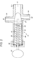
- FIGS 2 and 3 show in detail the actuator 21.
- This actuator comprises a cylinder body 30 having an axial orifice 31 provided in a connector 31a with a conduit 13b leading to the conduit 10, and two radial orifices 32, 33 diametrically opposite and provided in connectors 34, 35 with a conduit 13a leading to the control chamber 12 and the circuit 22.
- the end of the cylinder body 30 opposite the axial orifice 31 is closed by a knurled cover 36.
- a warhead 37 is slidably mounted in the internal cavity 38 of the cylinder body 30.
- the warhead 37 is integral with a rod 39 which passes through the cover 36 and which comprises, at its outer end, a lever 40.
- a tension spring 41 is fixed by one of its ends to the cover 36 and by the other end to the warhead 37.
- a cylindrical sealing membrane 42 is interposed between the warhead 37 and the cover 36.
- the conduits 13a and 13b constitute the second derivation 13 described above.
- the internal cavity 38 between the warhead 37 and the cover 36 is normally at atmospheric pressure.
- the warhead 37 can take two positions, a closed position shown in FIG. 2 in which the warhead closes the openings 31, 32 and 33 together, and an open or trigger position in which the warhead 37 is held on the side of the cover 36 by the tension spring 41, the orifices 31, 32 and 33 then communicating with one another.
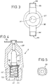
- FIGS 4 and 5 show a sprinkler 3 for installation 1 according to the invention.
- This sprinkler 3 has a connector 50 for fixing to the piping of the network 2, which has, in its center, an orifice 51 normally closed by a fuse 52, a bulb for example, bearing against a stirrup 53 secured to the connector 50, and a deflector 54 fixed on the stirrup 53 opposite the orifice 51.
- a flange 55 is mounted which serves to support a first end of a compression spring 56, the other of which end is supported on the underside of a cap 57 which normally closes the orifice 51 and which has, on its outer face, a support cradle 58 for the base of the bulb.
- the tightening of the fuse 52 compresses the cap 57 and the spring 56.
- the tension spring 41 of the actuator 21 is calibrated in such a way that, when the network 2 of sprinklers is in depression relative to atmospheric pressure, the depression existing in the conduit 13b can maintain the warhead 37 in the position of closing, and in such a way that, when the pressure in the duct 13b increases and approaches atmospheric pressure, due to a rupture of a fuse 52 of sprinkler, the warhead 37 moves towards the opening position under the action of the tension spring 41 and pressure differences between the orifice 31 and the cavity 38.
- the shut-off valve 8 is closed, the vacuum pump is started 11 and the warhead 37 is applied against the orifice 31 by pressing the lever 40
- the handle 40 is released and the valve 17 is opened for the pressure setting of the control chamber 12. Balancing in the valve 6 and the closure of the valve 14 will be done via the safety valve 60 and the calibrated orifice 18.
- the valve 6 is operational. All that remains is to open the shut-off valve 8.
- the pressure in the network 2 of sprinklers is less than atmospheric pressure by a value of approximately - 0.6 bar.
Landscapes
- Health & Medical Sciences (AREA)
- Public Health (AREA)
- Business, Economics & Management (AREA)
- Emergency Management (AREA)
- Fire-Extinguishing By Fire Departments, And Fire-Extinguishing Equipment And Control Thereof (AREA)
Applications Claiming Priority (2)
| Application Number | Priority Date | Filing Date | Title |
|---|---|---|---|
| FR9410892A FR2724323A1 (fr) | 1994-09-13 | 1994-09-13 | Installation de protection contre l'incendie |
| FR9410892 | 1994-09-13 |
Publications (2)
| Publication Number | Publication Date |
|---|---|
| EP0701841A1 true EP0701841A1 (de) | 1996-03-20 |
| EP0701841B1 EP0701841B1 (de) | 1999-12-22 |
Family
ID=9466881
Family Applications (1)
| Application Number | Title | Priority Date | Filing Date |
|---|---|---|---|
| EP19950402044 Expired - Lifetime EP0701841B1 (de) | 1994-09-13 | 1995-09-11 | Feuerschutzeinrichtung |
Country Status (5)
| Country | Link |
|---|---|
| EP (1) | EP0701841B1 (de) |
| AU (1) | AU695191B2 (de) |
| CA (1) | CA2158200C (de) |
| DE (1) | DE69514058T2 (de) |
| FR (1) | FR2724323A1 (de) |
Families Citing this family (4)
| Publication number | Priority date | Publication date | Assignee | Title |
|---|---|---|---|---|
| DE10208052C1 (de) * | 2002-02-25 | 2003-11-27 | Preussag Ag Minimax | Sprinkleranlage zum einfachen Wechseln von Sprinklern |
| FR3002163B1 (fr) * | 2013-02-21 | 2016-12-30 | Vactec | Restricteur de pression pneumatique dont l'ajutage secondaire est interchangeable, et installation de lutte contre les incendies correspondante |
| FR3002154B1 (fr) | 2013-02-21 | 2015-12-04 | Vactec | Installation de lutte contre les incendies, incluant un reseau de sprinklers sous vide, susceptibles d'etre declenches par un actuateur pilote par un actionneur maitre |
| FR3002150B1 (fr) | 2013-02-21 | 2018-03-16 | Vactec | Sprinkler comprenant un opercule d'obturation maintenu en position par un fusible a l'aide d'un moyen d'appui deplacable |
Citations (4)
| Publication number | Priority date | Publication date | Assignee | Title |
|---|---|---|---|---|
| US3759331A (en) | 1972-04-27 | 1973-09-18 | Factory Mutual Res Corp | Fire protection system utilizing dry pipes normally maintained in a vacuum |
| FR2225927A5 (en) * | 1973-04-13 | 1974-11-08 | Materiel Ind Projection | Remotely controlled fire extinguisher installation - has 3-way valve between fluid reservoir and discharge circuit |
| EP0209388A2 (de) * | 1985-07-18 | 1987-01-21 | Alan George William Dry | Berieselungsanlage mit trockenen Rohren |
| US5010959A (en) * | 1989-12-07 | 1991-04-30 | Automatic Sprinkler Corporation Of America | Automatic sprinkler head |
-
1994
- 1994-09-13 FR FR9410892A patent/FR2724323A1/fr active Granted
-
1995
- 1995-09-11 DE DE1995614058 patent/DE69514058T2/de not_active Expired - Lifetime
- 1995-09-11 EP EP19950402044 patent/EP0701841B1/de not_active Expired - Lifetime
- 1995-09-13 AU AU30640/95A patent/AU695191B2/en not_active Expired
- 1995-09-13 CA CA002158200A patent/CA2158200C/en not_active Expired - Lifetime
Patent Citations (4)
| Publication number | Priority date | Publication date | Assignee | Title |
|---|---|---|---|---|
| US3759331A (en) | 1972-04-27 | 1973-09-18 | Factory Mutual Res Corp | Fire protection system utilizing dry pipes normally maintained in a vacuum |
| FR2225927A5 (en) * | 1973-04-13 | 1974-11-08 | Materiel Ind Projection | Remotely controlled fire extinguisher installation - has 3-way valve between fluid reservoir and discharge circuit |
| EP0209388A2 (de) * | 1985-07-18 | 1987-01-21 | Alan George William Dry | Berieselungsanlage mit trockenen Rohren |
| US5010959A (en) * | 1989-12-07 | 1991-04-30 | Automatic Sprinkler Corporation Of America | Automatic sprinkler head |
Also Published As
| Publication number | Publication date |
|---|---|
| DE69514058T2 (de) | 2000-09-14 |
| CA2158200C (en) | 2007-01-02 |
| FR2724323A1 (fr) | 1996-03-15 |
| AU3064095A (en) | 1996-03-28 |
| AU695191B2 (en) | 1998-08-06 |
| DE69514058D1 (de) | 2000-01-27 |
| FR2724323B1 (de) | 1997-02-07 |
| CA2158200A1 (en) | 1996-03-14 |
| EP0701841B1 (de) | 1999-12-22 |
Similar Documents
| Publication | Publication Date | Title |
|---|---|---|
| CA2589115C (fr) | Systeme, notamment anti-feu, avec vannes | |
| EP0781950B1 (de) | Gaszuführungssystem für ein Verteilnetz | |
| US5927406A (en) | Fire protection installation involving a normally dry network of sprinklers | |
| FR2501511A1 (fr) | Appareil de protection respiratoire fonctionnant en circuit ferme, a commande electrique et mecanique | |
| EP1931959B1 (de) | Fluidströmungs-steuerventil | |
| EP0010465A2 (de) | Sich automatisch öffnendes Ventil, insbesondere für Feuerlöschanlagen | |
| CH419460A (fr) | Appareil de thérapie à oxygène sous pression | |
| EP0701841B1 (de) | Feuerschutzeinrichtung | |
| EP0451073B1 (de) | Vorrichtung zur hydraulischen Fernsteuerung eines Gerätes, insbesondere eines Hochdruckreinigers | |
| FR2681399A1 (fr) | Dispositif d'arret automatique et de securite destine notamment aux postes de detente de gaz. | |
| EP2958641B1 (de) | Brandbekämpfungsanlage mit einem netz aus vakuumsprinklern, auslösbar durch einen mittels eines membran-master-aktuators betriebenen aktuator | |
| WO1980002874A1 (fr) | Dispositif de mesure et de controle de debits gazeux | |
| FR2537689A1 (fr) | Vanne d'extincteur a pression de fluide permanente | |
| EP0743489B1 (de) | Gaszufuhreinrichtung, Vorrichtung zur Erzeugung einer Flamme die diese Einrichtung enthält und Druckminderer dafür | |
| WO1982000197A1 (fr) | Dispositif de mesure et de controle de debits gazeux | |
| FR2527804A1 (fr) | Dispositif d'arret d'emplissage de reservoir, notamment pour gaz de petrole liquefies | |
| EP0309633A1 (de) | Alarmsystem mit pneumatischer Steuerung für ein pneumatisches Beatmungsgerät | |
| FR2756390A1 (fr) | Appareil de regulation automatique de pression de gaz | |
| FR2757223A1 (fr) | Installation hydraulique a au moins un circuit d'utilisation du type a centre ferme | |
| FR2486234A1 (fr) | Dispositif de mesure et de controle de debits gazeux | |
| FR2458486A1 (fr) | Dispositif de securite de debit, pour un reservoir de stockage d'un liquide | |
| FR2582749A1 (fr) | Raccord-demarreur pour la mise en pression progressive des installations pneumatiques | |
| FR2495316A2 (fr) | Dispositif de mesure et de controle de debits gazeux | |
| WO1990002899A1 (fr) | Vanne haute pression utilisable notamment dans un outil de coupe a jet fluide | |
| FR2524602A1 (fr) | Dispositif d'arret automatique de remplissage de reservoir sous pression pour gaz de petrole liquefies et reservoir equipe d'un tel dispositif |
Legal Events
| Date | Code | Title | Description |
|---|---|---|---|
| PUAI | Public reference made under article 153(3) epc to a published international application that has entered the european phase |
Free format text: ORIGINAL CODE: 0009012 |
|
| AK | Designated contracting states |
Kind code of ref document: A1 Designated state(s): BE DE GB IT LU NL SE |
|
| 17P | Request for examination filed |
Effective date: 19960822 |
|
| 17Q | First examination report despatched |
Effective date: 19981009 |
|
| GRAG | Despatch of communication of intention to grant |
Free format text: ORIGINAL CODE: EPIDOS AGRA |
|
| GRAG | Despatch of communication of intention to grant |
Free format text: ORIGINAL CODE: EPIDOS AGRA |
|
| GRAH | Despatch of communication of intention to grant a patent |
Free format text: ORIGINAL CODE: EPIDOS IGRA |
|
| GRAH | Despatch of communication of intention to grant a patent |
Free format text: ORIGINAL CODE: EPIDOS IGRA |
|
| GRAA | (expected) grant |
Free format text: ORIGINAL CODE: 0009210 |
|
| AK | Designated contracting states |
Kind code of ref document: B1 Designated state(s): BE DE GB IT LU NL SE |
|
| PG25 | Lapsed in a contracting state [announced via postgrant information from national office to epo] |
Ref country code: SE Free format text: THE PATENT HAS BEEN ANNULLED BY A DECISION OF A NATIONAL AUTHORITY Effective date: 19991222 Ref country code: NL Free format text: LAPSE BECAUSE OF FAILURE TO SUBMIT A TRANSLATION OF THE DESCRIPTION OR TO PAY THE FEE WITHIN THE PRESCRIBED TIME-LIMIT Effective date: 19991222 Ref country code: IT Free format text: LAPSE BECAUSE OF FAILURE TO SUBMIT A TRANSLATION OF THE DESCRIPTION OR TO PAY THE FEE WITHIN THE PRE;WARNING: LAPSES OF ITALIAN PATENTS WITH EFFECTIVE DATE BEFORE 2007 MAY HAVE OCCURRED AT ANY TIME BEFORE 2007. THE CORRECT EFFECTIVE DATE MAY BE DIFFERENT FROM THE ONE RECORDED.SCRIBED TIME-LIMIT Effective date: 19991222 |
|
| REF | Corresponds to: |
Ref document number: 69514058 Country of ref document: DE Date of ref document: 20000127 |
|
| GBT | Gb: translation of ep patent filed (gb section 77(6)(a)/1977) |
Effective date: 20000303 |
|
| NLV1 | Nl: lapsed or annulled due to failure to fulfill the requirements of art. 29p and 29m of the patents act | ||
| PLBE | No opposition filed within time limit |
Free format text: ORIGINAL CODE: 0009261 |
|
| STAA | Information on the status of an ep patent application or granted ep patent |
Free format text: STATUS: NO OPPOSITION FILED WITHIN TIME LIMIT |
|
| 26N | No opposition filed | ||
| REG | Reference to a national code |
Ref country code: GB Ref legal event code: IF02 |
|
| PGFP | Annual fee paid to national office [announced via postgrant information from national office to epo] |
Ref country code: LU Payment date: 20140922 Year of fee payment: 20 Ref country code: DE Payment date: 20140911 Year of fee payment: 20 |
|
| PGFP | Annual fee paid to national office [announced via postgrant information from national office to epo] |
Ref country code: GB Payment date: 20140917 Year of fee payment: 20 |
|
| PGFP | Annual fee paid to national office [announced via postgrant information from national office to epo] |
Ref country code: BE Payment date: 20140929 Year of fee payment: 20 |
|
| REG | Reference to a national code |
Ref country code: DE Ref legal event code: R071 Ref document number: 69514058 Country of ref document: DE |
|
| REG | Reference to a national code |
Ref country code: GB Ref legal event code: PE20 Expiry date: 20150910 |
|
| PG25 | Lapsed in a contracting state [announced via postgrant information from national office to epo] |
Ref country code: GB Free format text: LAPSE BECAUSE OF EXPIRATION OF PROTECTION Effective date: 20150910 |