EP0701842A2 - Buse de pulvérisation pour l'atomisation de l'eau pour protection contre l'incendie - Google Patents
Buse de pulvérisation pour l'atomisation de l'eau pour protection contre l'incendie Download PDFInfo
- Publication number
- EP0701842A2 EP0701842A2 EP95114287A EP95114287A EP0701842A2 EP 0701842 A2 EP0701842 A2 EP 0701842A2 EP 95114287 A EP95114287 A EP 95114287A EP 95114287 A EP95114287 A EP 95114287A EP 0701842 A2 EP0701842 A2 EP 0701842A2
- Authority
- EP
- European Patent Office
- Prior art keywords
- spray nozzle
- nozzle according
- housing
- legs
- spray
- Prior art date
- Legal status (The legal status is an assumption and is not a legal conclusion. Google has not performed a legal analysis and makes no representation as to the accuracy of the status listed.)
- Granted
Links
Images


Classifications
-
- A—HUMAN NECESSITIES
- A62—LIFE-SAVING; FIRE-FIGHTING
- A62C—FIRE-FIGHTING
- A62C37/00—Control of fire-fighting equipment
- A62C37/08—Control of fire-fighting equipment comprising an outlet device containing a sensor, or itself being the sensor, i.e. self-contained sprinklers
Definitions
- the invention relates to a spray nozzle of the type mentioned in the preamble of claim 1 for atomizing water in fire protection systems.
- a spray nozzle of the type in question which has a swirl chamber in which there are narrow, helical channels that lead to a narrow, coaxial nozzle opening.
- the flowing water is set in rotation by the helical channels.
- the speed of rotation is increased considerably, so that the liquid is torn apart as a spray when exiting the nozzle opening by the then effective centrifugal forces.
- This known spray nozzle is used in such a way that several spray nozzles are connected via pipes to a common shut-off valve.
- the shut-off valve is connected to a water supply via a pipeline which is filled with pressurized water up to the shut-off valve.
- the nozzle openings of the spray nozzles are not closed.
- a hose line is provided which consists of a thermoplastic material and which is under a control pressure Water is filled.
- the control pressure is monitored by a pressure switch or the like, through which the shut-off valve can be controlled.
- the ambient temperature exceeds a predetermined temperature as a result of a fire, this leads to the hose line bursting and thus to a drop in the control pressure in the hose line, so that the shut-off valve opens.
- the pressurized water then flows through the pipelines to the spray nozzles and exits through the respective nozzle opening, a spray being formed in front of the spray nozzles in the manner described above.
- a disadvantage of the known spray nozzle is that the hose line, the pressure switch monitoring the control pressure in the hose line and the shut-off valve controlled by the pressure switch are complex and therefore expensive.
- the hose line must be routed through all areas at risk of fire, so that large quantities of hose are required to monitor large areas. This is expensive and complex when laying the hose line.
- temperature fluctuations in the long hose line can lead to a drop in pressure. If the control pressure in the hose line falls below a predetermined value, the shut-off valve opens without there being a fire to be fought. Even in the event of leaks that lead to water escaping from the hose line and a drop in the control pressure in the hose line, there is a risk of false triggering. Such false releases result in unnecessary water damage.
- spray nozzles Since several spray nozzles are connected to the same shut-off valve, spray nozzles are also used in a local fire put into operation that are located away from the fire site. This leads to unnecessary water damage.
- the nozzle opening of the spray nozzle is always open so that it can easily become dirty. This leads to an impairment of the function of the spray nozzle.
- Sprinkler nozzles are known, for example from DE-OS 25 39 703, in which a baffle plate is arranged at a distance in front of an outlet opening formed in a housing of the sprinkler nozzle and is connected to the housing of the sprinkler nozzle via retaining brackets.
- An essentially cylindrical bursting body is supported on an adjusting screw arranged centrally in the impact region, and its end facing the outlet opening holds a sealing body, which seals the outlet opening, in the sealing position.
- the supply lines are filled with water up to the sprinkler nozzles.
- the bursting body bursts when a triggering temperature is reached, so that the sealing body is pushed outward and a bundled water jet emerges from the outlet opening and hits the baffle plate arranged in the blasting area, which distributes the water jet laterally. This creates water drops that are of a size that is not optimal for fire fighting and often leads to unnecessary water damage.
- the invention has for its object to provide a spray nozzle of the type in question, which does not have the disadvantages mentioned, which is simple in construction and thus inexpensive to manufacture, by the for fire fighting non-optimal droplet sizes and false triggering, unnecessary water damage are avoided and can be restored in a simple and time-saving manner after a fire.
- the basic idea of the teaching according to the invention is to fundamentally start from a spray nozzle and thus to take advantage of the properties of the spray nozzle which are favorable with regard to fire fighting through a spray mist.
- the further idea of the invention is to modify the spray nozzle in such a way that each spray nozzle has a sealing body which seals the nozzle opening and is pressed against the housing by a pressure body which yields at a triggering temperature.
- the pipes can thus be filled with water under pressure up to the spray nozzles.
- the pressure element yields so that it no longer presses the sealing element against the housing.
- the sealing body is pressed outwards under the pressure of the water, so that the nozzle opening is released and the water emerges from the nozzle opening with the formation of a spray.
- Each spray nozzle can thus be put into operation separately from the others, so that in the event of a local fire, only those nozzles are put into operation in the vicinity of which the temperature exceeds a predetermined value due to the fire. Spray nozzles located away from the fire site are therefore not put into operation, so that unnecessary water damage is avoided.
- a hose line filled with water, a pressure switch and a shut-off valve that can be controlled by it are not required. Fire protection systems in which the spray nozzle according to the invention is used are thus simple in construction and therefore inexpensive to manufacture.
- sealing body seals the nozzle opening of the spray nozzle, contamination of the nozzle opening is reliably avoided. Since the sealing body lies against the housing from the outside, damage to the nozzle opening is avoided.
- the pressure body is supported on an adjusting screw. In this way, the force with which the pressure body presses the sealing body against the housing can be adjusted.
- the pressure body can also be supported on a spring, which of course must be dimensioned so that the nozzle does not open under all pressure conditions occurring in the feed line, but only in the event of a fire.
- the spring has the advantage of a simple design. It can also compensate for manufacturing tolerances.
- the pressure element is expediently spherical or conical at its end facing away from the nozzle opening for bearing against a preferably spherical indentation of the adjusting screw.
- the pressure element is centered on the spherical indentation of the set screw when the spray nozzle is assembled. The assembly is thus simplified.
- the shape and size of the pressure body can be selected within wide limits.
- the pressure element is expediently essentially cylindrical.
- the pressure body is expediently formed by a hollow body made of glass or the like, which is preferably at least partially filled with a liquid that expands or evaporates under the influence of heat Alcohol, is filled.
- the materials required for the production of the pressure body are inexpensive. Any liquids can be used.
- the temperature at which the pressure element yields can be set within wide limits by selecting liquids with suitable expansion properties.
- the part connected to the housing is expediently a bracket which extends away from the housing from the nozzle opening.
- the bracket can be designed as a narrow part, so that the bracket only causes a small spray shadow which does not significantly impair the extinguishing effect of the spray nozzle.
- the bracket can be formed in one piece with the housing. This embodiment is particularly simple and therefore inexpensive to manufacture.
- bracket is formed by flat struts, the radial cross section of which runs along the radial direction of propagation of the spray mist. In this embodiment, a remaining spray shadow caused by the bracket is further reduced.
- the pressure body is supported on a support part detachably connected to the housing.
- the support part can, for example, be held in a clamped manner on the housing.
- the sealing body can expediently have an annular groove on its side facing away from the nozzle opening, in which a sealing ring made of elastomeric material is arranged.
- This embodiment is simple and therefore inexpensive to manufacture.
- the pressure element expediently has, on its side facing away from the nozzle opening, a centering pin which is coaxial with the annular groove and which projects into the nozzle opening.
- the pressure body is supported on a support part detachably connected to the housing, that the support part is designed as a fork with two legs which are movable in the spreading direction, that the ends of the legs are radial in a rest position Reach behind the projections on the housing in a form-fitting manner that spring means are provided which pretension the legs in the expansion direction and that the legs have projections which engage behind the pressure element, in such a way that the legs are secured against spreading in the rest position.
- the legs of the supporting part which are pretensioned in the spreading direction, expand when the pressure element yields, so that the ends of the legs come free from the radial projections on the housing and the supporting part detaches from the housing, so that the area in front of the spray nozzle is free and thus any spray shadow is avoided.
- At least one of the legs of the support part is designed as a spring and thus forms the spring means.
- the legs are expediently made of spring steel. This embodiment is simple and inexpensive to manufacture.
- the projections of the legs are each formed by an inwardly extending tab, each having a recess through which the pressure body extends in the rest position.
- a further development of this embodiment provides that the tabs are arranged at a distance from one another in the rest position in the direction of the nozzle axis. In this way it is prevented that when the pressure element yields, remaining parts, for example remaining bursting pieces in the case of a bursting body, get stuck in the recesses in the tabs and prevent movement of the legs and thus spreading apart of the supporting part. In this way, the reliability of the spray nozzle is further improved.
- An expedient development of the aforementioned embodiment provides that at least one of the tabs has a nose facing the other tab to secure a distance between the tabs.
- the flap expediently forms a part with the leg.
- This embodiment is simple and therefore inexpensive to manufacture because the tab is not a separate part to be connected to the leg.
- the spring is designed as a leaf spring which preferably consists of one piece with the resilient legs. This embodiment is simple and inexpensive to manufacture.
- the recess can be closed or open on the side.
- a closed recess can be formed, for example, by a hole in the tab. If the recess is open at the side, the tab forms a hook that engages behind the pressure element.
- the embodiment with the recesses provides that the recesses are expanded on their side facing away from the pressure body when in contact with the pressure body, in particular form an elongated hole. Due to the elongated holes, the risk is further reduced that, when the pressure element yields, remaining parts of the pressure element get stuck in the recesses and prevent the tabs from moving away from one another.
- the projections on the housing can be formed by a collar.
- the legs of the support part engage behind the collar, so that the support part is held securely on the housing in the rest position.
- the collar has two radial recesses on its circumference, which are diametrically opposite and whose diametrical distance corresponds to the diametrical distance of the free ends of the legs in the rest position.
- the legs are first compressed and prestressed and secured against spreading out by inserting the pressure element.
- the support part is placed axially on the housing in the direction of the nozzle axis in a rotational position in which the ends of the legs are located in the region of the radial recesses of the collar.
- the support member is rotated 90 ° around the nozzle axis so that the ends of the legs engage behind the collar.
- the support member is secured to the housing in the manner of a bayonet lock, so that the assembly of the spray nozzle is simple.
- the contact surface for the ends of the legs on the collar is designed to widen conically towards the support part. Due to the conical contact surface, the loosening of the ends of the legs from the collar is further improved when the support part is spread apart.
- the pressure body can also be a body that melts when the triggering temperature is reached. This is not readily possible in the case of spray nozzles in which the part on which the pressure body is supported does not come loose from the housing with the pressure body, because water emerging from the nozzle opening cools the body, so that the melting process is interrupted and the themselves near the Pressure element located in the nozzle opening impedes the spreading of the spray.
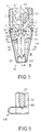
- the spray nozzle shown in Fig. 1 has a housing 1 with an external thread 2 for screwing the nozzle into a feed line, not shown.
- the housing 1 has a cylindrical inner wall 3 which merges into a conical inner wall 4 and opens into a nozzle opening 5.
- the end 6 of the cylindrical inner wall 3 facing away from the nozzle opening 5 is provided with an internal thread 7 into which a nozzle part 8 is screwed in with an external thread 9.
- the nozzle part 8 has at its end 10 facing away from the nozzle opening 5 a supply opening 11 through which water is supplied from the supply line to the spray nozzle.
- the nozzle part 8 has narrow, helical channels 12 on its outside, and a swirl chamber 13 is formed between the nozzle part 8 and the cylindrical inner wall 3 or the conical inner wall 4, which is connected to the nozzle opening 5.
- a bracket 15, which extends from the housing 1 away from the nozzle opening 5, is attached to an annular region 14 of the housing 1 coaxial with the nozzle opening 5, with an annular region 16 formed at its end facing the housing 1 and by screws, of which only one screw 17 is shown as an example, releasably connected to the housing 1.
- the nozzle opening 5 is closed by a sealing body which has a sealing sleeve 18 and a sealing ring 20 made of elastomeric material which is arranged in an annular groove 19 which is formed on the side of the sealing sleeve 18 facing the nozzle opening 5 having.
- the sealing sleeve 18 On its side facing the nozzle opening 5, the sealing sleeve 18 has a centering pin 21 which is coaxial with the annular groove 19 and extends into the nozzle opening 5.
- the sealing sleeve 18 On its side facing away from the nozzle opening 5, the sealing sleeve 18 has a central bore 22 which widens away from the nozzle opening 5 into an essentially conical area 23 in which a contact surface 24 for a pressure element 25 is formed.
- the pressure body 25 is formed by a hollow body made of glass filled with alcohol.
- the end of the pressure element 25 facing the nozzle opening 11 is essentially conical and lies against the contact surface 24 of the sealing sleeve 18.
- the end of the pressure element 25 facing away from the nozzle opening 5 is spherical.
- the end 29 facing the pressure body 25 has a spherical indentation 30 for abutment against the spherical end of the pressure body 25, the pressure body 23 and the sealing body can be biased in the direction of the nozzle opening 5.
- bracket 15 is narrow, so that a spray can form in the operating state of the spray nozzle, which extends over a wide range of the circumference of the spray nozzle. It is thus caused by the bracket 15 only a small spray shadow, which does not significantly affect the extinguishing effect of the spray nozzle.
- the spray generated in this way is well suited for fighting a fire due to its small droplet size, but only those in a fire Spray nozzles are put into operation, in the vicinity of which the temperature has exceeded the specified value as a result of a fire. Unnecessary water damage is thus reliably avoided.
- FIG. 4 shows a second exemplary embodiment of the spray nozzle according to the invention, which has a support part 33 designed as a fork with two legs 31, 32.
- the free ends of the legs 31, 32 are designed as hooks 34, 35, which positively engage behind a projection on the housing 1 formed by a collar 36.
- a contact surface 37 for the hooks 34, 35 on the collar 36 is designed to widen conically towards the support part 33.
- the support part 33 is designed to be expandable, and the legs 31, 32 are each movable in the direction of an arrow 38, 39, which symbolizes the direction of expansion.
- the legs 31, 32 are made of spring steel and thus form spring means that pretension the legs 31, 32 in the expanded position in the rest position shown in FIG. 4.
- the legs 31, 32 each have an inwardly directed tab 40, 41, each of which has a recess in the embodiment shown in FIG. 4 as an elongated hole 42, 43.
- the tabs 40, 41 are arranged approximately parallel to one another.
- the tab 41 has at its free end a nose 44 facing the other tab 40, which ensures that the tabs 40, 41 are arranged at a distance from one another in the direction of the nozzle axis symbolized by a dash-dotted line 45.
- the pressure body 25 In the rest position shown in FIG. 4, the pressure body 25 is supported with its end facing away from the nozzle opening 5 on the set screw 28 of the supporting part 33 and presses the sealing disk 20 against the housing 1 via the sealing sleeve 18 with its end facing the nozzle opening 5, so that the nozzle opening 5 is tightly closed in the idle state.
- the pressure body 25 extends through the elongated holes 42, 43 of the tabs 40, 41, which thus the pressure body 25 reach behind, so that the legs 31, 32 are secured against spreading in the rest position.
- Fig. 5 shows a view from below in Fig. 4 of the spray nozzle.
- the collar 36 has on its circumference two radial recesses formed by flats 47, 48 in this embodiment, which are diametrically opposite and whose diametrical distance corresponds to the diametrical distance of the free ends of the legs 31, 32 designed as hooks 35, 36 .
- the legs 31, 32 of the support part 33 are compressed and biased in this way. Then the pressure body 25 is inserted from the free ends of the legs 31, 32 through the elongated holes 42, 43 until its end facing the set screw 28 comes to rest on the set screw 28.
- the support part 33 with the pressure element 25 inserted is placed axially onto the housing 1 in a rotational position in which the hooks 34, 35 are located in the area of the flats 47, 48.
- the support member 33 is rotated on the housing 1 about the nozzle axis 45 by about 90 °, so that the hooks 34, 35 engage behind the collar 36 of the housing 1.
- the support member 33 is secured to the housing 1 in the manner of a bayonet catch, so that the assembly of the spray nozzle according to the invention is particularly simple during manufacture or when a fire is restored.
- Fig. 6 shows a side view of the spray nozzle in the rest position.
- the recesses in the tabs 40, 41 are formed as elongated holes 42, 43 and by the distance in the direction of the nozzle axis of the tabs 40, 41 from each other it is ensured that the movement of the legs 31, 32 and thus the spreading of the support member 33rd is not hindered by remaining parts of the pressure body 25.
- FIG. 8 shows a third exemplary embodiment of the spray nozzle according to the invention, which differs from the exemplary embodiment according to FIG. 4 in that the pressure body 25 is not supported on an adjusting screw but on a spring, which in this exemplary embodiment is formed by a leaf spring 49 is, which is formed with the resilient legs 31, 32 in one piece.
- the leaf spring 49 biases the pressure body 25 in the direction of the nozzle opening 5; their spring force is such that the spray nozzle under all pressure conditions does not open in the feed line, but only in the event of a fire.
- the leaf spring also compensates for 49 manufacturing tolerances.
- the pressure body 25 projects with its end facing away from the nozzle opening 11 into a recess 50 formed in the region of the free end of the leaf spring 49.
- FIG. 9 shows a section IX-IX in FIG. 8. It can be seen that the leaf spring 49 with the legs 31, 32 consists of one piece and, in the rest state of the spray nozzle shown in FIG. 9, is bent with its free end in the direction of the nozzle opening 5 such that a part facing the nozzle opening 5 the leaf spring 49, in which the recess 50 is formed, is arranged at a distance from and approximately parallel to a part facing away from the nozzle opening 5.
Landscapes
- Health & Medical Sciences (AREA)
- Public Health (AREA)
- Business, Economics & Management (AREA)
- Emergency Management (AREA)
- Nozzles (AREA)
- Fire-Extinguishing By Fire Departments, And Fire-Extinguishing Equipment And Control Thereof (AREA)
Applications Claiming Priority (2)
| Application Number | Priority Date | Filing Date | Title |
|---|---|---|---|
| DE4433157 | 1994-09-17 | ||
| DE4433157 | 1994-09-17 |
Publications (4)
| Publication Number | Publication Date |
|---|---|
| EP0701842A2 true EP0701842A2 (fr) | 1996-03-20 |
| EP0701842A3 EP0701842A3 (fr) | 1997-04-09 |
| EP0701842B1 EP0701842B1 (fr) | 2001-04-04 |
| EP0701842B2 EP0701842B2 (fr) | 2004-11-03 |
Family
ID=6528471
Family Applications (1)
| Application Number | Title | Priority Date | Filing Date |
|---|---|---|---|
| EP95114287A Expired - Lifetime EP0701842B2 (fr) | 1994-09-17 | 1995-09-12 | Buse de pulvérisation pour l'atomisation de l'eau pour protection contre l'incendie |
Country Status (4)
| Country | Link |
|---|---|
| US (1) | US5667017A (fr) |
| EP (1) | EP0701842B2 (fr) |
| AT (1) | ATE200227T1 (fr) |
| DE (2) | DE59509153D1 (fr) |
Cited By (6)
| Publication number | Priority date | Publication date | Assignee | Title |
|---|---|---|---|---|
| RU2159649C1 (ru) * | 2000-03-28 | 2000-11-27 | Общество с ограниченной ответственностью "ЮНИПАТ" | Спринклер (варианты) |
| WO2005107880A1 (fr) | 2004-05-11 | 2005-11-17 | Andrey Leonidovich Dushkin | Procede et pulverisateur |
| RU2403927C2 (ru) * | 2008-10-17 | 2010-11-20 | Федеральное государственное учреждение Всероссийский ордена "Знак Почета" научно-исследовательский институт противопожарной обороны МЧС России (ФГУ ВНИИПО МЧС России) | Способ тушения пожара распыленной водой с добавками |
| RU2557517C1 (ru) * | 2014-04-10 | 2015-07-20 | Федеральное государственное бюджетное образовательное учреждение высшего профессионального образования "Национальный исследовательский Томский политехнический университет" | Способ тушения пожаров |
| RU2630786C1 (ru) * | 2016-03-18 | 2017-09-13 | Татьяна Дмитриевна Ходакова | Устройство пожаротушения со спринклерными оросителями |
| RU2647027C1 (ru) * | 2017-02-20 | 2018-03-13 | Олег Савельевич Кочетов | Спринклер |
Families Citing this family (18)
| Publication number | Priority date | Publication date | Assignee | Title |
|---|---|---|---|---|
| DE19711808A1 (de) * | 1997-03-21 | 1998-09-24 | Hans Joachim Herzog | Anreger-Wassernebel-Düse |
| US6102127A (en) * | 1997-12-12 | 2000-08-15 | Pierce; Lauvon | Temperature controlled valve for drip valves and sprinkler systems |
| DE19812994B4 (de) * | 1998-03-25 | 2005-10-06 | Ulrich Ziller | Bauteil-Feuerschutzeinrichtung |
| US6105678A (en) * | 1998-11-17 | 2000-08-22 | Shie Yu Machine Parts Industrial Co., Ltd. | Heat responsive fire extinguishing assembly for a ventilating duct |
| US6308784B1 (en) * | 2000-03-07 | 2001-10-30 | Grinnell Corporation | Flush sprinkler |
| DE10048544B4 (de) * | 2000-09-30 | 2004-04-22 | Minimax Gmbh | Stationäre Feuerlöschanlage mit kombinierter Anrege- und Löschleitung |
| US6554077B2 (en) | 2001-04-12 | 2003-04-29 | The Reliable Automatic Sprinkler Co., Inc. | Quick response adjustable automatic sprinkler arrangements |
| US6669111B2 (en) * | 2002-03-14 | 2003-12-30 | Polymer Molding, Inc. | Protector for thermally responsive member of sprinkler head |
| DE102004027568B3 (de) * | 2004-06-05 | 2005-12-08 | Minimax Gmbh & Co. Kg | Verfahren und Vorrichtung zum Einstellen einer definierten Dichtkraft eines Sprinklers für Feuerlöschanlagen |
| DE102005001717A1 (de) * | 2005-01-13 | 2006-07-27 | Höhne, Robert | Dralldüse für Brandbekämpfungsanlagen und Sprühdüse mit Auslösevorrichtung |
| US7878419B2 (en) * | 2006-09-19 | 2011-02-01 | Sta-Rite Industries, Llc | Spray head with covers |
| US7900852B2 (en) * | 2008-09-09 | 2011-03-08 | The Viking Corporation | Cover for protecting a fusible linkage in a sprinkler head |
| DE202009014429U1 (de) | 2009-10-26 | 2010-03-18 | Herzog, Ilse Dora | Vorrichtung zur Brandbekämpfung mittels Wassernebel |
| DE202009014428U1 (de) | 2009-10-26 | 2010-03-11 | Herzog, Ilse Dora | Vorrichtung zur Brandbekämpfung mittels Wassernebel |
| US9821126B2 (en) * | 2014-02-21 | 2017-11-21 | Neogen Corporation | Fluid atomizer, nozzle assembly and methods for assembling and utilizing the same |
| US10919066B2 (en) | 2018-06-08 | 2021-02-16 | The Reliable Automatic Sprinkler Co. Inc. | Sprinkler guard and a method of manufacturing a sprinkler guard |
| DE202022001722U1 (de) | 2022-08-02 | 2022-09-22 | Geo Vernebelungstechnik Gmbh | Vorrichtung zur Brandbekämpfung mittels Wasserverdüsung |
| GB2644076A (en) * | 2024-09-16 | 2026-03-18 | I Mist Holdings Ltd | Nozzle for water-based fire suppression system |
Family Cites Families (22)
| Publication number | Priority date | Publication date | Assignee | Title |
|---|---|---|---|---|
| CA648027A (en) * | 1962-09-04 | Allen George | Automatic sprinkler systems | |
| US2511945A (en) * | 1950-06-20 | Spray nozzle | ||
| DE207663C (fr) * | ||||
| US1608515A (en) * | 1923-09-07 | 1926-11-30 | Lowe Ernest Franklin | Automatic sprinkler |
| GB333412A (en) * | 1929-08-28 | 1930-08-14 | Cecil Henry Whittington | Improvements in automatic sprinklers for fire extinguishing purposes |
| GB885421A (en) * | 1959-05-27 | 1961-12-28 | Matthew Hall & Co Ltd | Improvements in or relating to automatic sprinkler systems |
| DE1559693A1 (de) * | 1966-10-27 | 1970-01-22 | Walther & Cie Ag | Durch Temperaturanstieg loesbare Seilverbindung fuer die Freigabe eines Loeschmittels od.dgl. in Feuerschutzanlagen |
| US3757866A (en) † | 1971-11-08 | 1973-09-11 | Grinnell Corp | On-off sprinkler |
| US3831682A (en) * | 1973-01-19 | 1974-08-27 | Rockwell Mfg Co | Fire extinguishing system nozzle |
| US3818994A (en) * | 1973-06-07 | 1974-06-25 | Factory Mutual Res Corp | Discharge head having a magnetic plug retaining assembly |
| DE2539703C2 (de) * | 1975-09-06 | 1982-07-29 | Eduard J. Ing.(grad.) 2070 Ahrensberg Job | Feuerlöschbrausekopf für selbsttätige Feuerlöschanlagen |
| CH597921A5 (fr) * | 1976-01-30 | 1978-04-14 | Jomos Sprinkler Material Ag | |
| DE7815775U1 (de) * | 1978-05-26 | 1978-11-23 | G.H. Zimmermann Gmbh, 6301 Dorlar | Zerstaeubungsduese |
| GB2076652B (en) * | 1980-05-10 | 1983-09-28 | Firemaster Extinguisher Ltd | Fire extinguisher discharge head |
| DD207663B1 (de) * | 1982-06-14 | 1987-05-13 | Herzog Hans Joachim | Anregeduese |
| DK148075C (da) * | 1982-12-07 | 1985-07-29 | Gw Sprinkler As | Sprinklerenhed |
| AU3263684A (en) * | 1983-09-01 | 1985-03-07 | Globe Fire Equipment Co. | Sprinkler head |
| USH121H (en) * | 1985-04-11 | 1986-09-02 | Central Sprinkler Corporation | Quick release valve for sprinkler head |
| US4739835A (en) * | 1986-06-23 | 1988-04-26 | Central Sprinkler Corp. | Quick response glass bulb sprinkler |
| DE3808384C2 (de) * | 1987-07-06 | 1990-03-22 | Total Feuerschutz Gmbh | Ausl¦seglied zur thermischen und/oder elektrischen Ausl¦sung einer Brandschutzanlage |
| DE3814043A1 (de) * | 1988-04-26 | 1989-11-09 | Krantz H Gmbh & Co | Feuerloeschanlage |
| JPH074826Y2 (ja) * | 1990-06-22 | 1995-02-08 | 孝正 服部 | スプリンクラーヘッド |
-
1995
- 1995-09-11 US US08/526,450 patent/US5667017A/en not_active Expired - Fee Related
- 1995-09-12 AT AT95114287T patent/ATE200227T1/de not_active IP Right Cessation
- 1995-09-12 EP EP95114287A patent/EP0701842B2/fr not_active Expired - Lifetime
- 1995-09-12 DE DE59509153T patent/DE59509153D1/de not_active Expired - Fee Related
- 1995-09-12 DE DE19533636A patent/DE19533636B4/de not_active Expired - Fee Related
Cited By (10)
| Publication number | Priority date | Publication date | Assignee | Title |
|---|---|---|---|---|
| RU2159649C1 (ru) * | 2000-03-28 | 2000-11-27 | Общество с ограниченной ответственностью "ЮНИПАТ" | Спринклер (варианты) |
| WO2001072375A1 (fr) | 2000-03-28 | 2001-10-04 | Obschestvo S Ogranichennoi Otvetstvennostiju 'unipat' | Gicleurs de type sprinkler |
| AU2000263289B2 (en) * | 2000-03-28 | 2004-11-18 | Obschestvo S Ogranichennoi Otvetstvennostju "Unipat" | Sprinklers |
| EP1488830A1 (fr) | 2000-03-28 | 2004-12-22 | Obschestvo S Ogranichennoi Otvetstvennostju "Unipat" | Arroseur |
| KR100520289B1 (ko) * | 2000-03-28 | 2005-10-13 | 오브스케스티보 에스 오그라니케노이 오트베츠베노츠주 "유니펫" | 스프링클러 |
| WO2005107880A1 (fr) | 2004-05-11 | 2005-11-17 | Andrey Leonidovich Dushkin | Procede et pulverisateur |
| RU2403927C2 (ru) * | 2008-10-17 | 2010-11-20 | Федеральное государственное учреждение Всероссийский ордена "Знак Почета" научно-исследовательский институт противопожарной обороны МЧС России (ФГУ ВНИИПО МЧС России) | Способ тушения пожара распыленной водой с добавками |
| RU2557517C1 (ru) * | 2014-04-10 | 2015-07-20 | Федеральное государственное бюджетное образовательное учреждение высшего профессионального образования "Национальный исследовательский Томский политехнический университет" | Способ тушения пожаров |
| RU2630786C1 (ru) * | 2016-03-18 | 2017-09-13 | Татьяна Дмитриевна Ходакова | Устройство пожаротушения со спринклерными оросителями |
| RU2647027C1 (ru) * | 2017-02-20 | 2018-03-13 | Олег Савельевич Кочетов | Спринклер |
Also Published As
| Publication number | Publication date |
|---|---|
| US5667017A (en) | 1997-09-16 |
| EP0701842B2 (fr) | 2004-11-03 |
| EP0701842B1 (fr) | 2001-04-04 |
| DE19533636A1 (de) | 1996-03-21 |
| DE19533636B4 (de) | 2005-11-10 |
| ATE200227T1 (de) | 2001-04-15 |
| DE59509153D1 (de) | 2001-05-10 |
| EP0701842A3 (fr) | 1997-04-09 |
Similar Documents
| Publication | Publication Date | Title |
|---|---|---|
| EP0701842A2 (fr) | Buse de pulvérisation pour l'atomisation de l'eau pour protection contre l'incendie | |
| DE69319915T2 (de) | Düse mit einer die flüssigkeit zum verwirbeln bringenden schraubenfeder | |
| DE4480591C2 (de) | Feuerschutzdüse | |
| DE3624939C2 (fr) | ||
| DE2728887A1 (de) | Anschlussvorrichtung | |
| DE102007054673B4 (de) | Bandschmiereinrichtung und/oder Reinigungs-Desinfektionsanlage | |
| EP3967409A1 (fr) | Élément étanche permettant d'étanchéifier une transition entre un corps de base d'un pistolet pulvérisateur et une pièce rapportée d'un pistolet pulvérisateur, pièce rapportée, en particulier agencement de buse de peinture, pour un pistolet pulvérisateur et pistolet pulvérisateur | |
| WO1996033775A1 (fr) | Dispositif extincteur a fluide extincteur | |
| DE20103812U1 (de) | Dralldüse zur Erzeugung von Sprühnebel | |
| DE2630519A1 (de) | Duese fuer halon-feuerloeschgeraete | |
| DE19608165C1 (de) | Thermische Armaturensicherung zum automatischen Absperren von Leitungen | |
| DE29709965U1 (de) | Thermisch betätigbares Sicherheitsventil | |
| WO2006074648A1 (fr) | Buse de pulverisation et buse a effet giratoire pour installations de lutte contre l'incendie et dispositif de declenchement associe actionnable en fonction de la temperature | |
| DE3327985A1 (de) | Geraet zur bekaempfung von brandherden im innern von gelagerten stoffen | |
| DE2239689C3 (de) | Spritzkopf für eine ortsfeste Feuerlöschanlage | |
| EP2915565B1 (fr) | Déclencheur pour une installation de lutte contre l'incendie | |
| DE3833279A1 (de) | Brennstoffduese fuer gasturbinen | |
| DE2049504B2 (de) | Ortsfeste Feuerlöschanlage mit einer Vielzahl von an eine Löschmittelquelle angeschlossenen Spritzköpfen | |
| DE10010876B4 (de) | Sprinkler mit Auswurfeinrichtung | |
| EP4309746B1 (fr) | Buse de lutte contre l'incendie, système de lutte contre l'incendie et procédé de fonctionnement d'un système de lutte contre l'incendie | |
| DE2243992A1 (de) | Abgabe- oder spritzkopf | |
| DE9409359U1 (de) | Feuerlöscher | |
| DE19711808A1 (de) | Anreger-Wassernebel-Düse | |
| DE19837146B4 (de) | Brandschutzeinsatz für gasführende Rohrdurchgänge | |
| DE202007003854U1 (de) | Düsenhalter |
Legal Events
| Date | Code | Title | Description |
|---|---|---|---|
| PUAI | Public reference made under article 153(3) epc to a published international application that has entered the european phase |
Free format text: ORIGINAL CODE: 0009012 |
|
| AK | Designated contracting states |
Kind code of ref document: A2 Designated state(s): AT BE CH DE DK FR GB IT LI NL SE |
|
| RBV | Designated contracting states (corrected) |
Designated state(s): AT BE CH DE DK ES FR GB GR IE IT LI LU MC NL PT SE |
|
| PUAL | Search report despatched |
Free format text: ORIGINAL CODE: 0009013 |
|
| AK | Designated contracting states |
Kind code of ref document: A3 Designated state(s): AT BE CH DE DK ES FR GB GR IE IT LI LU MC NL PT SE |
|
| RBV | Designated contracting states (corrected) |
Designated state(s): AT BE CH DE DK FR GB IT LI NL SE |
|
| 17P | Request for examination filed |
Effective date: 19970523 |
|
| 17Q | First examination report despatched |
Effective date: 19981022 |
|
| RAP1 | Party data changed (applicant data changed or rights of an application transferred) |
Owner name: MINIMAX GMBH |
|
| GRAG | Despatch of communication of intention to grant |
Free format text: ORIGINAL CODE: EPIDOS AGRA |
|
| GRAG | Despatch of communication of intention to grant |
Free format text: ORIGINAL CODE: EPIDOS AGRA |
|
| GRAH | Despatch of communication of intention to grant a patent |
Free format text: ORIGINAL CODE: EPIDOS IGRA |
|
| GRAH | Despatch of communication of intention to grant a patent |
Free format text: ORIGINAL CODE: EPIDOS IGRA |
|
| GRAA | (expected) grant |
Free format text: ORIGINAL CODE: 0009210 |
|
| AK | Designated contracting states |
Kind code of ref document: B1 Designated state(s): AT BE CH DE DK FR GB IT LI NL SE |
|
| PG25 | Lapsed in a contracting state [announced via postgrant information from national office to epo] |
Ref country code: NL Free format text: LAPSE BECAUSE OF FAILURE TO SUBMIT A TRANSLATION OF THE DESCRIPTION OR TO PAY THE FEE WITHIN THE PRESCRIBED TIME-LIMIT Effective date: 20010404 Ref country code: IT Free format text: LAPSE BECAUSE OF FAILURE TO SUBMIT A TRANSLATION OF THE DESCRIPTION OR TO PAY THE FEE WITHIN THE PRESCRIBED TIME-LIMIT;WARNING: LAPSES OF ITALIAN PATENTS WITH EFFECTIVE DATE BEFORE 2007 MAY HAVE OCCURRED AT ANY TIME BEFORE 2007. THE CORRECT EFFECTIVE DATE MAY BE DIFFERENT FROM THE ONE RECORDED. Effective date: 20010404 Ref country code: GB Free format text: LAPSE BECAUSE OF FAILURE TO SUBMIT A TRANSLATION OF THE DESCRIPTION OR TO PAY THE FEE WITHIN THE PRESCRIBED TIME-LIMIT Effective date: 20010404 Ref country code: FR Free format text: LAPSE BECAUSE OF FAILURE TO SUBMIT A TRANSLATION OF THE DESCRIPTION OR TO PAY THE FEE WITHIN THE PRESCRIBED TIME-LIMIT Effective date: 20010404 |
|
| REF | Corresponds to: |
Ref document number: 200227 Country of ref document: AT Date of ref document: 20010415 Kind code of ref document: T |
|
| REG | Reference to a national code |
Ref country code: CH Ref legal event code: EP |
|
| REF | Corresponds to: |
Ref document number: 59509153 Country of ref document: DE Date of ref document: 20010510 |
|
| PG25 | Lapsed in a contracting state [announced via postgrant information from national office to epo] |
Ref country code: SE Free format text: LAPSE BECAUSE OF FAILURE TO SUBMIT A TRANSLATION OF THE DESCRIPTION OR TO PAY THE FEE WITHIN THE PRESCRIBED TIME-LIMIT Effective date: 20010704 |
|
| EN | Fr: translation not filed | ||
| NLV1 | Nl: lapsed or annulled due to failure to fulfill the requirements of art. 29p and 29m of the patents act | ||
| PG25 | Lapsed in a contracting state [announced via postgrant information from national office to epo] |
Ref country code: BE Free format text: LAPSE BECAUSE OF NON-PAYMENT OF DUE FEES Effective date: 20010930 |
|
| GBV | Gb: ep patent (uk) treated as always having been void in accordance with gb section 77(7)/1977 [no translation filed] |
Effective date: 20010404 |
|
| PG25 | Lapsed in a contracting state [announced via postgrant information from national office to epo] |
Ref country code: DK Free format text: LAPSE BECAUSE OF FAILURE TO SUBMIT A TRANSLATION OF THE DESCRIPTION OR TO PAY THE FEE WITHIN THE PRESCRIBED TIME-LIMIT Effective date: 20011011 |
|
| PLBQ | Unpublished change to opponent data |
Free format text: ORIGINAL CODE: EPIDOS OPPO |
|
| PLBI | Opposition filed |
Free format text: ORIGINAL CODE: 0009260 |
|
| PLBQ | Unpublished change to opponent data |
Free format text: ORIGINAL CODE: EPIDOS OPPO |
|
| PLBI | Opposition filed |
Free format text: ORIGINAL CODE: 0009260 |
|
| 26 | Opposition filed |
Opponent name: TOTAL WALTHER GMBH, FEUERSCHUTZ UND SICHERHEIT Effective date: 20011204 |
|
| PLBF | Reply of patent proprietor to notice(s) of opposition |
Free format text: ORIGINAL CODE: EPIDOS OBSO |
|
| 26 | Opposition filed |
Opponent name: SYSTEMTECHNIK HERZOG GMBH Effective date: 20011221 Opponent name: TOTAL WALTHER GMBH, FEUERSCHUTZ UND SICHERHEIT Effective date: 20011204 |
|
| BERE | Be: lapsed |
Owner name: MINIMAX G.M.B.H. Effective date: 20010930 |
|
| PLBF | Reply of patent proprietor to notice(s) of opposition |
Free format text: ORIGINAL CODE: EPIDOS OBSO |
|
| PGFP | Annual fee paid to national office [announced via postgrant information from national office to epo] |
Ref country code: AT Payment date: 20040810 Year of fee payment: 10 |
|
| PGFP | Annual fee paid to national office [announced via postgrant information from national office to epo] |
Ref country code: CH Payment date: 20040818 Year of fee payment: 10 |
|
| PUAH | Patent maintained in amended form |
Free format text: ORIGINAL CODE: 0009272 |
|
| STAA | Information on the status of an ep patent application or granted ep patent |
Free format text: STATUS: PATENT MAINTAINED AS AMENDED |
|
| RAP2 | Party data changed (patent owner data changed or rights of a patent transferred) |
Owner name: MINIMAX GMBH & CO KG |
|
| 27A | Patent maintained in amended form |
Effective date: 20041103 |
|
| AK | Designated contracting states |
Kind code of ref document: B2 Designated state(s): AT BE CH DE DK FR GB IT LI NL SE |
|
| REG | Reference to a national code |
Ref country code: CH Ref legal event code: AEN Free format text: AUFRECHTERHALTUNG DES PATENTES IN GEAENDERTER FORM |
|
| PG25 | Lapsed in a contracting state [announced via postgrant information from national office to epo] |
Ref country code: AT Free format text: LAPSE BECAUSE OF NON-PAYMENT OF DUE FEES Effective date: 20050912 |
|
| PG25 | Lapsed in a contracting state [announced via postgrant information from national office to epo] |
Ref country code: LI Free format text: LAPSE BECAUSE OF NON-PAYMENT OF DUE FEES Effective date: 20050930 Ref country code: CH Free format text: LAPSE BECAUSE OF NON-PAYMENT OF DUE FEES Effective date: 20050930 |
|
| EN | Fr: translation not filed | ||
| REG | Reference to a national code |
Ref country code: CH Ref legal event code: PL |
|
| PGFP | Annual fee paid to national office [announced via postgrant information from national office to epo] |
Ref country code: DE Payment date: 20060815 Year of fee payment: 12 |
|
| PG25 | Lapsed in a contracting state [announced via postgrant information from national office to epo] |
Ref country code: DE Free format text: LAPSE BECAUSE OF NON-PAYMENT OF DUE FEES Effective date: 20080401 |
|
| PLAB | Opposition data, opponent's data or that of the opponent's representative modified |
Free format text: ORIGINAL CODE: 0009299OPPO |
|
| R26 | Opposition filed (corrected) |
Opponent name: SYSTEMTECHNIK HERZOG GMBH Effective date: 20011221 Opponent name: TOTAL WALTHER GMBH, FEUERSCHUTZ UND SICHERHEIT Effective date: 20011204 |