EP0701849B1 - Spielvorrichtung mit einem Körper dessen Bewegung ein Ergebnis eines Spieles bestimmt - Google Patents
Spielvorrichtung mit einem Körper dessen Bewegung ein Ergebnis eines Spieles bestimmt Download PDFInfo
- Publication number
- EP0701849B1 EP0701849B1 EP95306429A EP95306429A EP0701849B1 EP 0701849 B1 EP0701849 B1 EP 0701849B1 EP 95306429 A EP95306429 A EP 95306429A EP 95306429 A EP95306429 A EP 95306429A EP 0701849 B1 EP0701849 B1 EP 0701849B1
- Authority
- EP
- European Patent Office
- Prior art keywords
- dice
- field
- game
- game apparatus
- throwing
- Prior art date
- Legal status (The legal status is an assumption and is not a legal conclusion. Google has not performed a legal analysis and makes no representation as to the accuracy of the status listed.)
- Expired - Lifetime
Links
- 230000033001 locomotion Effects 0.000 title claims description 16
- 230000007246 mechanism Effects 0.000 claims description 124
- 239000000843 powder Substances 0.000 claims description 36
- 238000000034 method Methods 0.000 claims description 11
- 230000004044 response Effects 0.000 claims description 9
- 230000008569 process Effects 0.000 claims description 7
- 230000009471 action Effects 0.000 claims description 5
- 230000005540 biological transmission Effects 0.000 claims description 4
- 230000001419 dependent effect Effects 0.000 claims description 4
- 238000001514 detection method Methods 0.000 description 13
- 230000003287 optical effect Effects 0.000 description 13
- 238000005286 illumination Methods 0.000 description 11
- 238000004891 communication Methods 0.000 description 10
- 238000003825 pressing Methods 0.000 description 7
- 238000005096 rolling process Methods 0.000 description 7
- 238000010586 diagram Methods 0.000 description 4
- 238000004364 calculation method Methods 0.000 description 3
- 238000012423 maintenance Methods 0.000 description 3
- 238000012545 processing Methods 0.000 description 3
- 230000008901 benefit Effects 0.000 description 2
- 230000008451 emotion Effects 0.000 description 2
- 230000005415 magnetization Effects 0.000 description 2
- 208000024827 Alzheimer disease Diseases 0.000 description 1
- 206010039966 Senile dementia Diseases 0.000 description 1
- 230000003213 activating effect Effects 0.000 description 1
- 230000008859 change Effects 0.000 description 1
- 238000006243 chemical reaction Methods 0.000 description 1
- 238000010276 construction Methods 0.000 description 1
- 238000005034 decoration Methods 0.000 description 1
- 230000007423 decrease Effects 0.000 description 1
- 230000003247 decreasing effect Effects 0.000 description 1
- 230000000694 effects Effects 0.000 description 1
- 239000013013 elastic material Substances 0.000 description 1
- 239000004973 liquid crystal related substance Substances 0.000 description 1
- 238000012986 modification Methods 0.000 description 1
- 230000004048 modification Effects 0.000 description 1
- 230000009467 reduction Effects 0.000 description 1
- 230000008439 repair process Effects 0.000 description 1
- 230000002441 reversible effect Effects 0.000 description 1
- 230000008054 signal transmission Effects 0.000 description 1
- 238000004088 simulation Methods 0.000 description 1
Images


Classifications
-
- G—PHYSICS
- G07—CHECKING-DEVICES
- G07F—COIN-FREED OR LIKE APPARATUS
- G07F17/00—Coin-freed apparatus for hiring articles; Coin-freed facilities or services
- G07F17/32—Coin-freed apparatus for hiring articles; Coin-freed facilities or services for games, toys, sports, or amusements
- G07F17/3202—Hardware aspects of a gaming system, e.g. components, construction, architecture thereof
- G07F17/3204—Player-machine interfaces
- G07F17/3211—Display means
- G07F17/3213—Details of moving display elements, e.g. spinning reels, tumbling members
-
- A—HUMAN NECESSITIES
- A63—SPORTS; GAMES; AMUSEMENTS
- A63F—CARD, BOARD, OR ROULETTE GAMES; INDOOR GAMES USING SMALL MOVING PLAYING BODIES; VIDEO GAMES; GAMES NOT OTHERWISE PROVIDED FOR
- A63F9/00—Games not otherwise provided for
- A63F9/04—Dice; Dice-boxes; Mechanical dice-throwing devices
-
- A—HUMAN NECESSITIES
- A63—SPORTS; GAMES; AMUSEMENTS
- A63F—CARD, BOARD, OR ROULETTE GAMES; INDOOR GAMES USING SMALL MOVING PLAYING BODIES; VIDEO GAMES; GAMES NOT OTHERWISE PROVIDED FOR
- A63F3/00—Board games; Raffle games
- A63F3/00643—Electric board games; Electric features of board games
- A63F2003/00662—Electric board games; Electric features of board games with an electric sensor for playing pieces
-
- A—HUMAN NECESSITIES
- A63—SPORTS; GAMES; AMUSEMENTS
- A63F—CARD, BOARD, OR ROULETTE GAMES; INDOOR GAMES USING SMALL MOVING PLAYING BODIES; VIDEO GAMES; GAMES NOT OTHERWISE PROVIDED FOR
- A63F9/00—Games not otherwise provided for
- A63F9/04—Dice; Dice-boxes; Mechanical dice-throwing devices
- A63F9/0415—Details of dice, e.g. non-cuboid dice
- A63F2009/0417—Two-sided dice, e.g. coins
-
- A—HUMAN NECESSITIES
- A63—SPORTS; GAMES; AMUSEMENTS
- A63F—CARD, BOARD, OR ROULETTE GAMES; INDOOR GAMES USING SMALL MOVING PLAYING BODIES; VIDEO GAMES; GAMES NOT OTHERWISE PROVIDED FOR
- A63F9/00—Games not otherwise provided for
- A63F9/04—Dice; Dice-boxes; Mechanical dice-throwing devices
- A63F9/0402—Rolling boards
-
- A—HUMAN NECESSITIES
- A63—SPORTS; GAMES; AMUSEMENTS
- A63F—CARD, BOARD, OR ROULETTE GAMES; INDOOR GAMES USING SMALL MOVING PLAYING BODIES; VIDEO GAMES; GAMES NOT OTHERWISE PROVIDED FOR
- A63F9/00—Games not otherwise provided for
- A63F9/04—Dice; Dice-boxes; Mechanical dice-throwing devices
- A63F9/0415—Details of dice, e.g. non-cuboid dice
-
- A—HUMAN NECESSITIES
- A63—SPORTS; GAMES; AMUSEMENTS
- A63F—CARD, BOARD, OR ROULETTE GAMES; INDOOR GAMES USING SMALL MOVING PLAYING BODIES; VIDEO GAMES; GAMES NOT OTHERWISE PROVIDED FOR
- A63F9/00—Games not otherwise provided for
- A63F9/04—Dice; Dice-boxes; Mechanical dice-throwing devices
- A63F9/0468—Electronic dice; electronic dice simulators
Definitions
- the present invention generally relates to game apparatuses and, more particularly, to a game apparatus having a plurality of operational stations so that a plurality of players can jointly play a game performed by the game apparatus.
- a conventional game apparatus which provides a game played by a plurality of players, is generally managed by a computer provided in the game apparatus.
- a plurality of players guess a result of an action, such as that performed in a dice game.
- the result of the action is determined by a calculation performed by the computer.
- Such a game apparatus has a plurality of operational stations (hereinafter referred to as satellites) so that each of the players can play at his or her own satellite.
- satellites Each of the satellites has a display unit and an input unit. Guidance of a game or a result of the game is displayed on the display unit. The player can input information to the game apparatus through the input unit.
- the determination of the result of the game is controlled only by the game apparatus (strictly, the computer in the game apparatus).
- the game is performed as if a plurality of players are jointly playing, but the game is actually performed by the game apparatus and each of the players individually.
- each of the players feels emotions, i.e., excitement at winning or frustration at loosing, not against other players but against the game apparatus only. Accordingly, no communication is produced between the players despite the fact that the plurality of players are playing the same game. This reduces some enjoyment of playing the game even though the game can be played by a plurality of players.
- the object of the game apparatus cannot be fully achieved.
- United States Patent No.5,263,715 on which the preamble to claim 1 is based discloses a dice displaying apparatus for a computer game machine having a display showing a rolling of one of the dice.
- This game machine has six control panels so that six players can play jointly. Each of the control panels is provided with a trackball which can be rotated by the player.
- the game machine has a CRT display on which motion of one of the dice is displayed. To play with this game machine, each of the players guesses a number to be shown by the dice and inputs the number through their own control panel. One of the players is then selected by the game machine, and the selected player rotates the trackball of his/her own panel.
- the apparatus detects a rotational direction and a rotational speed of the trackball so as to obtain information of a rotational movement of the trackball.
- the apparatus simulates a rolling of the dice according to the information of the rotation of the track ball, and the rolling of the dice is displayed on the CRT display. Information derived from a random number system may be added when the simulation is performed. The number indicated by the dice is finally displayed on the CRT display.
- the number indicated by the dice which is the result of the dice game, is dependent on the shooter's operation. That is, one of the players is involved in the determination process of the game. Accordingly, emotions of other players involved in the game are directed at the shooter.
- the rolling motion of the dice is simulated by a computer.
- the result of the game is displayed on the CRT display.
- the result determining process is unknown to the players. Accordingly, the players may still have an impression that the result of the game is controlled by the computer in the game machine.
- the game is not as enjoyable as a dice game using actual dice.
- dice game machines using actual dice is known.
- dice are mechanically thrown onto a field, and players directly observe rolling of the dice and the final result indicated by the dice.
- the dice game machine In order to consecutively perform throwing of the dice, the dice game machine must have a dice throwing mechanism and a dice collecting mechanism to collect the dice from the field and return them to a launching station.
- a mechanism used in a baseball pitching machine can be used in which pitching machine an object (ball) to be thrown is fed between two rollers which are rotated at a high speed.
- the dice are placed at a predetermined position and are shot by means of a reciprocation or a rotation of a mechanical member. Further, the dice may be blown out by ejection of air.
- Japanese Laid-Open Patent Application No.3-146082 discloses a dice game machine having a dice throwing mechanism using a plunger.
- the dice are conveyed to a predetermined position where the plunger is located.
- the dice are thrown by a reciprocation of the plunger in a predetermined direction.
- the dice game machine uses a conveyor belt as a dice collecting mechanism which collects the dice thrown onto a field. That is, in this game machine, the field itself is a conveyer belt.
- the conveyer belt is moved after the dice are thrown to the field to convey the dice to the predetermined position. When the dice reach a predetermined position, the dice fall on another conveyor belt which conveys the dice to the position where the plunger is located.
- the conveying system of this dice game machine is complicated, and thus frequent maintenance operations are needed, which decreases a reliability of the game machine.
- this dice game machine the dice are thrown onto the field by the same throwing force each time. And the throwing force is determined by the dice game machine, and thus the force is always constant. That is, this game machine cannot control the throwing force of the dice. Accordingly, the player cannot directly affect the dice. Thus, the game is less enjoyable than an actual dice game.
- Japanese Laid-Open Patent Application No.54-62033 discloses a game machine having a dice collecting mechanism using a rake member which moves parallel to a surface of a field. In this game machine, two dice are used. The rake member moves the dice in a predetermined direction. In this dice collecting mechanism, guiding plates are provided on the field so that the dice moved by the rake member are guided to a center of one of sides of the field. Since a number indicated on each of the dice is read at a top face of the dice, the dice are not allowed to be on top of each other. That is, the dice must be placed side by side.
- the field is divided into left and right areas by a transparent plate, and one of the dice is located in the left area and the other of the dice is located in the right area.
- This collecting mechanism is simple as compared to that disclosed in the Japanese Laid-Open Patent Application No.3-146082.
- a configuration of the field is restricted and the field is divided into two areas.
- the dice game machine appears significantly different than a traditional dice game table. This goes against a trend in the recent game machine market in which a real feeling (a traditional game feeling) is preferred.
- GB-A-1 180 560 on which the preamble to claim 22 is based describes a dice game in which a cage is rotated to tumble the dice, the rotation of the cage being stopped to allow the dice to come to rest to determine the result of the game.
- a more specific object of the present invention is to provide a game apparatus which offers a game played by a plurality of players, the result of the game being dependent on an operation of one of the players, and a determination process being observed by each of the players.
- Another object of the present invention is to provide a throwing mechanism used for a game apparatus which throwing mechanism throws an object toward a field defined by the game apparatus and quickly adjusts a throwing force in response to an operational force applied by a player.
- Another object of the present invention is to provide a collecting mechanism used for a game apparatus which collecting mechanism is simple in construction and moves an object used in the game apparatus always to the same position.
- Another object of the present invention is to provide a collecting mechanism used for a game apparatus using two objects which collecting mechanism collects the objects on a field of the game apparatus always in the same positional relationship.
- a game apparatus capable of performing a game played with a plurality of players, said game apparatus comprising:
- the operation means comprises a shooting button which presses a piezoelectric element when the shooting button is hit by one of the player.
- the piezoelectric element outputs a voltage signal a voltage of which corresponds to magnitude of the hitting force applied to the shooting button by one of the players.
- the driving means includes a electromagnetic powder switch which transmits a rotational force to the throwing plate. The electromagnetic powder switch can control magnitude of the rotational force according to a current supplied thereto which current is varied in accordance with the voltage signal.
- the operation means may include an input unit which generates a signal varying in response to an operation applied to the input unit by one of the players; and the throwing mechanism may include a throwing member which throws the object toward the field by a pivoting motion; a motor which rotates at a constant rotational speed; an electromagnetic clutch provided between the motor and the throwing member for transmitting a rotational force from the motor to the throwing member, and current supplying means for supplying a current to the electromagnetic clutch, an intensity of the current being varied in accordance with the signal generated by the input unit.
- the game apparatus may include a collecting mechanism for collecting the object, the object being thrown toward a field defined by the game apparatus and being at an arbitrary position on the field, the collecting mechanism comprising; a collecting member moving over the field in a longitudinal direction of the field from a rear side to a front side so that the object on the field is moved toward the front side of the field by a movement of the collecting member, the collecting member having a length substantially equal to a width of the field, the object being thrown from a predetermined position at the front side of the field; and a pair of attracting members, provided at the front side of the field, moving perpendicular to the longitudinal direction in opposite directions to each other, the object being sandwiched between the attracting members and placed at the predetermined position of the front side of the field.
- a slope is provided on the front side of the field so that the object moved to the front side slides down along the slope and is maintained to be a bottom side of the slope.
- a protruding member is provided on the collecting member. The protruding member protrudes from a leading edge of the collecting member at a height greater than a height of the object so that one of the objects positioned on the other is dropped off.
- an extending member is provided on the bottom side of the slope. The extending member is moved from one side of the slope to the other side of the slope so that one of the objects positioned on the other is dropped off by an end of the extending member.
- FIG.1A is a plane view of a dice game machine 10 according to the embodiment of the present invention
- FIG.1B is a side view of the dice game machine 10
- FIG.1C is a front view of the dice game machine 10.
- the dice game machine 10 is a type of game machine which is installed in an amusement facility such as a game center.
- the dice game machine 10 comprises a main body 12, a screen unit 14 and an illumination unit 16.
- the screen unit 14 is raised from a rear part of the main body 12.
- the illumination unit 16 horizontally extends from the screen unit 14 over the main body 12.
- a total of eight satellites 18, four on the left side and four on the right side, are provided on the main body 12 so that a plurality of players (up to eight players) can jointly play a dice game.
- Each of the satellites 18 is provided with various switches and displays which are used to play the dice game. Each player faces the respective satellite 18 when playing the dice game.
- a display unit 20 is provided on the screen unit 14 so as to display information such as a progression of the game and rules of the game. Additionally, a dot display unit 21, which displays numbers indicated by dice, is provided on an upper part of the display unit 20.
- the illumination unit 16 extends from a top part of the screen unit 14 so as to illuminate the main body 18 and satellites 18 from above and to provide a decoration effect.
- a center part of the main body 12, which is sandwiched between the left and right satellites 18 is covered by a transparent dome 22.
- a field 24 having a wide and flat area is provided inside the dome 22 so that the dice can be rolled.
- a green felt is applied on a surface of the field 24 which surface is observed through the transparent dome 22.
- the dice game is played by a plurality of players. Each player guesses a number which will be indicated by two thrown dice. One of the players throws the dice by using a selected one of the satellites 18. The result for each player is determined by the number indicted by the thrown dice.
- each player stands in front of the respective satellite 18.
- guidance for playing the dice game is displayed on the display of the respective satellite 18.
- Each player then guess a number to be indicated by the two dice and inputs the expectation information to the dice game machine 10 through operational switches provided on the respective satellite 18.
- One of the satellites 18 through which tokens (coins) are input is selected by the dice game machine 10.
- One of the players is selected by this selection. This selection is performed based on, for example, a random number calculation method so as to maintain evenness or fairness of the game.
- a shooting button 26 of the selected satellite 18 is lighted so as to invite the selected player to hit the shooting button 26.
- the shooting button 26 is provided with a lamp therein and is provided on each of the satellites 18.
- the selected player then hits the lighted shooting button 26 using his or her hand.
- the two dice are thrown toward the field 24 from a front side opposite to the screen unit 14 by the hitting operation.
- the throwing of the dice is performed by a dice throwing mechanism (not shown in FIGS.1A, 1B and 1C) described later.
- each of the shooting button 26s has a hitting forced detecting mechanism.
- the hitting force detecting mechanism comprises, for example, a piezoelectric element for converting the hitting force into an electric signal.
- a protrusion provided on a bottom side of the shooting button 26 presses the piezoelectric element when the shooting button 26 is hit by the player.
- a level of the electric signal output by from the piezoelectric element is proportional to the strength of the hitting force applied to the shooting button 26.
- Each of the two dice thrown toward the field 24 rolls on the field 24, and finally stops on the field 24.
- the number which is indicated on a top face of each the dice is hereinafter referred to as a resultant number.
- the roll of the dice on the field 24 can be observed by each player through the transparent dome 22. Accordingly, each player can directly observe and recognize the resultant number immediately after the dice are thrown.
- the dice game machine 10 has a resultant number detecting system which electrically detects the resultant number indicated by the dice on the field 24.
- the detection by of the resultant number detecting system can be performed as quickly as each player can recognize the resultant number.
- the resultant number detecting system may comprise the "dice number reading system" which is disclosed in Japanese Laid-Open Patent Application No.5-177056 which was filed by the present applicant.
- This dice number reading system comprises a plurality of transponders (may be referred to as tags) and transmitting/receiving coils. Each of the transponders is embedded in a respective face of each of the dice so that one transponder corresponds to one face of each of the dice.
- the transmitting/receiving coils are provided under the top surface of the field 24.
- the transponders are provided with their own identification (ID) so that the number indicated by each of the dice can be recognized by detecting the ID of the transponder positioned closest to the transmitting/receiving coils. That is, when an electromagnetic wave is emitted toward the dice from the transmitting/receiving coils, each of the transponders embedded in the dice returns an electromagnetic wave having its own ID.
- the dice number reading system detects the ID of the transponder which is positioned closest to the transmitting/receiving coils. The detected ID represents the number indicated on a top face of the dice. That is, the resultant number is that indicated on a face opposite to a bottom face of which transponder is positioned closest to the transmitting/receiving coils.
- the electromagnetic wave signals assigned to the transponders are different from each other. Accordingly, the dice game machine 10, which uses two dice, requires 12 transponders so that one transponder corresponds to one of faces of the two dice.
- the dice game machine 10 uses the above-mentioned dice number reading system, a reliable and easy detection of the resultant number can be achieved as compared to a conventional reading system which uses an image processing system. Additionally, the resultant number reading system has an advantage in that the system can be constructed at a low cost.
- Japanese Laid-open Patent Applications No.5-212158 and No.5-212159 disclose a system using a video camera using a charge-coupled device (CCD) to take an image from above the dice.
- Japanese Laid-Open Patent Applications No.1-198576 and No.1-94879 also disclose a system in which a video camera is used to take an image from above the dice.
- the dice game machine 10 compares the resultant number with the guessed number input by each user so as to determined the result of the game for each player. The dice game machine 10 then distributes corresponding points to each of winners. The players can put a weight on their guess so that the points are increased in accordance with the weight. This provides game variation which increases enjoyment of the game. Additionally, since the players use some kind of calculation ability, it is said that playing the game offered by the dice game machine 10 is effective to treat a person having senile dementia.
- the dice are collected from the field 24 by a dice collecting system (to be described later).
- the collected dice are supplied to the dice throwing mechanism to prepare for the next game.
- a time period spent on the collection of the dice is 25 to 30 seconds.
- the players input their guess during this time period.
- the shooter of the next game is sequentially selected in accordance with a predetermined order. However, the shooter may be selected by a method in which a player who won maximum points in a game has a right to become the shooter for the next game.
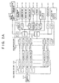
- FIG.2A is a block diagram of a main controlling unit 100 and a field controlling unit 200.
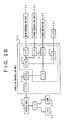
- FIG.2B is a block diagram of one of satellite controlling units 300 shown in FIG.2A.
- the controlling system of the dice game machine 10 is roughly divided into the main controlling unit 100, the field controlling unit 200 and the satellite controlling unit 300 provided for each of the eight satellites 18. These controlling units are provided on a main controlling circuit board, a field controlling circuit board and satellite controlling circuit boards, respectively.
- the main controlling unit 100 comprises two main central processing units (CPUs) 110 and 130.
- the two CPUs 110 and 130 are connected to each other.
- the main CPU 130 is connected to a main controlling CPU 210 of the field controlling unit 200 via an optical communication unit which comprises an optical cable and communication controlling IC interfaces (I/Fs).
- the main CPU 130 is also connected to a CPU 320 provided in each of the satellite controlling units 300 via the respective optical communication units.
- the main CPU 130 is connected to a display unit 131 and a display unit 132 via the respective input/output controlling IC interfaces (I/Fs).
- the main CPU 110 is connected to a motor driving unit 112 and a dice throwing mechanism 114 via an input/output controlling IC I/F.
- the motor driving unit 112 is connected to a dice collecting mechanism 113.
- a clock IC is connected to the main CPU 110.
- the CPU 110 is connected to illumination units 115 and 117 via respective input/output controlling IC I/Fs.
- An operational unit 116 is connected to the I/F between the illumination unit 117 and the CPU 110.
- the main CPU 110 is connected to a cathode ray tube (CRT) via a video IC.
- the CPU 110 is also connected to a printer 120 and an audio unit via respective input/output controlling IC I/Fs.
- Each of the connections between each of the illumination units 115 and 117 and the display unit 132 and the corresponding input/output controlling IC I/Fs comprises an optical communication unit similar to that provided between the CPU 130 and the CPU 210.
- the field controlling unit 200 comprises a CPU 210 which controls an entire function of the field controlling unit 200.
- the CPU 210 is connected to a sub CPU 320 of each of the satellite controlling units 300 via respective optical units similar to the above-mentioned optical unit.
- the CPU 210 is connected to a detection unit 220 via an input/output controlling IC I/F comprising an optical communication unit similar to the above-mentioned optical communication unit.
- Each of the satellite controlling unit 300 comprises a main CPU 310 and two sub CPUs 320 and 330.
- the main CPU 310 and the sub CPUs 320 and 330 together control an entire function of the satellite controlling unit 300.
- the sub CPUs 320 and 330 are connected to each other and are connected to the main CPU 310 via an input/output controlling IC I/F.
- the sub CPU 320 is also connected to the shooting button 26 via an analog to digital (A/D) converter 323.
- the sub CPU 330 is connected a liquid crystal display (LCD) 331.
- the main CPU 310 is connected to a display unit 340 via an optical communication unit similar to the above-mentioned optical communication unit.
- the display unit 340 is further connected to a light emitting diode (LED) 341 and a lamp 342 via an input/output controlling IC I/F.
- LED light emitting diode
- the present controlling system uses optical communication units at various connections so as to achieve a high-speed signal transmission.
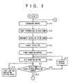
- FIGS.3 and 4 are parts of a flowchart for explaining a main operation of the dice game machine 10.
- the main CPU 130 of the main controlling unit 100 displays on the display unit 20 shown in FIG.1A general information including progression and rules of the game, any time if it is necessary, by using the display unit 132 which itself has a CPU having an image controlling function. Additionally, the CPU 110 controls the illumination units 115 and 117 to light illumination lamps provided in the illumination unit 16 shown in FIG.1A in accordance with a predetermined program. The CPU 110 also controls the audio unit 121 to output various sounds and music in accordance with a musical instrument digital interface (MIDI). By the illumination and the sounds, the dice game machine 10 excites the players and attracts people in an area around the dice game machine 10. It should be noted that the operational unit 116, the CRT 119 and the printer 120 in the main controlling unit 100 are provided for mainly a maintenance purpose, for example, for checking a condition of the dice game machine 10.
- a maintenance purpose for example, for checking a condition of the dice game machine 10.
- the CPU 310 of each of the satellites 18 calculates, in step 1 (hereinafter step is abbreviated as S), the present points of each player. Then, each player inputs, in S2, information representing that the player intends to play a next game through the respective satellite 18. The information is detected by the satellite controlling unit 300, and the information is transferred to the main CPU 130 of the main controlling unit 100 via the sub CPU 320. The CPU 130 recognizes, in S3, the satellites 18 which are currently being used by the players. A number indicating device is provided on the display unit 340 of each of the satellites 18 so as to indicate the present points of the player and the points set for the next game. The setting of the points for the next game can be performed as follows.
- the sub CPU 320 which detects the information representing that the corresponding player intends to play the next game, controls the sub CPU 330 to display on the LCD 331 guidance instructing the player to set the points.
- the point information is sent to the main CPU 310.
- the main CPU 310 displays the point information on the number indicating device of the display unit 340.
- the CPU 330 displays on the LCD 331 information on the progress of the game to inform each player of the current stage of the game.
- the CPU 130 of the main controlling unit 100 selects the shooter, in S4, in accordance with a predetermined program.
- the CPU 130 sends corresponding information to the satellite controlling unit 300 of the selected satellite 18.
- the sub CPU 320 of the selected satellite 18 sends, in S5, information to the shooting button 26 to light the lamp 342 which is provided in the shooting button 26.
- the shooter (the player of the corresponding satellite 18) hits the shooting button 26 in S6.
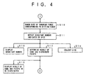
- the hitting force exerted on the shooting button 26 is converted into an electric signal by the aforementioned hitting force detecting mechanism.
- the electric signal is supplied to the A/D converter so that an analog electric signal is converted into a digital signal which represents an intensity of the electric signal.
- the digital signal is then supplied to the main CPU 310.
- the main CPU 310 lights, in S9, a corresponding number of a plurality of LEDs 341 (shown in FIG.5) provided around the shooting button 26 via the display unit 340 in accordance with the digital signal, the number being in proportion to the hitting force exerted on the shooting button 26.
- This lighting operation of the LEDs 341 is limited to the selected satellite 18. Accordingly, if one of the players other than the shooter hits the shooting button 26 on a non-selected satellite 18, the LEDs 341 around the shooting button 26 on the non-selected satellite 18 do not light.
- the LEDs 341 are lighted almost at the same time the corresponding shooting button 26 is hit. Accordingly, the player can visually recognize the hitting force applied to the shooting button 26. This makes the game more enjoyable for the players.
- the throwing force applied to the dice is varied correspondingly to the hitting force. If the hitting force exceeds a maximum magnitude of the predetermined effective range, the throwing force of the dice is maintained at a predetermined maximum throwing force so as to limit a power applied to the dice. This is to prevent damage to the dice, and also to prevent the shooting button 26 from being hit by an excessive hitting force. On the other hand, if the hitting force does not reach a predetermined minimum magnitude of the effective range, the dice are not thrown by the dice throwing mechanism. This is to prevent an undesired controlled throwing of the dice. That is, if the dice are thrown by a very small throwing force, the dice may be thrown with only a few rolls. This may allow to the shooter to control the resultant number indicated by the dice. If the resultant number of the dice is controlled by the shooter, the enjoyment of the game is decreased.
- the number of the LEDs 341 to be lighted is determined as follows. That is, when the hitting force does not reach the minimum magnitude of the effective range, no LED 341 is lighted. When the hitting force corresponding to the minimum magnitude of the effective range is applied onto the shooting button 26, only one LED 341 is lighted. On the other hand, when the hitting force corresponds to the maximum magnitude of the effective range, all of the LEDs 341 are lighted. Accordingly, the players can learn visually the effective range of the hitting force, and thus the players can control a magnitude of the hitting force applied onto the shooting button 26 within the predetermined effective range.
- the LEDs 341 shown in FIG.5 are used as illumination when no game is performed by the dice game machine 10. In this condition, the main CPU 310 controls the lighting of the LEDs 341.
- the program for controlling the dice throwing mechanism includes the following procedures.
- the hitting force applied to the shocting button 26 does not reach the minimum magnitude of the predetermined effective range in S7, guidance which requests the shooter to hit the shooting button 26 again using more power is displayed, in S8, on the LCD 331 of the satellite 18.
- the dice game machine 10 automatically throws the dice toward the field 24 so as to eliminate an undesired delay of the game.
- a signal including information regarding a magnitude of the hitting force is sent to the CPU 130 of the main controlling unit 100 via the sub CPU 320 after the signal is converted into a digital signal by the A/D converter 323.
- the information regarding the magnitude is then sent to the main CPU 110, and the main CPU 110 controls the dice throwing mechanism 114 to throw the dice with a power corresponding to the magnitude of the hitting force.
- the dice throwing mechanism 114 throws, in S10, the dice toward the field 24 with the corresponding force.
- the dice thrown by the dice throwing mechanism 114 fly above the field 24 and hit a wall provided on an opposite side of the field 24. The dice then fall on the field 24 and stop after rolling. It should be noted that when the hitting force applied to the shooting button 26 is not sufficient, the dice fall on the field 24 before they hit the wall.
- the CPU 210 which receives the information operates the detection unit 220.
- the detection unit 200 detects, in S11, the resultant number of each of the dice on the field 24.
- the information regarding the resultant number is sent to the main CPU 130 of the main controlling unit 100 via the CPU 210 off the field controlling unit 200.
- the information is then sent to the display unit 131 which includes the dot indicating unit 21 shown in FIG.1C.
- the resultant numbers indicated by the dice are displayed, in S13, on the dot indicating unit 21.
- the CPUs 110 and 130 determine the result of the game for each satellite 18 (each player), and then the points are distributed, in S12, to the satellites 18 in accordance with the result.
- the result of the game and the points to be distributed to the satellites 18 are displayed on the display unit 20.
- the CPU 210 sends corresponding information to the main CPU 110 of the main controlling unit 100.
- the main CPU 110 operates the dice collecting mechanism 113, in S14, to collect the two dice on the field 24 so that the dice are returned to a predetermined position in the dice throwing mechanism 114.
- the main CPU 110 controls the display unit 132 to display the guidance of the game on the display unit 20 shown in FIG.1C. Additionally, the CPU 110 controls the CPUs 320, 330 of each of the satellites 18 to display the guidance of the game on the LCD 331.
- the operation of the dice game machine 10 returns to the step 1 to repeat the above-mentioned procedures so as to perform a next game.
- the number of CPUs and the function assigned to each of the CPUs are not limited to the above-mentioned structure. However, it is necessary to determine the configuration of the CPUs so that a smooth progression of the game is not prevented due to a long processing time for performing each of the above-mentioned steps and a long data transmission time between the CPUs and between each unit and the CPUs.
- FIG.6 is a perspective view of the inside of the main body 12 of the dice game machine 10 shown in FIGS.1A, 1B and 1C.
- the dice throwing mechanism 114 and the dice collecting mechanism 113 are provided around the field 24 inside the main body 12.
- a front side of the field 24 is connected to a slope 30.
- the dice on the field 24 are moved to the slope 30 by the dice collecting mechanism 113.
- the dice slide along the slope 30 and are collected in the center of the bottom side of the slope 30 where a throwing plate of the dice throwing mechanism 114 is positioned. Thus, the dice are placed on the throwing plate.
- the dice throwing mechanism 114 is provided in a space 32 shown in FIG.6.
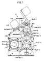
- FIG.7 is a side view of the dice throwing mechanism 114.
- FIG.8 is a front view of the dice throwing mechanism 114.
- the dice throwing mechanism 114 is constituted as a single unit so that an entire mechanism is removed from the main body of the dice game machine 10. Accordingly, a maintenance and repair of the dice throwing mechanism 114 is easy.
- the dice throwing mechanism 114 comprises the above-mentioned throwing plate 42, a driving AC motor 44, and an electromagnetic powder clutch 46.
- the electromagnetic powder clutch 46 controls transmission of a driving force of the driving AC motor 44. These parts are connected by pulleys and timing belts.
- the AC motor 44 and the electromagnetic powder clutch 46 are mounted on a side plate 48A. As shown in FIG.9, a pulley D is mounted on a shaft of the AC motor 44. A pulley C1 is mounted on a power input side of the electromagnetic powder clutch 46, and a pulley C2 is mounted on a power output side of the electromagnetic powder clutch 46. The pulley D of the AC motor 44 is coupled to the pulley C1 of the electromagnetic powder clutch 46 by a timing belt C.
- a shaft 50 is provided above the electromagnetic powder clutch 46.
- the shaft 50 is rotatably supported by the side plate 48A and a side plate 48B.
- Pulleys B and A2 are mounted on the shaft 50.
- the pulley B is positioned directly above the pulley C2 mounted on the power output side of the electromagnetic powder clutch 46.
- the pulley B and the pulley C2 are coupled by a timing belt B.
- a diameter of the pulley B is greater than a diameter of the pulley C2 so that a predetermined reduction ratio is obtained.
- a tension of the timing belt C is adjusted by slightly moving a position of the AC motor 44 or the electromagnetic powder clutch 46.
- a shaft 52 is provided directly above the shaft 50. Similarly to the shaft 50, the shaft 52 is rotatably supported by the side plates 48A and 48B.
- a pulley A1 is mounted on the shaft 52 directly above the pulley A2.
- the pulley A1 and the pulley A2 are coupled by a timing belt A.
- a tension of the timing belt A is adjusted by only an idle roller 54 provided between the pulley A1 and the pulley A2.
- the idle roller 54 is rotatably mounted on the side plate 48B so that the idle roller 54 presses a portion of an outer surface of the timing belt A. Accordingly, an adjusting mechanism such as an idle pulley for adjusting the tension of the timing belt A is not needed in the dice throwing mechanism 114.
- an assembling process of the dice throwing mechanism 114 is simple and the number of parts is reduced.
- Opposite ends of the shaft 52 are extended from the respective side plates 48A and 48B. Angle portions 42a of the throwing plate 42 are mounted on the opposite ends of the shaft 52, respectively.
- the throwing plate 42 is normally positioned at a home position shown in solid lines in FIG.7.
- a photosensor A detects that the throwing plate 42 is in this position.
- the photosensor A has a rotatable lever (not shown in the figures) which rotates by being pressed by a portion of the throwing plate 42. When the rotatable lever is rotated by the throwing plate 42, the rotatable lever interrupts an optical path of the photosensor A, and thus a signal is output from the photosensor A.
- the photosensor A is provided under the throwing plate 42 as shown in FIG.7.
- FIG.10 is a view of the throwing plate 42 viewed from an arrow indicated by B in FIG.7.
- a width W of the throwing plate 42 is twice a width of one of the dice, and thus the two dice are thrown at the same time.
- Two openings 42b are provided in the throwing plate 42.
- a photosensor C is provided under each of the openings 42b.
- the photosensor C has the same structure as that of the photosensor A.
- An extending portion 42c is provided on one of the angle portions 42a of the throwing plate.
- the extending portion 42c is mounted so that an end thereof projects into a slit of a photosensor B, which comprises a photointerrupter and is mounted on the side plate 48A, when the throwing plate 42 reaches an end position which is an end of a rotation of the throwing plate 42. Accordingly, the photosensor B can detect a completion of throwing of the dice.
- each of the timing belts A, B and C comprises a timing belt having a waved inner surface. Since the waves of the timing belts engage with the teeth of the pulleys, there is no problem due to a backlash when gears are used for transmitting a rotational force. Thus, the dice throwing mechanism 114 has a good response with respect to transmission of the rotational force.
- the dice throwing mechanism 114 is accommodated in the space 32 shown in FIG.6.
- the throwing plate 42 of which is at the home position is accommodated in the space 32, the throwing plate 42 corresponds to an opening 30a of the slope 32 shown in FIG.6. Accordingly, the dice slide along the slope 32 and are placed on the throwing plate 42.
- FIG.11 is a flowchart of an operation of the dice throwing mechanism 114.
- the two dice are placed on the throwing plate 42 by the dice collecting mechanism 113. While the dice are collected, each player who intends to play the next game guesses the resultant number and sets the points through the corresponding satellite 18. Additionally, as previously mentioned, one of the satellites 18 is selected to determine the shooter for the next game.
- the AC motor 44 is rotated, in S26, at a predetermined constant rotational speed in a normal direction.
- a small current is supplied, in S28, to the electromagnetic powder clutch 46.
- the small current is not sufficient for activating the electromagnetic powder clutch 46. Accordingly, in this state, the pulley C1 of the power input side of the electromagnetic powder switch 46 is rotated by the timing belt C while the pulley C2 of the power output side of the electromagnetic powder clutch 46 is not rotated. That is, the rotational force of the AC motor 44 is not transmitted to the pulley C2 of the electromagnetic powder clutch 46.
- the shooting button 26 is connected to a voltage signal generating unit 60 as shown in FIG.12.
- the voltage signal generating unit 60 comprises a piezoelectric element which generates a voltage a magnitude of which corresponds to the magnitude of the hitting force applied onto the shooting button 26.
- the shooting button 26 is supported by a bracket 64 protruding from a bracket 62. Since the shooting button 26 is hit by the shooter, a rubber cushion is provided on a bottom side of the shooting button 26.
- a pressing member 68 is provided on the bottom of the shooting button 26. When the pressing button 26 is hit by the shooter, the hitting force is applied to the voltage signal generating unit 60, and the voltage signal corresponding to the hitting force is output from the voltage signal generating unit 60.
- the voltage signal is converted into a digital signal having 128 levels by the A/D converter 323 (refer to FIG.2A).
- the CPUs in the dice game machine 10 control a current setting circuit as current supplying means so that a predetermined current is supplied, in S36, to the electromagnetic powder clutch 46.
- the analog to digital conversion and the supply of the current to the electromagnetic powder clutch 46 are achieved by known circuitry, and thus descriptions thereof will be omitted.
- FIG.13 is a side view of another example of the shooting button 26 and the voltage signal generating unit 60.
- the shooting button 26 has the pressing member 68 which slides in a hole provided in a portion protruded from a center of a bottom of the shooting button 26. The hitting force applied onto the pressing button 26 is transmitted to the voltage signal generating unit 60 via a spring.
- the powder clutch 46 transmits a torque in response to the current supplied thereto. That is, when the magnitude of the hitting force is not sufficient, the current supplied to the powder clutch 46 is not sufficient to fully activate the electromagnetic powder clutch 46. Accordingly, a rotational force (torque) of the AC motor 44 is transmitted to the pulley C2 of the power output side of the electromagnetic powder clutch 46 with a slippage. The torque transmitted through the electromagnetic powder clutch 46 is then transmitted to the shaft 52 via the timing belt B and the timing belt A. Thus, the throwing plate 42 mounted to the shaft 52 is rotated, and thus the dice placed on the throwing plate 42 are thrown toward the field 24. Accordingly, the throwing power of the dice corresponds to the magnitude of the current supplied to the electromagnetic powder clutch 46.
- the routine After the electromagnetic powder clutch 46 is activated, it is determined, in S38, whether the throwing plate 42 has reached the end position. If the throwing plate 42 does not reach the end position in a predetermined time period, the routine proceeds to S32 where the error signal is output. If it is determined that the throwing plate 42 has reached the end position, the AC motor 44 is then reversed, in S40, so as to return the throwing plate 42 to the home position, and then the routine is ended.
- the AC motor 44 is rotated in S26 before the shooting button 26 is hit. This is to eliminate a starting time of the AC motor 44. That is, a response time period from the hitting of the shooting button 26 to the throwing of the dice can be reduced. Additionally, the response time period is reduced by supplying the small current in S28. That is, an initial magnetization in the electromagnetic powder clutch 46 is performed beforehand to reduce a raising time of the magnetization in the electromagnetic powder clutch 46. In the present embodiment, an intensity of the small current supplied to the electromagnetic powder clutch 46 is a few milliamperes.
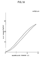
- FIG.14 is a graph showing a relationship between a magnetizing current and a slip torque of the electromagnetic powder clutch 46.
- the slip torque of the electromagnetic powder clutch 46 is in proportion to the magnetizing current supplied to the electromagnetic powder clutch 46.
- a slip torque proportional to the magnetizing current is obtained.
- the magnetizing current is varied in a range from a few milliamperes to about 2.5 amperes so as to control the magnitude of the throwing force.
- the dice throwing mechanism 114 can throw the dice in a very short time, and the throwing force of the dice can be controlled by varying the magnitude of the hitting force applied to the shooting button 26.
- the shooter can play the game as if the shooter throws the dice by the shooter's own hand.
- the dice throwing mechanism is not limited to the specifically disclosed embodiment, and other mechanisms which can vary a throwing force according to an action of the shooter may instead be used.
- a throwing mechanism may be used which uses a photo-sensing system comprising a light-emitting element and a photosensor.
- the photo sensing system detects a passage of the shooter's hand at two predetermined points. A time difference between the two points is calculated and the throwing force of the dice is controlled according to the time difference. That is, the throwing force of the dice is controlled by a moving speed of the shooter's hand.
- the throwing force may be generated by ejection of air from an air compressor.
- the throwing force can be varied by a pressure control valve provided on a air passage between the compressor and an eject nozzle.
- the dice collecting mechanism 113 basically comprises a collecting mechanism, a fillip mechanism and an attracting mechanism.
- the collecting mechanism moves the dice on the field 24 toward the slope 30 (refer to FIG.6).
- the fillip mechanism drops one of the dice off of the other when the dice on the slope 30 are positioned on top of each other so that the dice are positioned side by side.
- the attracting mechanism collects the dice on the bottom side of the slope 30 in the center of the bottom side of the slope 30.
- the collecting mechanism comprises a collect bracket 70 which moves in a direction indicated by an arrow Y in FIG.6 and parallel to a surface of the field 24.
- the collect bracket 70 is positioned in a rear position, which is opposite to the slope 30, when the dice are thrown.
- the collect bracket 70 moves toward the slope 30 (in the Y direction) while pressing the dice on the field 24.
- a pair of rails 72A and 72B are arranged on the left side and the right side of the field 24, respectively.
- Timing belts 74A and 74B are provided inside the respective rails 72A and 72B.
- the timing belt 74A is supported by pulleys 76A and 78A at its opposite ends.
- the timing belt 74B is supported by pulleys 76B and 76C at its opposite ends.
- slide plates 71A and 71B are attached to one side of each of the timing belts 74A and 74B, respectively.
- the slide plates 71a and 71B are slidable along the respective rails 72A and 72B.
- Opposite ends of the collect bracket 70 are mounted to the respective slide plates 71A and 71B.
- the collect bracket 70 moves parallel to the surface of the field 24.
- each of the rails 72A and 72B has a cross section having a channel-like shape. Side walls of each of the rails 72A and 72B protrude outwardly. A plurality of roller bearings 73 are provided on a bottom surface each of the slide plates 71A and 71B. The roller bearings are placed against the side walls of the rails 72A and 72B so that the each of the slide plates 71A and 71B can freely slide along the respective slide rails 72A and 72B.
- FIG.16 is an illustration of the rails 72A and 72B and the collect bracket 70.
- FIG.16 it is assumed that only the slide plate 71A is driven, and the slide plate 71B is freely moved.
- a moment indicated by an arrow R1 is applied to the slide plate 71B.
- a moment indicated by an arrow R2 is applied to the slide plate 71B.
- both of the slide plates 71A and 71B are synchronously driven by the respective timing belts 74A and 74B.
- the timing belt 74A to which the slide plate 71A is mounted is driven by a pulley 78A which is rotated by an AC motor 84.
- a pulley 78B which drives the timing belt 74B is rotated by a timing belt 80 provided between the pulley 78A and the pulley 78B. Accordingly, the timing belts 74A and 74B are moved in synchronization with each other.
- a tension of the timing belt 30 is adjusted by an idle pulley 82.
- the above-mentioned AC motor 84 is a reversible type AC motor with a four-pole/two-pole switching function.
- the AC motor 84 When moving the dice, the AC motor 84 is switched to a four-pole drive to generate a high torque.
- the collect bracket is returned to a rear position, the AC motor 84 is switched to a two-pole drive to obtain a high speed. Accordingly, the collect bracket 70 is moved faster when the collect bracket 70 is returned, and thus a waiting time due to the return of the collect bracket 70 is reduced.
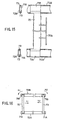
- FIG.17A is a plan view of a portion of the rail 72a and a slide plate 71A
- FIG.17B is a front view of the portion of the rail 71A and the slide plate 71A shown in FIG.17A
- FIG.17C is a side view of the portion of the rail 72A and the slide plate 71A shown in FIG.17A.
- a sensor 90 comprising a photointerrupter is mounted to a rail 72A via a bracket 96 near both ends of the rail 72A. A position of each sensor 90 corresponds to an end of the stroke of the slide plate 71A.
- a sensor bracket 92 is provided on the slide plate 71A.
- An end of the sensor bracket 92 protrudes into the slit of each sensor 90 when the slide plate 71A moves to the respective end of the stroke.
- the end of the sensor bracket 92 interrupts an optical path of each sensor 90, and thereby it is detected that the slide plate 71A is moved to the end of the stroke.
- a rotation of the AC motor 84 is stopped according to the detection of the slide plate 71A in a software manner.
- a limit switch 94 is provided to stop the rotation of the AC motor 84 in a hardware manner.
- the limit switch 94 is operated, when an arm of the limit switch 94 is pressed by a portion of the sensor bracket 92, so as to interrupt a current supplied to the AC motor 84. That is, if the AC cannot be stopped by means of the sensor 90, the limit switch 94 interrupts the current to the AC motor 84 to stop the AC motor 84. Accordingly, the limit switch 94 is positioned behind the sensor 90 so that the limit switch 94 is not operated during a normal operation.
- a stopper 98 is further provided at each end of the rail 72A to mechanically stop the movement of the slide plate 71A. Accordingly, if the slide plate 71 should move continuously after passing the limit switch 94, the slide plate 91A is forcibly stopped by the stopper 98.
- the stopper 98 is also provided to both ends of the rail 92B.
- the AC motor 84 which drives the slide plates 72A and 72B is stopped at the end of the stroke by the software control and then the hardware control.
- the AC motor 84 is stopped even when an error occurs in the software control.
- the limit switch 94 is not provided to stop the AC motor 84 by the hardware control, a coil of the AC motor may burn out due to an overload when the slide plates 71A and 71B are mechanically stopped.
- the present embodiment prevents such a problem by using the double stop system comprising the software control and the hardware control.
- the collect bar 70a is provided to drop the upper die from the lower die.
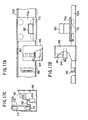
- FIG.18 is a side view of the collect bar 70a.
- the collect bar 70a protrudes from a front side of the collect bracket 70 at a height which is greater than a height of one of the dice.
- a distance from the front side of the collect bracket 70 to a protruding end of the collect bar 70a is greater than a length of one half of a diagonal line of a face of one of the dice. Accordingly, the upper one of the dice positioned on the other is dropped onto the field 24 before the lower one of the dice is moved by the collect bracket 70.
- FIG.19 is a side view of the fillip mechanism and the attracting mechanism.
- the fillip mechanism includes a fillip bar 404 which is mounted on a slide plate 402 which slides along a rail 400 as shown in FIGS.6 and 19.
- the fillip bar 404 is provided to drop an upper die to a bottom side of the slope 30 when two dice are aligned in a longitudinal direction on the slope 30 as shown in FIG.19.
- the slide plate 402 is moved along the rail 400 by a mechanism similar to that of the above-mentioned collect mechanism. That is, the mechanism comprises the rail 400, pulleys 406 and 408, a motor 410 which drives the pulley 406 and a timing belt 412 which is provided between the pulleys 406 and 408.
- FIG.20 is a plan view of the fillip mechanism.
- the fillip bar 404 is moved from a home position (indicated by dotted lines) in a direction indicated by an arrow X1 to traverse the slope 30. If the two dice are aligned one on the other in a longitudinal direction of the field 24, the upper one is pushed off of the lower one by an end of the fillip bar 404. Thus, the two dice are aligned at the bottom of the slope side by side. If the two dice are aligned in the longitudinal direction at a side opposite to the home position, the fillip mechanism is not effective. In order to eliminate this problem, a thin bar 414 is provided on the side opposite to the home position side as shown in FIG.20.
- the thin bar 414 protrudes from the side opposite to the home position side by a distance which is equal to or more than a length of a side of one of the dice. Due to an action of the thin bar 414, the dice are always positioned at the bottom side of the slope 30 at a distance away from the side opposite to the home position side, the distance being at least the length of the side of one of the dice.
- the fillip bar 404 is moved from the home position to the opposite side of the slope 30 (end position), and then returned to the home position.
- the slide plate 402 positioned at the home position and the end position is detected by sensors provided on the rail 400 in the same manner as the detection of the collect bracket 70.
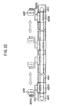
- the attracting mechanism includes a pair of attract bars 426A and 426B which are mounted on slide plates 422A and 422B via brackets 424A and 424B, respectively, as shown in FIGS.6 and 19.
- the slide plates 422A and 422B slide along a rail 420 in opposite directions to each other.
- a pad 428 shown in FIGS.21A and 21B is attached on an end of each of the attract bars 426A and 426B.
- the dice are collected to a center of the bottom side of the slope 30, where the throwing plate 42 is located, by the movement of the pads 428.
- the slide plates 422A and 422B are moved by a mechanism similar to that provided in the collect mechanism. That is, the mechanism of the fillip mechanism comprises the rail 420, pulleys 429 and 430 which are provided at opposite ends of the rail 420, a motor 432 which drives the pulley 429 and a timing belt 434 provided between the pulleys 429 and 430. Since the slide plates 422A and 422B are mounted on opposite sides of the timing belt 434, respectively, the slide plates 422A and 422B move in opposite directions to each other. In FIG.22, end positions of the pads 428 and the respective slide plates 422A and 422B are indicated by dotted lines, and home positions thereof are indicated by solid lines.
- the dice are collected to the center of the slope 30.
- the dice are placed on the throwing plate 42 of the dice throwing mechanism.
- the slide plates 422A and 422B positioned at the respective end positions and at the respective home positions are detected by sensors provided on the rail 420 in the same manner as the detection of the collect bracket 70.
- the pad 128 comprises two discs 428a and 428b and springs 128c provided between the discs 428a and 428b as shown in FIGS.21A and 21B.
- the disc 428a has an opening in the center thereof, and the disc 428b has a shaft 428d protruding from the center thereof.
- the shaft 428d of the disc 428b fits in the opening of the disc 428a so that the disk 428a can move with respect to the disk 428b with an elastic force generated by the springs 128c. Accordingly, the dice are pinched by the pads 128 softly which prevents the dice from being damaged by a pressing force of the pads 428.
- the pads 428 may be made of an elastic material such as rubber or sponge which also provides an elastic force.
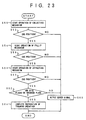
- FIG.23 is a flowchart of the operation of the dice collecting mechanism 113.
- the operation of the dice collecting mechanism 113 is started after the dice are thrown toward the field 24 and the resultant number indicated by each of the dice is detected.
- the operation of the collecting mechanism is started in S50.
- the collect bracket 70 is moved along the field 24 from the home position toward the slope 30.
- the two dice on the field 24 are moved by the collect bracket 70. If one of the dice is positioned on the other one of the dice, the upper one is dropped off to the field 24 by the collect bar 70a.
- the operation of the fillip mechanism is then started, in S56, so as to move the fillip bar 404 from the home position, which is on one side of the slope 30, to the end position which is on the opposite side of the slope 30. If the two dice are aligned in the longitudinal direction of the field 24, the upper one of the dice is dropped by the fillip bar 404. It is then determined, in S56, whether or not the fillip bar has reached the end position.
- an error signal is output, in S66, so that the operation of the dice collecting mechanism 113 is stopped.
- the operation of the attracting mechanism is started in S58. At this time, the collect bracket 70 and the fillip bar 404 are returned to their home positions.
- the field 24 has a large area so that the dice can freely roll on the field 24. This is because the players have guessed the resultant number and get excited while the dice are freely rolled until the dice finally stop. This provides enjoyment to the game performed by the dice game machine 10 according to the present invention. Accordingly, it is preferable that the dome 22 which covers the field 24 is has a sufficient height so that the dice do not hit the dome 22 before they hit the wall provided on a rear side of the field 24. Additionally, it is preferable that the movement of the dice can be observed by all of the players standing in front of the satellites 18.
- the present embodiment is described by using the dice game machine 10 which uses two dice, a single die may be used. Additionally, a die-like object having, for example, a polyhedron shape may be used as an element which determines the resultant number. A flat piece such as a coin may also be used as means for determining a game result. The concept of the dice throwing mechanism may be applied to a ball throwing mechanism of a roulette game machine.
Landscapes
- Engineering & Computer Science (AREA)
- Multimedia (AREA)
- Physics & Mathematics (AREA)
- General Physics & Mathematics (AREA)
- Pinball Game Machines (AREA)
- Toys (AREA)
Claims (24)
- Spielvorrichtung (10), die zum Durchführen eines Spiels mit einer Vielzahl von Spielern geeignet ist, welche Spielvorrichtung enthält:wenigstens eine Einwirkungseinrichtung (26, 60) zum Erzeugen einer Größenausmaßinformation, die ein durch einen der Spieler bestimmtes Größenausmaß angibt, wobei die Einwirkungseinrichtung von einem der Spieler derart manuell betätigbar ist, daß das von der Größenausmaßinformation angegebene Größenausmaß durch den einen der Spieler willkürlich veränderbar ist,eine Nachweiseinrichtung zum Nachweisen der von der Einwirkungseinrichtung erzeugten Größenausmaßinformation, gekennzeichnet durch:wenigstens einen tatsächlichen Gegenstand mit einer Einrichtung zum Bestimmen eines Ergebnisses des Spiels, wobei das Ergebnis des Spiels von der Folge eines Wurfes des Gegenstands abhängt, wobei der Gegenstand, nachdem er geworfen worden ist, in einer einer Vielzahl von Orientierungen zur Ruhe kommt und der Wurfvorgang des Gegenstands von den Spielern beobachtbar ist; undeine Antriebseinrichtung (114) zum Anlegen einer Antriebskraft an den Gegenstand, so daß der Gegenstand geworfen wird, wobei ein Größenausmaß der Antriebskraft in Übereinstimmung mit der von der Nachweiseinrichtung nachgewiesenen Größenausmaßinformation gesteuert wird.
- Spielvorrichtung nach Anspruch 1, dadurch gekennzeichnet, daß die Einwirkungseinrichtung einen Knopf (26) aufweist, der von dem einem der Spieler gestoßen wird, und daß die Nachweiseinrichtung ein piezoelektrisches Bauelement (60) enthält, das eine auf den Knopf ausgeübte Stoßkraft in ein elektrisches Signal umwandelt, das ein Größenausmaß der Stoßkraft angibt.
- Spielvorrichtung nach Anspruch 1 oder 2, dadurch gekennzeichnet, daß die Antriebseinrichtung eine Antriebsenergiequelle (44), ein Antriebsglied (42) und eine Antriebskraft-Übertragungseinrichtung (46) aufweist, wobei die Antriebsenergiequelle die Antriebskraft mit einer vorbestimmten konstanten Stärke erzeugt, das Antriebsglied die Antriebskraft an den Gegenstand legt und die Antriebskraft-Übertragungseinrichtung die Antriebskraft von der Antriebsenergiequelle auf das Antriebsglied überträgt, während die Stärke der Antriebskraft in Übereinstimmung mit der Größenausmaßinformation vermindert wird.
- Spielvorrichtung nach Anspruch 3, dadurch gekennzeichnet, daß die Antriebsenergiequelle einen Motor (44) aufweist, der eine Drehkraft erzeugt, die Antriebskraft-Übertragungseinrichtung eine Elektromagnetpulverkupplung (46) enthält, das Antriebsglied ein schwenkbares Glied (42) enthält, die von dem Motor erzeugte Drehkraft über die Elektromagnetpulverkupplung auf das schwenkbare Glied derart übertragen wird, daß die Antriebskraft durch einen Schwenkvorgang des schwenkbaren Glieds an den Gegenstand gelegt wird, und die Stärke der Antriebskraft durch verändern eines Schlupfdrehmoments der Elektromagnetpulverkupplung gesteuert wird.
- Spielvorrichtung nach irgendeinem der Ansprüche 1 bis 4, gekennzeichnet durch das weitere Vorsehen einer Einrichtung zum Verhindern eines Betriebs der Antriebseinrichtung, wenn das von der Größenausmaßinformation angegebene und von der Nachweiseinrichtung nachgewiesene Größenausmaß außerhalb eines vorbestimmten Bereiches ist.
- Spielvorrichtung nach irgendeinem der Ansprüche 1 bis 5, gekennzeichnet durch das weitere Vorsehen einer Einrichtung zum Anzeigen des von der Größenausmaßinformation angegebenen und über die Einwirkungseinrichtung eingegebenen Größenausmaßes, so daß wenigstens der eine der Spieler, der die Einwirkungseinrichtung betätigt, das Größenausmaß visuell erkennt.
- Spielvorrichtung nach Anspruch 6, dadurch gekennzeichnet, daß die Einrichtung zum Anzeigen des Größenausmaßes eine Vielzahl von Leuchtbauelementen (341) aufweist, wobei die Anzahl der Leuchtbauelemente, die aufleuchten, in Übereinstimmung mit der Größenausmaßinformation geändert wird.
- Spielvorrichtung nach irgendeinem der Ansprüche 1 bis 7, dadurch gekennzeichnet, daß der Gegenstand einen Würfelkörper enthält und das Ergebnis des Spiels in Übereinstimmung mit einer Zahl bestimmt wird, die auf einer Fläche des Würfelkörpers angegeben ist.
- Spielvorrichtung nach Anspruch 8, gekennzeichnet durch das Vorsehen eines Feldes (24), auf dem der Würfelkörper gerollt wird, wobei das Ergebnis des Spiels in Übereinstimmung mit der Zahl bestimmt wird, die auf der Fläche des Würfelkörpers auf dem Feld angegeben ist, welche Fläche entgegengesetzt zu einer Fläche ist, die eine Oberfläche des Feldes berührt.
- Spielvorrichtung nach Anspruch 9, gekennzeichnet durch das weitere Vorsehen einer Einrichtung zum Nachweisen der Zahl, die auf der Fläche des Würfelkörpers angegeben ist, und eine Einrichtung zum Bestimmen des Ergebnisses des Spiels für jeden der Spieler in Übereinstimmung mit der Zahl.
- Spielvorrichtung nach Anspruch 1, dadurch gekennzeichnet, daß die Einwirkungseinrichtung enthält:eine Eingabeeinheit (26, 60), die ein Signal erzeugt, das sich in Abhängigkeit von einer Einwirkung ändert, die von einem Spieler auf die Eingabeeinheit ausgeübt wird; unddaß die Antriebseinrichtung enthält:ein Werferglied (42), das den Gegenstand mittels einer Schwenkbewegung zum Feld hin wirft;einen Motor (44), der sich mit einer konstanten Drehzahl dreht;eine elektromagnetische Kupplung (46), die zwischen dem Motor und dem Werferglied zum Übertragen einer Drehkraft von dem Motor auf das Werferglied vorgesehen ist; undeine Stromzufuhreinrichtung zum Zuführen eines Stromes zu der elektromagnetischen Kupplung, wobei die Stärke des zugeführten Stromes in Übereinstimmung mit dem von der Eingabeeinheit erzeugten Signal geändert wird.
- Spielvorrichtung nach Anspruch 11, dadurch gekennzeichnet, daß die elektromagnetische Kupplung eine Elektromagnetpulverkupplung (46) aufweist, die eine Drehkraft des Motors proportional zur Stärke des von der Stromzufuhreinrichtung zugeführten Stromes überträgt.
- Spielvorrichtung nach Anspruch 11 oder 12, dadurch gekennzeichnet, daß zwischen dem Motor und der elektromagnetischen Kupplung sowie zwischen der elektromagnetischen Kupplung und dem Werferglied ein Kraftübertragungsmechanismus vorgesehen ist, der Rollen mit Zähnen an deren Außenflächen und Zahnriemen mit zahnartigem Längsprofil aufweist, das mit den Zähnen der Rollen zusammenarbeitet.
- Spielvorrichtung nach Anspruch 11, 12 oder 13, dadurch gekennzeichnet, daß die Eingabeeinheit einen Stoßknopf (26) und ein piezoelektrisches Bauelement (60) aufweist, wobei das piezoelektrische Bauelement ein Spannungssignal ausgibt, wenn auf den Stoßknopf ein Druck ausgeübt wird, und wobei die Spannung des Spannungssignals von einem unterschiedlichen Größenausmaß der Stoßkraft gesteuert wird, die auf den Stoßknopf ausgeübt wird.
- Spielvorrichtung nach Anspruch 14, gekennzeichnet durch das weitere Vorsehen einer Vielzahl von Leuchtbauelementen (341), die rund um den Stoßknopf angeordnet sind, wobei die Anzahl der Leuchtbauelemente, die aufleuchten, von dem Größenausmaß der auf den Stoßknopf ausgeübten Stoßkraft abhängt.
- Spielvorrichtung nach Anspruch 1, ferner enthaltend:einen Sammelmechanismus zum Sammeln des einen Gegenstands, welcher Gegenstand in Richtung auf ein Feld (24) geworfen wird, das von der Spielvorrichtung definiert ist, und der bei einer willkürlichen Position auf dem Feld zur Ruhe kommt, welcher Sammelmechanismus enthält:ein Sammelglied (70), das sich in Längsrichtung des Feldes über das Feld von einer Rückseite zu einer Vorderseite bewegt, so daß der Gegenstand auf dem Feld zur Vorderseite des Feldes hin aufgrund einer Bewegung des Sammelglieds bewegt wird, wobei das Sammelglied eine Länge hat, die im wesentlichen gleich der Breite des Feldes ist, und wobei der Gegenstand von einer vorbestimmten Position bei der Vorderseite des Feldes her geworfen wird, undein Paar Anziehungsglieder (428), die an der Vorderseite des Feldes vorgesehen sind und sich senkrecht zur Längsrichtung in zueinander entgegengesetzten Richtungen bewegen, wobei der Gegenstand zwischen den Anziehungsgliedern sandwichartig eingefangen und bei der vorbestimmten Position der Vorderseite des Feldes plaziert wird.
- Spielvorrichtung nach Anspruch 16, dadurch gekennzeichnet, daß die Spielvorrichtung von zwei identischen der Gegenstände Gebrauch macht und daß das Sammelglied ein überstehendes Glied (70a) aufweist, das in Richtung auf die Vorderseite des Feldes bei einer Höhe übersteht, die größer als die Höhe eines der Gegenstände ist, wobei die Länge des überstehenden Glieds im wesentlichen gleich der Breite des Feldes ist, und der Abstand des überstehenden Gliedes von einer Vorderkante des Sammelgliedes bis zu einem Ende des überstehenden Gliedes größer als die Hälfte der größten Länge einer Fläche eines der Gegenstände ist, so daß, wenn einer der Gegenstände auf dem anderen der Gegenstände positioniert ist, er von dem überstehenden Glied heruntergeschlagen wird.
- Spielvorrichtung nach Anspruch 16, dadurch gekennzeichnet, daß das Feld ferner eine Schräge (30) an der Vorderseite des Feldes aufweist, so daß ein vom Sammelglied bewegter Gegenstand zu einer Bodenseite der Schräge herabgleitet.
- Spielvorrichtung nach Anspruch 18, dadurch gekennzeichnet, daß die Spielvorrichtung von zwei identischen der Gegenstände Gebrauch macht und ein Erstreckungsglied (404) an der Bodenseite der Schräge vorgesehen ist, wobei das Erstreckungsglied von einer Seite der Schräge zu der anderen Seite der Schräge bewegt wird, das Erstreckungsglied sich bei einer Höhe erstreckt, die größer als die Höhe eines der Gegenstände ist, ein Ende des Erstreckungsglieds auf einer Höhe ist, die geringer als die Höhe des genannten Gegenstands ist, so daß, wenn einer der Gegenstände auf dem anderen der Gegenstände positioniert ist, er von dem einen Ende des Erstreckungsglieds heruntergeschlagen wird.
- Spielvorrichtung nach irgendeinem der Ansprüche 16 bis 19, dadurch gekennzeichnet, daß ein Paar Schienen (72A, 72B) auf beiden Seiten des Feldes vorgesehen ist, jeweils eine Gleitplatte (71A, 71B) verschiebbar an jeder der Schienen vorgesehen ist, entgegengesetzte Enden des Sammelglieds an den jeweiligen Gleitplatten befestigt sind und die Gleitplatten eine zueinander synchrone Bewegung ausführen.
- Spielvorrichtung nach Anspruch 20, dadurch gekennzeichnet, daß ein Stoppglied (98) an jedem Ende wenigstens einer der Schienen vorgesehen ist und ein erster Fühler (90) auf einer Innenseite des Stoppglieds vorgesehen ist, ein zweiter Fühler (94) zwischen dem Stoppglied und dem ersten Fühler vorgesehen ist, eine Bewegung der Gleitplatte mittels einer Softwaresteuerung gestoppt wird, wenn die Gleitplatte von dem ersten Fühler detektiert wird, die Bewegung der Gleitplatte durch eine Hardwaresteuerung gestoppt wird, wenn die Gleitplatte durch den zweiten Fühler detektiert wird, und die Bewegung der Gleitplatten zwangsläufig gestoppt wird, wenn die Gleitplatten mit dem Stoppglied kollidieren.
- Spielvorrichtung, die zum Durchführen eines Spiels mit einer Vielzahl von Spielern geeignet ist, welche Spielvorrichtung enthält:wenigstens einen tatsächlichen Gegenstand, dessen Orientierung von jedem der Spieler direkt erkannt werden kann, wobei der Gegenstand derart gestaltet ist, daß er in einer einer Vielzahl von Orientierungen zur Ruhe kommt, und wobei ein Ergebnis des Spiels durch die Orientierung des Gegenstands bestimmt wird, nachdem er bewegt worden ist;ein Antriebsglied (42) zum Antreiben des Gegenstands, so daß er in irgendeiner der Vielzahl von Orientierungen zur Ruhe kommt; undeine Energiequelle zum Zuführen einer konstanten Energie; gekennzeichnet durcheine zwischen dem Antriebsglied und der Energiequelle vorgesehene Antriebseinrichtung (44) zum Zuführen von Energie von der Energiequelle zu dem Antriebsglied, wobei die zugeführte Energie in Abhängigkeit von einem Wert geändert wird, der der Antriebseinrichtung während des Spielbetriebs zugeführt wird.
- Spielvorrichtung nach Anspruch 22, dadurch gekennzeichnet, daß
die Vorrichtung ein Feld (24) aufweist;
das Antriebsglied ein Werferglied (42) enthält, das den Gegenstand mittels einer Schwenkbewegung in Richtung auf das Feld wirft; und
die Energiequelle einen Motor (44) aufweist, der sich mit konstanter Drehzahl dreht;
wobei die Antriebseinrichtung eine zwischen dem Motor und dem Werferglied vorgesehene elektromagnetische Kupplung (46) zum Übertragen einer Drehkraft vom Motor auf das Werferglied (42) aufweist und die Antriebseinrichtung eine Stromzufuhreinrichtung zum Zuführen eines Stroms zu der elektromagnetischen Kupplung enthält, welcher Strom in Abhängigkeit von einem Wert geändert wird, der während des Spielbetriebs zugeführt. - Spielvorrichtung nach Anspruch 22, dadurch gekennzeichnet, daß die Spielvorrichtung ein Feld (24) aufweist, auf das der Gegenstand geworfen wird; und
ferner enthaltend einen Sammelmechanismus zum Aufsammeln des Gegenstands von einer willkürlichen Position auf dem Feld (24), welcher Sammelmechanismus enthält:ein Sammelglied (70), das über das Feld (24) in einer Längsrichtung des Feldes von einer Rückseite zu einer Vorderseite bewegbar ist, so daß der Gegenstand auf dem Feld in Richtung auf die Vorderseite des Feldes durch eine Bewegung des Sammelgliedes bewegt wird, wobei das Sammelglied eine Länge hat, die gleich der Breite des Feldes ist, und der Gegenstand von einer vorbestimmten Position der Vorderseite des Feldes aus geworfen wird; undein Paar Anziehungsglieder (428), die an der Vorderseite des Feldes vorgesehen sind und sich in zueinander entgegengesetzten Richtungen senkrecht zur Längsrichtung bewegen, wobei der Gegenstand sandwichartig zwischen den Anziehungsgliedern eingefangen wird und bei einer vorbestimmten Position der Vorderseite des Feldes plaziert wird.
Applications Claiming Priority (6)
| Application Number | Priority Date | Filing Date | Title |
|---|---|---|---|
| JP22382994A JP3757426B2 (ja) | 1994-09-19 | 1994-09-19 | ゲーム駒の回収機構、及びゲーム装置 |
| JP223828/94 | 1994-09-19 | ||
| JP22382994 | 1994-09-19 | ||
| JP223829/94 | 1994-09-19 | ||
| JP22382894 | 1994-09-19 | ||
| JP22382894A JP3694905B2 (ja) | 1994-09-19 | 1994-09-19 | ゲーム装置 |
Publications (3)
| Publication Number | Publication Date |
|---|---|
| EP0701849A2 EP0701849A2 (de) | 1996-03-20 |
| EP0701849A3 EP0701849A3 (de) | 1997-08-27 |
| EP0701849B1 true EP0701849B1 (de) | 2002-05-22 |
Family
ID=26525710
Family Applications (1)
| Application Number | Title | Priority Date | Filing Date |
|---|---|---|---|
| EP95306429A Expired - Lifetime EP0701849B1 (de) | 1994-09-19 | 1995-09-13 | Spielvorrichtung mit einem Körper dessen Bewegung ein Ergebnis eines Spieles bestimmt |
Country Status (7)
| Country | Link |
|---|---|
| US (2) | US5707061A (de) |
| EP (1) | EP0701849B1 (de) |
| CN (1) | CN1127149A (de) |
| AU (1) | AU688550B2 (de) |
| DE (1) | DE69526763T2 (de) |
| ES (1) | ES2177608T3 (de) |
| TR (1) | TR199501143A2 (de) |
Families Citing this family (17)
| Publication number | Priority date | Publication date | Assignee | Title |
|---|---|---|---|---|
| DE19842161C1 (de) * | 1998-09-15 | 1999-08-26 | Order | Anordnung zur automatischen Erfassung der Augenzahl der Oberseite eines Spielwürfels und eine eine derartige Anordnung aufweisende Spielanlage zur professionellen Ausübung von Tischspielen mit Spielwürfeln und Jetons, insbesondere des Spiels "Craps" |
| JP4265000B2 (ja) * | 1998-09-21 | 2009-05-20 | 株式会社セガ | ゲーム機 |
| US6338678B1 (en) * | 1999-08-23 | 2002-01-15 | Atlantic City Coin & Slot Service Company, Inc. | Ball selector and display device for use with gaming devices |
| JP4615686B2 (ja) * | 1999-09-01 | 2011-01-19 | オリンパス株式会社 | 光学部材切換装置 |
| US6596351B1 (en) | 2000-01-03 | 2003-07-22 | Robert J. Thompson | Collectible dice and packaging therefor |
| JP4007967B2 (ja) * | 2004-03-04 | 2007-11-14 | 株式会社ハドソン | サイコロの出目判定方法、出目判定装置、これを用いたゲーム装置、及びサイコロ出目判定ゲームシステム。 |
| JP4580742B2 (ja) * | 2004-11-30 | 2010-11-17 | 任天堂株式会社 | ゲームプログラムおよびゲーム装置 |
| US7766720B2 (en) * | 2007-09-14 | 2010-08-03 | Mattel Inc. | Play set for toy vehicles |
| US8351701B2 (en) * | 2008-04-21 | 2013-01-08 | Tien-Shu Hsu | Method for recognizing dice dots |
| US8441071B2 (en) | 2010-01-05 | 2013-05-14 | International Business Machines Corporation | Body contacted transistor with reduced parasitic capacitance |
| US8210924B2 (en) * | 2010-06-30 | 2012-07-03 | Tien-Shu Hsu | Dice with RFID tags and dice recognizing system for recognizing dice with RFID tags |
| US10529168B2 (en) | 2015-10-30 | 2020-01-07 | Fresh Idea Global Limited | Gaming table systems for overlapping game play |
| US10366563B2 (en) | 2016-08-19 | 2019-07-30 | Fresh Idea Global Limited | Electronic table game poker system and methods |
| US10688382B2 (en) * | 2016-09-26 | 2020-06-23 | Interblock Usa L.C. | Oscillation and magnetic braking assembly for dice gaming system |
| US11113932B2 (en) | 2017-08-01 | 2021-09-07 | Fresh Idea Global Limited | Electronic gaming machine supporting table games |
| US10688383B2 (en) * | 2018-10-22 | 2020-06-23 | Fresh Idea Global Limited | Gaming object flipping apparatus for electronic gaming machine |
| US11325025B2 (en) | 2019-10-04 | 2022-05-10 | Interblock D.D. | Methods for controlling movement of a dice |
Citations (3)
| Publication number | Priority date | Publication date | Assignee | Title |
|---|---|---|---|---|
| US4078799A (en) * | 1976-12-06 | 1978-03-14 | Ideal Toy Corporation | Toy vehicle and toy vehicle game |
| US4148485A (en) * | 1977-09-19 | 1979-04-10 | Atari, Inc. | Driving games method for automatically controlled cars |
| US5263715A (en) * | 1992-10-05 | 1993-11-23 | Irem Corporation | Dice displaying apparatus for a computer game machine |
Family Cites Families (27)
| Publication number | Priority date | Publication date | Assignee | Title |
|---|---|---|---|---|
| US2044994A (en) * | 1935-10-18 | 1936-06-23 | Frank M Pierce | Amusement device |
| US2121838A (en) * | 1937-07-01 | 1938-06-28 | Stanley Johnston | Sound operated dice machine |
| US2657057A (en) * | 1950-10-10 | 1953-10-27 | Allen A Chapin | Projector and target game |
| US3003767A (en) * | 1957-03-04 | 1961-10-10 | Henry P C Keuls | Amusement device with projectible object |
| FR1415481A (fr) * | 1964-12-01 | 1965-10-22 | Jeu de dés | |
| US3516672A (en) * | 1965-05-14 | 1970-06-23 | Perma Gmbh | Game board dice agitator |
| GB1180560A (en) * | 1966-10-23 | 1970-02-04 | Mayfield Electronics Ltd | Improvements in or relating to apparatus for Throwing Dice |
| US3637208A (en) * | 1970-05-01 | 1972-01-25 | Aubrey M Allred | Baseball batting practice device |
| US4062222A (en) * | 1976-11-12 | 1977-12-13 | Karsten Solheim | Golf club swinging apparatus |
| JPS5462033A (en) | 1977-10-26 | 1979-05-18 | Fuji Electric Co Ltd | Game machine |
| US4262648A (en) * | 1978-12-11 | 1981-04-21 | Slo-Pitcher, Inc. | Softball pitching machine |
| JPS5586487A (en) * | 1978-12-26 | 1980-06-30 | Fuji Electric Co Ltd | Game machine |
| CA1213623A (en) * | 1982-12-10 | 1986-11-04 | Steven L. Foley | Gaming apparatus |
| US4513967A (en) * | 1983-12-29 | 1985-04-30 | Mattel, Inc. | Toy vehicle game with launcher and return means |
| US4741533A (en) * | 1985-11-15 | 1988-05-03 | Keno Computer Systems Pty, Limited | Games apparatus |
| US4726585A (en) * | 1987-04-01 | 1988-02-23 | Shoemaker Stephen P Jr | Amusement apparatus |
| JP2575738B2 (ja) | 1987-10-07 | 1997-01-29 | 株式会社タイトー | ダイスゲーム機 |
| JP2573981B2 (ja) | 1988-02-02 | 1997-01-22 | 株式会社タイトー | ゲーム機に於けるダイス等のゲーム駒の操作装置 |
| JPH0632701B2 (ja) | 1989-11-02 | 1994-05-02 | 富士電子工業株式会社 | ダイスゲームユニット |
| US5071127A (en) * | 1990-11-05 | 1991-12-10 | Bromley Incorporated | Coin bowling game |
| JPH0542256A (ja) * | 1991-08-08 | 1993-02-23 | Fuji Denshi Kogyo Kk | ダイスゲーム装置 |
| JPH0698223B2 (ja) | 1991-12-27 | 1994-12-07 | 株式会社セガ・エンタープライゼス | サイコロの目の読取りシステム |
| JP2813847B2 (ja) | 1992-02-07 | 1998-10-22 | サミー株式会社 | ダイスゲーム装置 |
| JP2811030B2 (ja) | 1992-02-07 | 1998-10-15 | サミー株式会社 | ダイスゲーム装置 |
| US5259613A (en) * | 1992-04-08 | 1993-11-09 | Rio Hotel Casino, Inc. | Casino entertainment system |
| US5284342A (en) * | 1993-01-04 | 1994-02-08 | Premier Technology | Pinball machine having a system controlled rotating flipper |
| US5359986A (en) * | 1993-08-18 | 1994-11-01 | Golf Players Inc. | Pitching system and method |
-
1995
- 1995-09-11 AU AU30582/95A patent/AU688550B2/en not_active Ceased
- 1995-09-13 ES ES95306429T patent/ES2177608T3/es not_active Expired - Lifetime
- 1995-09-13 EP EP95306429A patent/EP0701849B1/de not_active Expired - Lifetime
- 1995-09-13 DE DE69526763T patent/DE69526763T2/de not_active Expired - Fee Related
- 1995-09-14 US US08/527,894 patent/US5707061A/en not_active Expired - Lifetime
- 1995-09-18 CN CN95116286A patent/CN1127149A/zh active Pending
- 1995-09-19 TR TR95/01143A patent/TR199501143A2/xx unknown
-
1997
- 1997-12-29 US US08/999,483 patent/US5865435A/en not_active Expired - Fee Related
Patent Citations (3)
| Publication number | Priority date | Publication date | Assignee | Title |
|---|---|---|---|---|
| US4078799A (en) * | 1976-12-06 | 1978-03-14 | Ideal Toy Corporation | Toy vehicle and toy vehicle game |
| US4148485A (en) * | 1977-09-19 | 1979-04-10 | Atari, Inc. | Driving games method for automatically controlled cars |
| US5263715A (en) * | 1992-10-05 | 1993-11-23 | Irem Corporation | Dice displaying apparatus for a computer game machine |
Also Published As
| Publication number | Publication date |
|---|---|
| EP0701849A2 (de) | 1996-03-20 |
| DE69526763T2 (de) | 2002-11-28 |
| CN1127149A (zh) | 1996-07-24 |
| ES2177608T3 (es) | 2002-12-16 |
| US5865435A (en) | 1999-02-02 |
| EP0701849A3 (de) | 1997-08-27 |
| AU3058295A (en) | 1996-04-04 |
| TR199501143A2 (tr) | 1996-06-21 |
| US5707061A (en) | 1998-01-13 |
| AU688550B2 (en) | 1998-03-12 |
| DE69526763D1 (de) | 2002-06-27 |
Similar Documents
| Publication | Publication Date | Title |
|---|---|---|
| EP0701849B1 (de) | Spielvorrichtung mit einem Körper dessen Bewegung ein Ergebnis eines Spieles bestimmt | |
| US5137278A (en) | Amusement device with trading card dispenser | |
| US6446964B1 (en) | Computerized game apparatus with progressive bonus | |
| US5149093A (en) | Amusement device with trading card dispenser | |
| EP0746389B1 (de) | Spielhallengerät mit farbsensoren | |
| AU699137B2 (en) | Apparatus for determining part of object, and object, part of which can be automatically determined | |
| US8096554B1 (en) | Wheel indicator and ticket dispenser apparatus | |
| JP4953411B2 (ja) | 遊技機 | |
| US7832727B1 (en) | Illuminated wheel indicators | |
| US5556093A (en) | One player air cushion table game with improved puck capture mechanism | |
| US7775870B2 (en) | Arcade game | |
| JP2007000552A (ja) | 遊技機 | |
| JP2004267411A (ja) | 遊技機およびその制御方法 | |
| AU695702B2 (en) | Throwing mechanism | |
| JP3694905B2 (ja) | ゲーム装置 | |
| JP2007000551A (ja) | 遊技機 | |
| JP3757426B2 (ja) | ゲーム駒の回収機構、及びゲーム装置 | |
| JP3063011B2 (ja) | パチンコ遊技機 | |
| JPH1033819A (ja) | 遊技用表示装置 | |
| JPH10211356A (ja) | 業務用ゲーム装置 | |
| JPS63132684A (ja) | 弾球遊技機 |
Legal Events
| Date | Code | Title | Description |
|---|---|---|---|
| PUAI | Public reference made under article 153(3) epc to a published international application that has entered the european phase |
Free format text: ORIGINAL CODE: 0009012 |
|
| AK | Designated contracting states |
Kind code of ref document: A2 Designated state(s): BE DE ES FR GB IT |
|
| PUAL | Search report despatched |
Free format text: ORIGINAL CODE: 0009013 |
|
| AK | Designated contracting states |
Kind code of ref document: A3 Designated state(s): BE DE ES FR GB IT |
|
| 17P | Request for examination filed |
Effective date: 19971015 |
|
| 17Q | First examination report despatched |
Effective date: 20000328 |
|
| GRAG | Despatch of communication of intention to grant |
Free format text: ORIGINAL CODE: EPIDOS AGRA |
|
| GRAG | Despatch of communication of intention to grant |
Free format text: ORIGINAL CODE: EPIDOS AGRA |
|
| GRAG | Despatch of communication of intention to grant |
Free format text: ORIGINAL CODE: EPIDOS AGRA |
|
| GRAH | Despatch of communication of intention to grant a patent |
Free format text: ORIGINAL CODE: EPIDOS IGRA |
|
| GRAH | Despatch of communication of intention to grant a patent |
Free format text: ORIGINAL CODE: EPIDOS IGRA |
|
| RAP1 | Party data changed (applicant data changed or rights of an application transferred) |
Owner name: SEGA CORPORATION |
|
| GRAA | (expected) grant |
Free format text: ORIGINAL CODE: 0009210 |
|
| REG | Reference to a national code |
Ref country code: GB Ref legal event code: FG4D |
|
| REF | Corresponds to: |
Ref document number: 69526763 Country of ref document: DE Date of ref document: 20020627 |
|
| ET | Fr: translation filed | ||
| RIN2 | Information on inventor provided after grant (corrected) |
Free format text: IKEDA, YUJI, C/O SEGA CORPORATION * JIN, YASUO, C/O SEGA CORPORATION |
|
| PGFP | Annual fee paid to national office [announced via postgrant information from national office to epo] |
Ref country code: FR Payment date: 20020910 Year of fee payment: 8 |
|
| PGFP | Annual fee paid to national office [announced via postgrant information from national office to epo] |
Ref country code: GB Payment date: 20020911 Year of fee payment: 8 |
|
| PGFP | Annual fee paid to national office [announced via postgrant information from national office to epo] |
Ref country code: DE Payment date: 20020918 Year of fee payment: 8 |
|
| PGFP | Annual fee paid to national office [announced via postgrant information from national office to epo] |
Ref country code: ES Payment date: 20020927 Year of fee payment: 8 |
|
| PGFP | Annual fee paid to national office [announced via postgrant information from national office to epo] |
Ref country code: BE Payment date: 20021129 Year of fee payment: 8 |
|
| REG | Reference to a national code |
Ref country code: ES Ref legal event code: FG2A Ref document number: 2177608 Country of ref document: ES Kind code of ref document: T3 |
|
| PLBE | No opposition filed within time limit |
Free format text: ORIGINAL CODE: 0009261 |
|
| STAA | Information on the status of an ep patent application or granted ep patent |
Free format text: STATUS: NO OPPOSITION FILED WITHIN TIME LIMIT |
|
| 26N | No opposition filed |
Effective date: 20030225 |
|
| PG25 | Lapsed in a contracting state [announced via postgrant information from national office to epo] |
Ref country code: GB Free format text: LAPSE BECAUSE OF NON-PAYMENT OF DUE FEES Effective date: 20030913 |
|
| PG25 | Lapsed in a contracting state [announced via postgrant information from national office to epo] |
Ref country code: ES Free format text: LAPSE BECAUSE OF NON-PAYMENT OF DUE FEES Effective date: 20030915 |
|
| PG25 | Lapsed in a contracting state [announced via postgrant information from national office to epo] |
Ref country code: BE Free format text: LAPSE BECAUSE OF NON-PAYMENT OF DUE FEES Effective date: 20030930 |
|
| BERE | Be: lapsed |
Owner name: *SEGA CORP. Effective date: 20030930 |
|
| PG25 | Lapsed in a contracting state [announced via postgrant information from national office to epo] |
Ref country code: DE Free format text: LAPSE BECAUSE OF NON-PAYMENT OF DUE FEES Effective date: 20040401 |
|
| GBPC | Gb: european patent ceased through non-payment of renewal fee |
Effective date: 20030913 |
|
| PG25 | Lapsed in a contracting state [announced via postgrant information from national office to epo] |
Ref country code: FR Free format text: LAPSE BECAUSE OF NON-PAYMENT OF DUE FEES Effective date: 20040528 |
|
| REG | Reference to a national code |
Ref country code: FR Ref legal event code: ST |
|
| REG | Reference to a national code |
Ref country code: ES Ref legal event code: FD2A Effective date: 20030915 |
|
| PG25 | Lapsed in a contracting state [announced via postgrant information from national office to epo] |
Ref country code: IT Free format text: LAPSE BECAUSE OF NON-PAYMENT OF DUE FEES;WARNING: LAPSES OF ITALIAN PATENTS WITH EFFECTIVE DATE BEFORE 2007 MAY HAVE OCCURRED AT ANY TIME BEFORE 2007. THE CORRECT EFFECTIVE DATE MAY BE DIFFERENT FROM THE ONE RECORDED. Effective date: 20050913 |