EP0701866B1 - Mecanisme de coulissement de bloc basculant pour concasseur a machoires - Google Patents
Mecanisme de coulissement de bloc basculant pour concasseur a machoires Download PDFInfo
- Publication number
- EP0701866B1 EP0701866B1 EP95914521A EP95914521A EP0701866B1 EP 0701866 B1 EP0701866 B1 EP 0701866B1 EP 95914521 A EP95914521 A EP 95914521A EP 95914521 A EP95914521 A EP 95914521A EP 0701866 B1 EP0701866 B1 EP 0701866B1
- Authority
- EP
- European Patent Office
- Prior art keywords
- block
- toggle
- toggle block
- sliding mechanism
- jaw crusher
- Prior art date
- Legal status (The legal status is an assumption and is not a legal conclusion. Google has not performed a legal analysis and makes no representation as to the accuracy of the status listed.)
- Expired - Lifetime
Links
- 238000010586 diagram Methods 0.000 description 6
- 238000007796 conventional method Methods 0.000 description 3
- 229910000831 Steel Inorganic materials 0.000 description 2
- 239000011435 rock Substances 0.000 description 2
- 239000010959 steel Substances 0.000 description 2
- 235000008331 Pinus X rigitaeda Nutrition 0.000 description 1
- 235000011613 Pinus brutia Nutrition 0.000 description 1
- 241000018646 Pinus brutia Species 0.000 description 1
- 230000008602 contraction Effects 0.000 description 1
- 230000009977 dual effect Effects 0.000 description 1
- 230000003628 erosive effect Effects 0.000 description 1
- 239000000463 material Substances 0.000 description 1
- 230000002195 synergetic effect Effects 0.000 description 1
Images


Classifications
-
- B—PERFORMING OPERATIONS; TRANSPORTING
- B02—CRUSHING, PULVERISING, OR DISINTEGRATING; PREPARATORY TREATMENT OF GRAIN FOR MILLING
- B02C—CRUSHING, PULVERISING, OR DISINTEGRATING IN GENERAL; MILLING GRAIN
- B02C1/00—Crushing or disintegrating by reciprocating members
- B02C1/02—Jaw crushers or pulverisers
- B02C1/025—Jaw clearance or overload control
Definitions
- This invention relates to a toggle block sliding mechanism for a double toggle or single toggle jaw crusher.
- a jaw crusher is a typical crushing machine that can be used for the primary breaking of rocks as excavated.
- An example of a double toggle jaw crusher is shown in Fig. 3.
- Excavated rocks are scooped into a crushing cavity 52 formed between a fixed jaw 5 and a swing jaw 51, and are broken by the impelling force of the swing jaw.
- the swing jaw 51 is suspended from a swing jaw shaft 53 as a fulcrum, and swings with the movement of a pitman 61, moving up and down with the rotation of an eccentric shaft 6, and the toggle mechanism on either side of the pitman.
- a double toggle mechanism is formed by a jaw toggle plate 62 that connects the swing jaw 51 and the pitman 61, and a frame toggle plate 64 that connects the pitman 61 and a toggle block 63.
- a safety device as a guard against uncrushable objects, and an adjustment device to adjust the gap between the fixed jaw 5 and the swing jaw 51, thereby controlling the degree of crushing, are set on the frame toggle plate side.
- This gap width adjustment device slides the toggle block 63 back and forth, and by means of the frame toggle plate 64, the pitman 61, and the jaw toggle plate 62, adjusts the forward and backward position of the swing jaw 51.
- a conventional toggle block 63 The sliding mechanism of a conventional toggle block 63 is shown in Figs. 4 and 5.
- the toggle block 63 is sandwiched, using a wedge 82, between an upper support member 8 and a lower support member 81 affixed like shelves to a machine frame 7.
- toggle block 63 During normal crushing operation, the toggle block 63 remains fixed. To adjust the cavity or gap width, bolts 83 are removed and the wedge 82 is pulled out, whereupon the freed toggle block 63 is moved back or forth using a hydraulic jack 9. Once adjusted to the desired gap, the wedge 82 is re-inserted, and the bolts 83 are tightened.
- a single jaw crusher has neither a pitman 61 nor a jaw toggle plate 62, and the eccentric shaft 6 serves a dual function as the swing jaw shaft 53.
- the object of this invention is to provide a toggle block sliding mechanism for a jaw crusher which enables the position of the toggle block to be adjusted quickly and easily.
- This invention provides a sliding mechanism for the toggle block of a jaw crusher, comprising a toggle block supporting one end of a toggle plate connected at the other end to the bottom end of a swing jaw; wherein the toggle block comprises an upper block and a lower block, joined by an elastic body, sandwiched between an upper support member and a lower support member that are joined to the machine frame, the toggle block being slidable back and forth with the application of an external force.
- this invention is effective because, unlike the conventional mechanism, bolts and a wedge need not be removed and then re-inserted with each adjustment, enabling the position of the toggle block to be adjusted quickly and easily.
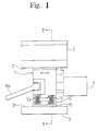
- Fig. 1 shows the sliding mechanism of a toggle block 1 which supports one end of a frame toggle plate 64 of a double toggle jaw crusher.
- the toggle block 1 supports the jaw toggle plate.
- the toggle block 1 is a steel block, divided into an upper block 11 and a lower block 12. Grooves are carved, at identical positions, into the bottom face of the upper block 11 and the top face of the lower block 12 to accomodate elastic bodies 13, 13 that expand and compress vertically.
- the elastic bodies maintain the required gap between the bottom face of the upper block 11 and the top face of the lower block 12, and keep the two bodies parallel.
- a coil-shaped or pine needle-shaped spring, a rubber body, or other material of suitable elasticity can be used as the elastic body 13. During crushing, the force of the swing jaw acting through the frame toggle plate 64 acts upward on the toggle block 1, therefore the elastic bodies 13, 13 need not be of a strength to resist the swinging force.
- An upper sliding liner 14 and a lower sliding liner 15, each of low frictional resistance, are bonded to the upper surface of the upper block 11 and the lower surface of the lower block 12, respectively. These liners facilitate the sliding action of the toggle block 1, and bear the erosion caused with sliding.
- An upper support member 2 and a lower support member 3, each made of steel, are affixed like shelves and separated by a specified distance, onto the machine frame.
- the upper support member 2 has a horizontal upper sliding face 21, and the lower support member 3 has a lower sliding face 21 that is parallel to the upper sliding face.
- the distance betweeen the two sliding faces is set to be equal to the depth of the toggle block 1.
- the elastic bodies 13, 13 are compressed to sandwich the toggle block 1 between the upper sliding face 21 and the lower sliding face 31.
- the natural tendency for the compressed elastic bodies 13, 13 is to expand, the force of which causes the upper sliding liner 14 and the lower sliding liner 15 to press and be clamped firmly against the upper sliding face 21 and the lower sliding face 31, respectively.
- a device for applying an external force is attached to the toggle block 1 to enable it to slide back and forth.
- a cylinder 4 can be connected to the back face of toggle block 1, wherein contraction and expansion of the cylinder will enable the toggle block to slide.
- the cylinder 4 is made to expand or contract, wherein the synergistic action of the sliding action of the upper and the lower sliding liners 14, 15 of low frictional resistance, and the release of the toggle block as the elastic bodies 13, 13 contract, enable the toggle block 1 to slide easily.
Landscapes
- Engineering & Computer Science (AREA)
- Mechanical Engineering (AREA)
- Food Science & Technology (AREA)
- Crushing And Grinding (AREA)
- Crushing And Pulverization Processes (AREA)
Claims (5)
- Mécanisme de coulissement de bloc basculant pour concasseur à mâchoires comprenant
un bloc basculant (1) supportant une extrémité d'un plateau basculant (64) connecté à l'autre extrémité à l'extrémité inférieure d'une mâchoire oscillante, caractérisé en ce que le bloc basculant comprend un bloc supérieur (11) et un bloc inférieur (12), reliés par un corps élastique (13), pris en sandwich entre un organe de support supérieur (2) et un organe de support inférieur (3) qui sont reliés au cadre de la machine, le bloc basculant (1) pouvant coulisser en avant et en arrière sous l'action d'une force extérieure (4). - Mécanisme de coulissement de bloc basculant pour concasseur à mâchoires selon la revendication 1, dans lequel des pièces d'écartement pour coulissement à basse résistance de friction sont reliées à la face supérieure du bloc supérieur et à la face inférieure du bloc inférieur.
- Mécanisme de coulissement de bloc basculant pour concasseur a mâchoires selon la revendication 1 ou 2, dans lequel un cylindre connecté au bloc basculant est utilisé comme moyen pour appliquer une force extérieure au bloc basculant.
- Mécanisme de coulissement de bloc basculant pour concasseur à mâchoires selon la revendication 1, 2 ou 3, dans lequel un ressort est utilisé comme corps élastique qui relie le bloc supérieur au bloc inférieur.
- Mécanisme de coulissement de bloc basculant pour concasseur à mâchoires selon la revendication 1, 2 ou 3, dans lequel un corps en caoutchouc est utilisé comme corps élastique qui relie le bloc inférieur au bloc supérieur.
Applications Claiming Priority (4)
| Application Number | Priority Date | Filing Date | Title |
|---|---|---|---|
| JP93043/94 | 1994-04-06 | ||
| JP6093043A JP2747787B2 (ja) | 1994-04-06 | 1994-04-06 | ジョ−クラッシャのトグルブロックスライド機構 |
| JP9304394 | 1994-04-06 | ||
| PCT/JP1995/000666 WO1995027562A1 (fr) | 1994-04-06 | 1995-04-06 | Mecanisme de coulissement de bloc basculant pour concasseur a machoires |
Publications (3)
| Publication Number | Publication Date |
|---|---|
| EP0701866A1 EP0701866A1 (fr) | 1996-03-20 |
| EP0701866A4 EP0701866A4 (fr) | 1996-08-14 |
| EP0701866B1 true EP0701866B1 (fr) | 1999-10-06 |
Family
ID=14071485
Family Applications (1)
| Application Number | Title | Priority Date | Filing Date |
|---|---|---|---|
| EP95914521A Expired - Lifetime EP0701866B1 (fr) | 1994-04-06 | 1995-04-06 | Mecanisme de coulissement de bloc basculant pour concasseur a machoires |
Country Status (8)
| Country | Link |
|---|---|
| EP (1) | EP0701866B1 (fr) |
| JP (1) | JP2747787B2 (fr) |
| KR (1) | KR100207155B1 (fr) |
| AT (1) | ATE185288T1 (fr) |
| AU (1) | AU682106B2 (fr) |
| DE (1) | DE69512595T2 (fr) |
| ES (1) | ES2136843T3 (fr) |
| WO (1) | WO1995027562A1 (fr) |
Families Citing this family (3)
| Publication number | Priority date | Publication date | Assignee | Title |
|---|---|---|---|---|
| JP2808236B2 (ja) * | 1994-05-17 | 1998-10-08 | コトブキ技研工業株式会社 | ジョ−クラッシャのトグルブロック位置調整方法及びその方法に用いる装置 |
| CN106732889B (zh) * | 2016-12-23 | 2019-02-12 | 奉节县可成农业发展有限公司 | 一种农业大数据用块状肥料初步全面破碎装置 |
| JP6773828B2 (ja) * | 2019-02-05 | 2020-10-21 | 株式会社アーステクニカ | ジョークラッシャ |
Family Cites Families (1)
| Publication number | Priority date | Publication date | Assignee | Title |
|---|---|---|---|---|
| AU1001270A (en) * | 1969-12-04 | 1971-07-08 | Otsuka Ferko Kabushiki Kaisha | A device for tightening a toggle block ina jaw type crusher |
-
1994
- 1994-04-06 JP JP6093043A patent/JP2747787B2/ja not_active Expired - Fee Related
-
1995
- 1995-04-06 WO PCT/JP1995/000666 patent/WO1995027562A1/fr not_active Ceased
- 1995-04-06 AU AU21475/95A patent/AU682106B2/en not_active Ceased
- 1995-04-06 AT AT95914521T patent/ATE185288T1/de active
- 1995-04-06 KR KR1019950705492A patent/KR100207155B1/ko not_active Expired - Fee Related
- 1995-04-06 EP EP95914521A patent/EP0701866B1/fr not_active Expired - Lifetime
- 1995-04-06 ES ES95914521T patent/ES2136843T3/es not_active Expired - Lifetime
- 1995-04-06 DE DE69512595T patent/DE69512595T2/de not_active Expired - Fee Related
Also Published As
| Publication number | Publication date |
|---|---|
| JPH07275724A (ja) | 1995-10-24 |
| JP2747787B2 (ja) | 1998-05-06 |
| ES2136843T3 (es) | 1999-12-01 |
| DE69512595D1 (de) | 1999-11-11 |
| DE69512595T2 (de) | 2000-05-31 |
| EP0701866A4 (fr) | 1996-08-14 |
| AU682106B2 (en) | 1997-09-18 |
| ATE185288T1 (de) | 1999-10-15 |
| KR100207155B1 (ko) | 1999-07-15 |
| KR960702771A (ko) | 1996-05-23 |
| EP0701866A1 (fr) | 1996-03-20 |
| WO1995027562A1 (fr) | 1995-10-19 |
| AU2147595A (en) | 1995-10-30 |
Similar Documents
| Publication | Publication Date | Title |
|---|---|---|
| CN1322932C (zh) | 带有液压缸过载装置的颚式破碎机 | |
| CN103842088B (zh) | 颚式破碎机 | |
| US3473744A (en) | Jaw crusher adjustment | |
| US6957786B2 (en) | Jaw crusher unit | |
| JP2808236B2 (ja) | ジョ−クラッシャのトグルブロック位置調整方法及びその方法に用いる装置 | |
| EP0701866B1 (fr) | Mecanisme de coulissement de bloc basculant pour concasseur a machoires | |
| US20040094644A1 (en) | Jaw crusher unit | |
| US5878969A (en) | Sliding mechanism for a jaw crusher toggle block | |
| JPH09511172A (ja) | 特に材料のリサイクル用に構成されたジョー付きクラッシャー | |
| JPS61181548A (ja) | ロ−ル・トレイ式粉砕機 | |
| US3386667A (en) | High frequency hydraulic actuated jaw crusher | |
| JPS63203237A (ja) | 鍛造プレス成形機械 | |
| JP2969553B2 (ja) | ジョ−クラッシャのトグルブロックの位置調整機構 | |
| JP2989196B2 (ja) | 破砕用拡開刃の拡開構造 | |
| JPS63118490A (ja) | 自動セツト調整機構を有する安全装置付破砕機 | |
| US3362322A (en) | Press | |
| JPS5834047A (ja) | 砕石機 | |
| JP2570565B2 (ja) | ジョークラッシャーのトッグルブロック固定構造 | |
| JP3691576B2 (ja) | ジョークラッシャ | |
| JPS6145881Y2 (fr) | ||
| JPS61164712A (ja) | ビレツトシヤ−の下側ワ−クホルダ− | |
| JPH0716481A (ja) | ジョークラッシャーの緊張装置 | |
| JP2589126Y2 (ja) | ジョ−クラッシャ | |
| DE3476776D1 (en) | Jaws or shells for a hydraulically driven mechanical rock-splitting apparatus | |
| JP2599048Y2 (ja) | ジョークラッシャー |
Legal Events
| Date | Code | Title | Description |
|---|---|---|---|
| PUAI | Public reference made under article 153(3) epc to a published international application that has entered the european phase |
Free format text: ORIGINAL CODE: 0009012 |
|
| 17P | Request for examination filed |
Effective date: 19951204 |
|
| AK | Designated contracting states |
Kind code of ref document: A1 Designated state(s): AT DE ES FR GB IT PT SE |
|
| A4 | Supplementary search report drawn up and despatched | ||
| AK | Designated contracting states |
Kind code of ref document: A4 Designated state(s): AT DE ES FR GB IT PT SE |
|
| GRAG | Despatch of communication of intention to grant |
Free format text: ORIGINAL CODE: EPIDOS AGRA |
|
| 17Q | First examination report despatched |
Effective date: 19981116 |
|
| GRAG | Despatch of communication of intention to grant |
Free format text: ORIGINAL CODE: EPIDOS AGRA |
|
| GRAG | Despatch of communication of intention to grant |
Free format text: ORIGINAL CODE: EPIDOS AGRA |
|
| GRAH | Despatch of communication of intention to grant a patent |
Free format text: ORIGINAL CODE: EPIDOS IGRA |
|
| GRAH | Despatch of communication of intention to grant a patent |
Free format text: ORIGINAL CODE: EPIDOS IGRA |
|
| GRAA | (expected) grant |
Free format text: ORIGINAL CODE: 0009210 |
|
| AK | Designated contracting states |
Kind code of ref document: B1 Designated state(s): AT DE ES FR GB IT PT SE |
|
| REF | Corresponds to: |
Ref document number: 185288 Country of ref document: AT Date of ref document: 19991015 Kind code of ref document: T |
|
| REF | Corresponds to: |
Ref document number: 69512595 Country of ref document: DE Date of ref document: 19991111 |
|
| REG | Reference to a national code |
Ref country code: ES Ref legal event code: FG2A Ref document number: 2136843 Country of ref document: ES Kind code of ref document: T3 |
|
| ITF | It: translation for a ep patent filed | ||
| REG | Reference to a national code |
Ref country code: PT Ref legal event code: SC4A Free format text: AVAILABILITY OF NATIONAL TRANSLATION Effective date: 19991025 |
|
| ET | Fr: translation filed | ||
| PLBE | No opposition filed within time limit |
Free format text: ORIGINAL CODE: 0009261 |
|
| STAA | Information on the status of an ep patent application or granted ep patent |
Free format text: STATUS: NO OPPOSITION FILED WITHIN TIME LIMIT |
|
| 26N | No opposition filed | ||
| PGFP | Annual fee paid to national office [announced via postgrant information from national office to epo] |
Ref country code: GB Payment date: 20010327 Year of fee payment: 7 |
|
| PGFP | Annual fee paid to national office [announced via postgrant information from national office to epo] |
Ref country code: PT Payment date: 20010406 Year of fee payment: 7 |
|
| PGFP | Annual fee paid to national office [announced via postgrant information from national office to epo] |
Ref country code: SE Payment date: 20010411 Year of fee payment: 7 |
|
| PGFP | Annual fee paid to national office [announced via postgrant information from national office to epo] |
Ref country code: FR Payment date: 20010417 Year of fee payment: 7 |
|
| PGFP | Annual fee paid to national office [announced via postgrant information from national office to epo] |
Ref country code: AT Payment date: 20010423 Year of fee payment: 7 |
|
| PGFP | Annual fee paid to national office [announced via postgrant information from national office to epo] |
Ref country code: ES Payment date: 20010514 Year of fee payment: 7 |
|
| PGFP | Annual fee paid to national office [announced via postgrant information from national office to epo] |
Ref country code: DE Payment date: 20010626 Year of fee payment: 7 |
|
| REG | Reference to a national code |
Ref country code: GB Ref legal event code: IF02 |
|
| PG25 | Lapsed in a contracting state [announced via postgrant information from national office to epo] |
Ref country code: GB Free format text: LAPSE BECAUSE OF NON-PAYMENT OF DUE FEES Effective date: 20020406 Ref country code: AT Free format text: LAPSE BECAUSE OF NON-PAYMENT OF DUE FEES Effective date: 20020406 |
|
| PG25 | Lapsed in a contracting state [announced via postgrant information from national office to epo] |
Ref country code: SE Free format text: LAPSE BECAUSE OF NON-PAYMENT OF DUE FEES Effective date: 20020407 Ref country code: ES Free format text: LAPSE BECAUSE OF NON-PAYMENT OF DUE FEES Effective date: 20020407 |
|
| PG25 | Lapsed in a contracting state [announced via postgrant information from national office to epo] |
Ref country code: PT Free format text: LAPSE BECAUSE OF NON-PAYMENT OF DUE FEES Effective date: 20021031 |
|
| PG25 | Lapsed in a contracting state [announced via postgrant information from national office to epo] |
Ref country code: DE Free format text: LAPSE BECAUSE OF NON-PAYMENT OF DUE FEES Effective date: 20021101 |
|
| EUG | Se: european patent has lapsed |
Ref document number: 95914521.0 |
|
| GBPC | Gb: european patent ceased through non-payment of renewal fee |
Effective date: 20020406 |
|
| PG25 | Lapsed in a contracting state [announced via postgrant information from national office to epo] |
Ref country code: FR Free format text: LAPSE BECAUSE OF NON-PAYMENT OF DUE FEES Effective date: 20021231 |
|
| REG | Reference to a national code |
Ref country code: PT Ref legal event code: MM4A Free format text: LAPSE DUE TO NON-PAYMENT OF FEES Effective date: 20021031 |
|
| REG | Reference to a national code |
Ref country code: FR Ref legal event code: ST |
|
| REG | Reference to a national code |
Ref country code: ES Ref legal event code: FD2A Effective date: 20030514 |
|
| PG25 | Lapsed in a contracting state [announced via postgrant information from national office to epo] |
Ref country code: IT Free format text: LAPSE BECAUSE OF NON-PAYMENT OF DUE FEES;WARNING: LAPSES OF ITALIAN PATENTS WITH EFFECTIVE DATE BEFORE 2007 MAY HAVE OCCURRED AT ANY TIME BEFORE 2007. THE CORRECT EFFECTIVE DATE MAY BE DIFFERENT FROM THE ONE RECORDED. Effective date: 20050406 |