EP0701873A1 - Installation de four comme emmagasinage temporaire, derrière un dispositif de coulée pour brames minces - Google Patents
Installation de four comme emmagasinage temporaire, derrière un dispositif de coulée pour brames minces Download PDFInfo
- Publication number
- EP0701873A1 EP0701873A1 EP95250210A EP95250210A EP0701873A1 EP 0701873 A1 EP0701873 A1 EP 0701873A1 EP 95250210 A EP95250210 A EP 95250210A EP 95250210 A EP95250210 A EP 95250210A EP 0701873 A1 EP0701873 A1 EP 0701873A1
- Authority
- EP
- European Patent Office
- Prior art keywords
- furnace system
- furnace
- transport
- rollers
- station
- Prior art date
- Legal status (The legal status is an assumption and is not a legal conclusion. Google has not performed a legal analysis and makes no representation as to the accuracy of the status listed.)
- Granted
Links
- 238000005266 casting Methods 0.000 title claims abstract description 11
- 238000012432 intermediate storage Methods 0.000 title claims abstract description 4
- 238000005096 rolling process Methods 0.000 claims abstract description 12
- 238000004804 winding Methods 0.000 claims description 32
- 238000005452 bending Methods 0.000 claims description 13
- 238000003860 storage Methods 0.000 claims description 11
- 238000007689 inspection Methods 0.000 claims description 3
- 239000000463 material Substances 0.000 abstract description 2
- 238000009434 installation Methods 0.000 abstract 6
- 230000032258 transport Effects 0.000 description 27
- 238000000034 method Methods 0.000 description 3
- 238000010276 construction Methods 0.000 description 2
- 238000005245 sintering Methods 0.000 description 2
- 230000015556 catabolic process Effects 0.000 description 1
- 238000009749 continuous casting Methods 0.000 description 1
- 230000017525 heat dissipation Effects 0.000 description 1
- 230000010354 integration Effects 0.000 description 1
- 230000007257 malfunction Effects 0.000 description 1
Images


Classifications
-
- C—CHEMISTRY; METALLURGY
- C21—METALLURGY OF IRON
- C21D—MODIFYING THE PHYSICAL STRUCTURE OF FERROUS METALS; GENERAL DEVICES FOR HEAT TREATMENT OF FERROUS OR NON-FERROUS METALS OR ALLOYS; MAKING METAL MALLEABLE, e.g. BY DECARBURISATION OR TEMPERING
- C21D9/00—Heat treatment, e.g. annealing, hardening, quenching or tempering, adapted for particular articles; Furnaces therefor
- C21D9/52—Heat treatment, e.g. annealing, hardening, quenching or tempering, adapted for particular articles; Furnaces therefor for wires; for strips ; for rods of unlimited length
- C21D9/54—Furnaces for treating strips or wire
- C21D9/68—Furnace coilers; Hot coilers
-
- B—PERFORMING OPERATIONS; TRANSPORTING
- B21—MECHANICAL METAL-WORKING WITHOUT ESSENTIALLY REMOVING MATERIAL; PUNCHING METAL
- B21B—ROLLING OF METAL
- B21B1/00—Metal-rolling methods or mills for making semi-finished products of solid or profiled cross-section; Sequence of operations in milling trains; Layout of rolling-mill plant, e.g. grouping of stands; Succession of passes or of sectional pass alternations
- B21B1/46—Metal-rolling methods or mills for making semi-finished products of solid or profiled cross-section; Sequence of operations in milling trains; Layout of rolling-mill plant, e.g. grouping of stands; Succession of passes or of sectional pass alternations for rolling metal immediately subsequent to continuous casting
Definitions
- the invention relates to a furnace system as a buffer between the thornless winding device downstream of a thin slab casting system for the strip-shaped cast strand and an unwinding device corresponding to the subsequent rolling mill, and a transport system for the wound bundles through the furnace system.
- a generic furnace system is known from German Patent 32 41 745, in particular from Figure 2.
- the problem with plants which feed continuously cast thin strip directly to a downstream rolling mill is that the casting speeds are and have to be substantially lower than the rolling speeds in the rolling mill.
- Various solutions have therefore been proposed with which a speed compensation should be made, for example by temporarily storing the band-shaped cast strand wound into bundles in a furnace system which simply creates a buffer zone between the continuous casting system and the rolling mill.
- the aim of the invention is to design a generic device in such a way that with a largely closed furnace system only a small amount Heat losses occur and as few movement elements as possible inside the system ensure low heat flow and high operational reliability.
- the integration of the winding and unwinding device in the furnace system creates the required self-contained system with low heat losses, whereby the transport device arranged below the furnace system with movable parts provided outside the furnace system significantly reduces the susceptibility to faults in parts otherwise provided inside the furnace. This ensures the required operational safety.
- the transport device consists of two coil transport carriages which can be moved independently of one another on the center beneath the furnace system and along longitudinally running rails, one transport carriage being assigned to the winding station and the other transport carriage to the unwinding station created a functionally reliable temporary storage system equipped with proven operating elements.
- the supports provided for receiving the bundles on the transport trolleys pass through the opening of the furnace system which extends parallel to the floor on the floor side, the opening being closable by flaps which can be moved away in the immediate area of the supports when the transport trolley is moved.
- the movable parts tiltes
- the proposed flaps, which close the bottom opening, ensure that extremely low heat dissipation is only possible where the flaps are moved away in the immediate vicinity of the transport trolley or the supports.
- a passage opening for desintering can be cleared when the flaps are moved away. Since sintering always occurs inside the furnace, it must be ensured that it can leave the furnace. It is advisable to design the flaps accordingly so that the oven can be self-cleaned.
- the furnace system is provided on both sides of the bottom opening outside the winding and unwinding device with prismatic supports for the bundles forming storage banks.
- the bundles are placed next to each other on these storage benches in the longitudinal direction of the furnace system and are thus temporarily stored.
- the transport carriage assigned to the unwinding station can transfer the temporarily stored bundle to the unwinding station.
- the winding station has drivable base rollers arranged within the furnace system for the band-shaped cast strand coming from the thin slab casting system, which are assigned driving and adjustable bending rollers for forming the federal government, which largely close the furnace inlet opening in the operating state.
- driving and adjustable bending rollers for forming the federal government, which largely close the furnace inlet opening in the operating state.
- Such domless winding stations are known per se.
- Such a station is now integrated into the entire furnace system, the driving and bending rollers necessary for producing the federal government being arranged in such a way that they close the furnace in the operating position and thus keep the heat flow low.
- the driving and bending rollers as a unit can be moved out of the inlet opening of the furnace system into a repair and / or inspection position and the inlet opening of the furnace system can be closed by a door when the driving and bending rollers are extended.
- the parts exposed to wear can be moved out of the overall system very quickly without heat losses occurring in the furnace; because the opening is immediately closed by the door.
- the unwinding station integrated in the furnace system also has driven bottom rollers as a support for the coil to be unwound, and a door that can be opened in the direction of the subsequent rolling mill, through which a manipulator guiding the beginning of the strip can be inserted. which can be retracted after threading this beginning into a pair of drive rollers, the door being closable except for a narrow passage opening for the band-shaped cast strand.
- Both the bottom rolls of the winding station and the unwinding station are arranged on a movable frame which can be extended across the furnace system on rails arranged below the system. This makes it possible to easily remove these parts from the furnace in order to inspect, repair or replace them.
- the invention creates a system with which the object of the present invention can be achieved, namely with simple constructional means with high operational reliability.
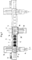
- the enclosed roller table part is marked at 8, which receives the cast strand 9, which comes from the thin slab casting plant, not shown, with or without an intermediate roughing train.
- the cast strand 9 is fed to a movable drive roller pair 11, as indicated at 10, is grasped by it and fed to the bending roller unit 12, the roller guide table 13 serving as a guide.
- the bending rollers of the bending roller unit 12 form the cast strand into a turn, which are formed into a collar on the driven base rollers 14.
- the bending roller set 12 and the driver 11 are shielded so extensively that only a small passage opening remains for the cast strand 9 to be inserted, that is to say the furnace is largely closed.
- the winding process of the federal government continues, with the driven base rollers 14 taking over the winding process to the finished bundle after the winding with the support of the movable support roller 16.
- the tape winding speed corresponds to that of the thin slab caster or, if applicable, the roughing speed.
- the last turns are wound up at a higher speed. The time difference is such that the finished bundle can be transported out of the winding station before the beginning of the next cast strand arrives.
- the complete drive and bending roller unit 11, 12 is moved back in the direction of the thin slab caster with the aid of the piston-cylinder unit 10 and separated from the system.
- the resulting opening in the furnace system is closed by the door 15, which is positioned above the bending roller set 12 during the operating state, so that the furnace temperature can be maintained.
- a transport carriage to be described later For transporting the bundle out of the winding station, a transport carriage to be described later is provided, which can be moved on rails 17 below the winding station and below the furnace system 3.
- the band end 42 of the federal government is first brought into a position below the federal government axis and fixed there. This fixation makes it easy to locate and unwind the federal government, as will be described later.
- the coil transport trolley with its support which can be raised and lowered - through the bottom opening 18 in the unwinding station - lifts the collar off and on the base rollers 14 and transports the coil out of the winding station 4.
- both the bottom of the winding station 4 and the entire furnace system 3 are closed with flaps 19, which are only briefly and automatically opened and closed by the transport trolley when the transport trolley is moved with the coil.
- the length of the furnace system (Fig. 1) between the winding device 4 and the unwinding device 5 depends on the one hand on the lateral distance between the thin slab caster and rolling mill but also on the number of storage locations required.
- the bundles 7 formed in the winding station 4 are transported directly from the transport carriage into the position of the bundle 7a or directly into the unwinding station 5 and deposited there.
- FIG. 4 also shows the transport carriage designated by 22, which has transported the collar 7 or 7a with its lifting and lowering support 23 from the winding station 4 into the storage position shown.
- the transport carriage 22 can be driven with wheels 24 on the rails 17 along the furnace system 3.
- the flaps 19 immediately in front of and behind the transport carriage 22 can be seen in FIG.
- the additional storage locations for the bundles 7 within the furnace system 3 can also be occupied; it is also conceivable, as indicated at 25 in FIG. 1, to provide an end door in the furnace system 3 through which bundles can be threaded out and threaded out of the system.
- the second possibility of threading and unthreading bundles 7 is by means of frame constructions 34 and 35 on the floor rollers 14 and 27, respectively, through opened doors 40 and 41.
- the bundle transported out of the winding station in the normal operating state is either moved directly to the unwinding station 5 by the transport carriage 22 or transported to the position 7a by the transport carriage 22 and, after being deposited on the storage benches 21, taken over by the second transport carriage 26, which is assigned to the unwinding station 5.
- This transport carriage is essentially identical to the transport carriage 22, which is assigned to the winding station and can also be moved independently of this on the rails 17.
- Figure 3 it can be seen in a cross section through the unwinding station that the trolley 26 with its flaps 19 with its liftable and lowerable support 23 for the collar 7 extends through the opening formed between the bottom rollers 27 of the unwinding station and thus the collar 7 after lowering the pad 23 places on the floor rollers 27.
- the rails 32 and 33 can be seen transversely to the furnace system 3, which allow the bottom rollers of the unwinding station and the winding station to be extended.
- the floor rollers 14 and 27 are arranged on a frame construction 34 and 35, which can be extended on the rails 32, 33 from the furnace system 3 with the aid of cylinders 36 and 37. If necessary, it is conceivable that together with the Frame 35 of the trolley 26 can be extended for revision and repair purposes.
- the frames 34, 35 are constructed in such a way that the high amount of sintering, in particular when the bundles are being unwound, can be easily removed.
Landscapes
- Chemical & Material Sciences (AREA)
- Engineering & Computer Science (AREA)
- Mechanical Engineering (AREA)
- Materials Engineering (AREA)
- Thermal Sciences (AREA)
- Crystallography & Structural Chemistry (AREA)
- Physics & Mathematics (AREA)
- Metallurgy (AREA)
- Organic Chemistry (AREA)
- Metal Rolling (AREA)
- Winding, Rewinding, Material Storage Devices (AREA)
- Heat Treatments In General, Especially Conveying And Cooling (AREA)
- Tunnel Furnaces (AREA)
- Handcart (AREA)
Applications Claiming Priority (2)
| Application Number | Priority Date | Filing Date | Title |
|---|---|---|---|
| DE4434370 | 1994-09-15 | ||
| DE4434370A DE4434370C2 (de) | 1994-09-15 | 1994-09-15 | Ofenanlage als Zwischenspeicher hinter einer Dünnbrammengießanlage |
Publications (2)
| Publication Number | Publication Date |
|---|---|
| EP0701873A1 true EP0701873A1 (fr) | 1996-03-20 |
| EP0701873B1 EP0701873B1 (fr) | 1999-03-31 |
Family
ID=6529223
Family Applications (1)
| Application Number | Title | Priority Date | Filing Date |
|---|---|---|---|
| EP95250210A Expired - Lifetime EP0701873B1 (fr) | 1994-09-15 | 1995-08-28 | Installation de four comme emmagasinage temporaire, derrière un dispositif de coulée pour brames minces |
Country Status (4)
| Country | Link |
|---|---|
| US (1) | US5823766A (fr) |
| EP (1) | EP0701873B1 (fr) |
| AT (1) | ATE178237T1 (fr) |
| DE (2) | DE4434370C2 (fr) |
Cited By (1)
| Publication number | Priority date | Publication date | Assignee | Title |
|---|---|---|---|---|
| WO1999025883A1 (fr) * | 1997-11-18 | 1999-05-27 | Thyssen Krupp Stahl Ag | Four pour caisse a rouleau |
Families Citing this family (1)
| Publication number | Priority date | Publication date | Assignee | Title |
|---|---|---|---|---|
| US8043089B2 (en) * | 1999-04-23 | 2011-10-25 | 3M Innovative Properties Company | One piece dental implant and use thereof in prostodontic and orthodontic applications |
Citations (3)
| Publication number | Priority date | Publication date | Assignee | Title |
|---|---|---|---|---|
| DE3241745A1 (de) | 1982-11-11 | 1984-05-17 | Mannesmann AG, 4000 Düsseldorf | Verfahren zum herstellen von warmgewalztem stahlband aus stranggegossenem vormaterial in unmittelbar aufeinanderfolgenden arbeitsschritten |
| DE3525457A1 (de) * | 1985-07-17 | 1987-01-29 | Mannesmann Ag | Walzwerk zur herstellung warmgewalzter stahlbaender |
| DE4121489A1 (de) * | 1991-06-26 | 1993-01-14 | Mannesmann Ag | Ofenanlage als zwischenspeicher hinter einer duennbrammengiessanlage |
Family Cites Families (1)
| Publication number | Priority date | Publication date | Assignee | Title |
|---|---|---|---|---|
| JPS63252604A (ja) * | 1987-04-08 | 1988-10-19 | Hitachi Ltd | 連鋳直結圧延方法及び装置 |
-
1994
- 1994-09-15 DE DE4434370A patent/DE4434370C2/de not_active Expired - Fee Related
-
1995
- 1995-08-28 EP EP95250210A patent/EP0701873B1/fr not_active Expired - Lifetime
- 1995-08-28 AT AT95250210T patent/ATE178237T1/de not_active IP Right Cessation
- 1995-08-28 DE DE59505488T patent/DE59505488D1/de not_active Expired - Fee Related
- 1995-09-12 US US08/529,168 patent/US5823766A/en not_active Expired - Fee Related
Patent Citations (3)
| Publication number | Priority date | Publication date | Assignee | Title |
|---|---|---|---|---|
| DE3241745A1 (de) | 1982-11-11 | 1984-05-17 | Mannesmann AG, 4000 Düsseldorf | Verfahren zum herstellen von warmgewalztem stahlband aus stranggegossenem vormaterial in unmittelbar aufeinanderfolgenden arbeitsschritten |
| DE3525457A1 (de) * | 1985-07-17 | 1987-01-29 | Mannesmann Ag | Walzwerk zur herstellung warmgewalzter stahlbaender |
| DE4121489A1 (de) * | 1991-06-26 | 1993-01-14 | Mannesmann Ag | Ofenanlage als zwischenspeicher hinter einer duennbrammengiessanlage |
Cited By (1)
| Publication number | Priority date | Publication date | Assignee | Title |
|---|---|---|---|---|
| WO1999025883A1 (fr) * | 1997-11-18 | 1999-05-27 | Thyssen Krupp Stahl Ag | Four pour caisse a rouleau |
Also Published As
| Publication number | Publication date |
|---|---|
| EP0701873B1 (fr) | 1999-03-31 |
| DE59505488D1 (de) | 1999-05-06 |
| DE4434370A1 (de) | 1996-03-21 |
| ATE178237T1 (de) | 1999-04-15 |
| DE4434370C2 (de) | 1998-05-28 |
| US5823766A (en) | 1998-10-20 |
Similar Documents
| Publication | Publication Date | Title |
|---|---|---|
| EP0925246B1 (fr) | Procede pour le transport de rouleaux vers un changeur de rouleaux | |
| DE2264788A1 (de) | Verfahren und vorrichtung zum walzen von heissen metallwerkstuecken sowie aufwickler zur anwendung beim aufwickeln von heissen metallwerkstuecken | |
| DE10138857A1 (de) | Vorrichtung zum Auf- und Abwickeln von warmgewalzten Vorbändern aus heissem Metall | |
| EP0790084A2 (fr) | Bobinoir pour bandes | |
| DE2558964A1 (de) | Vorrichtung zum foerdern von bunden von bandstahl zu einer abwickelstation | |
| CH619191A5 (fr) | ||
| EP0933147A2 (fr) | Procédé et dispositif de transfert de bobines | |
| EP0569719B1 (fr) | Système de transport de bande | |
| DE1815049B1 (de) | Vorrichtung zum Ein- und Ausbringen eines Anfahrstranges einer Stranggiessanlage | |
| DE69517798T2 (de) | Verfahren und Vorrichtung zur Übergabe gewalzter Stäbe an ein Kühlbett | |
| DE4434370C2 (de) | Ofenanlage als Zwischenspeicher hinter einer Dünnbrammengießanlage | |
| DE3030382A1 (de) | Verfahren und einrichtung zum heisswalzen von metallwerkstuecken zu baendern oder platten | |
| EP3691803B1 (fr) | Laminoir multiflexible | |
| DE2613459A1 (de) | Verfahren und anlage zur vermeidung des schrottanfalles in kontinuierlichen breitbandstrassen | |
| DE60119745T2 (de) | Anlage und verfahren zur behandlung einer formmaterialbahn | |
| DE2836480B2 (de) | Vorrichtung zum Aufnehmen und Drehen eines Bandbundes | |
| AT404803B (de) | Verfahren zur verarbeitung von gegossenen metallprodukten | |
| DE889734C (de) | Aufgabe- und Abgabevorrichtung bei Kaltwalzwerken fuer Baender mit Zugwickeltrommeln | |
| DE2340764C3 (de) | Einrichtung zum Transportieren und Lagern von schweren zu Bunden auf Spulen gewickelten Bahnen aus Metall o.dgl. | |
| AT406938B (de) | Anlage und verfahren zum herstellen von gewalztem band | |
| DE2901454A1 (de) | Foerderwagen, insbesondere bundwagen | |
| DE4109201A1 (de) | Vorrichtung zum transportieren und schopfen einer walzader | |
| DE19706054A1 (de) | Induktionsschweißeinrichtung und Arbeitsverfahren zum Verbinden mehrerer Vorbänder in einer Anlage zur Endlosherstellung von warmgewalztem Stahlband | |
| DE1960506A1 (de) | Kontinuierliches Kaltwalzwerk fuer Bandstahl | |
| DE102004012120A1 (de) | Einfädelförderband |
Legal Events
| Date | Code | Title | Description |
|---|---|---|---|
| PUAI | Public reference made under article 153(3) epc to a published international application that has entered the european phase |
Free format text: ORIGINAL CODE: 0009012 |
|
| AK | Designated contracting states |
Kind code of ref document: A1 Designated state(s): AT BE DE FR GB IT LU NL SE |
|
| 17P | Request for examination filed |
Effective date: 19960221 |
|
| 17Q | First examination report despatched |
Effective date: 19980223 |
|
| GRAG | Despatch of communication of intention to grant |
Free format text: ORIGINAL CODE: EPIDOS AGRA |
|
| GRAG | Despatch of communication of intention to grant |
Free format text: ORIGINAL CODE: EPIDOS AGRA |
|
| GRAH | Despatch of communication of intention to grant a patent |
Free format text: ORIGINAL CODE: EPIDOS IGRA |
|
| GRAH | Despatch of communication of intention to grant a patent |
Free format text: ORIGINAL CODE: EPIDOS IGRA |
|
| GRAA | (expected) grant |
Free format text: ORIGINAL CODE: 0009210 |
|
| AK | Designated contracting states |
Kind code of ref document: B1 Designated state(s): AT BE DE FR GB IT LU NL SE |
|
| REF | Corresponds to: |
Ref document number: 178237 Country of ref document: AT Date of ref document: 19990415 Kind code of ref document: T |
|
| GBT | Gb: translation of ep patent filed (gb section 77(6)(a)/1977) |
Effective date: 19990408 |
|
| REF | Corresponds to: |
Ref document number: 59505488 Country of ref document: DE Date of ref document: 19990506 |
|
| ET | Fr: translation filed | ||
| ITF | It: translation for a ep patent filed | ||
| PLBE | No opposition filed within time limit |
Free format text: ORIGINAL CODE: 0009261 |
|
| STAA | Information on the status of an ep patent application or granted ep patent |
Free format text: STATUS: NO OPPOSITION FILED WITHIN TIME LIMIT |
|
| 26N | No opposition filed | ||
| PGFP | Annual fee paid to national office [announced via postgrant information from national office to epo] |
Ref country code: LU Payment date: 20000724 Year of fee payment: 6 |
|
| PGFP | Annual fee paid to national office [announced via postgrant information from national office to epo] |
Ref country code: NL Payment date: 20000725 Year of fee payment: 6 |
|
| PGFP | Annual fee paid to national office [announced via postgrant information from national office to epo] |
Ref country code: SE Payment date: 20000726 Year of fee payment: 6 |
|
| PGFP | Annual fee paid to national office [announced via postgrant information from national office to epo] |
Ref country code: BE Payment date: 20000728 Year of fee payment: 6 |
|
| PGFP | Annual fee paid to national office [announced via postgrant information from national office to epo] |
Ref country code: GB Payment date: 20010713 Year of fee payment: 7 |
|
| PGFP | Annual fee paid to national office [announced via postgrant information from national office to epo] |
Ref country code: AT Payment date: 20010725 Year of fee payment: 7 |
|
| PGFP | Annual fee paid to national office [announced via postgrant information from national office to epo] |
Ref country code: FR Payment date: 20010801 Year of fee payment: 7 Ref country code: DE Payment date: 20010801 Year of fee payment: 7 |
|
| PG25 | Lapsed in a contracting state [announced via postgrant information from national office to epo] |
Ref country code: LU Free format text: LAPSE BECAUSE OF NON-PAYMENT OF DUE FEES Effective date: 20010828 |
|
| PG25 | Lapsed in a contracting state [announced via postgrant information from national office to epo] |
Ref country code: SE Free format text: LAPSE BECAUSE OF NON-PAYMENT OF DUE FEES Effective date: 20010829 |
|
| PG25 | Lapsed in a contracting state [announced via postgrant information from national office to epo] |
Ref country code: BE Free format text: LAPSE BECAUSE OF NON-PAYMENT OF DUE FEES Effective date: 20010831 |
|
| REG | Reference to a national code |
Ref country code: GB Ref legal event code: IF02 |
|
| BERE | Be: lapsed |
Owner name: MANNESMANN A.G. Effective date: 20010831 |
|
| PG25 | Lapsed in a contracting state [announced via postgrant information from national office to epo] |
Ref country code: NL Free format text: LAPSE BECAUSE OF NON-PAYMENT OF DUE FEES Effective date: 20020301 |
|
| EUG | Se: european patent has lapsed |
Ref document number: 95250210.2 |
|
| NLV4 | Nl: lapsed or anulled due to non-payment of the annual fee |
Effective date: 20020301 |
|
| PG25 | Lapsed in a contracting state [announced via postgrant information from national office to epo] |
Ref country code: GB Free format text: LAPSE BECAUSE OF NON-PAYMENT OF DUE FEES Effective date: 20020828 Ref country code: AT Free format text: LAPSE BECAUSE OF NON-PAYMENT OF DUE FEES Effective date: 20020828 |
|
| PG25 | Lapsed in a contracting state [announced via postgrant information from national office to epo] |
Ref country code: DE Free format text: LAPSE BECAUSE OF NON-PAYMENT OF DUE FEES Effective date: 20030301 |
|
| GBPC | Gb: european patent ceased through non-payment of renewal fee |
Effective date: 20020828 |
|
| PG25 | Lapsed in a contracting state [announced via postgrant information from national office to epo] |
Ref country code: FR Free format text: LAPSE BECAUSE OF NON-PAYMENT OF DUE FEES Effective date: 20030430 |
|
| REG | Reference to a national code |
Ref country code: FR Ref legal event code: ST |
|
| PG25 | Lapsed in a contracting state [announced via postgrant information from national office to epo] |
Ref country code: IT Free format text: LAPSE BECAUSE OF NON-PAYMENT OF DUE FEES;WARNING: LAPSES OF ITALIAN PATENTS WITH EFFECTIVE DATE BEFORE 2007 MAY HAVE OCCURRED AT ANY TIME BEFORE 2007. THE CORRECT EFFECTIVE DATE MAY BE DIFFERENT FROM THE ONE RECORDED. Effective date: 20050828 |