EP0701886A2 - Verfahren und Vorrichtung zum Hochgeschwindigkeitsschneiden von elastomerischen Werkstoffen - Google Patents
Verfahren und Vorrichtung zum Hochgeschwindigkeitsschneiden von elastomerischen Werkstoffen Download PDFInfo
- Publication number
- EP0701886A2 EP0701886A2 EP19950202274 EP95202274A EP0701886A2 EP 0701886 A2 EP0701886 A2 EP 0701886A2 EP 19950202274 EP19950202274 EP 19950202274 EP 95202274 A EP95202274 A EP 95202274A EP 0701886 A2 EP0701886 A2 EP 0701886A2
- Authority
- EP
- European Patent Office
- Prior art keywords
- shoe
- rotary blade
- cutting
- sheet
- rotary
- Prior art date
- Legal status (The legal status is an assumption and is not a legal conclusion. Google has not performed a legal analysis and makes no representation as to the accuracy of the status listed.)
- Withdrawn
Links
Images
Classifications
-
- B—PERFORMING OPERATIONS; TRANSPORTING
- B26—HAND CUTTING TOOLS; CUTTING; SEVERING
- B26D—CUTTING; DETAILS COMMON TO MACHINES FOR PERFORATING, PUNCHING, CUTTING-OUT, STAMPING-OUT OR SEVERING
- B26D1/00—Cutting through work characterised by the nature or movement of the cutting member or particular materials not otherwise provided for; Apparatus or machines therefor; Cutting members therefor
- B26D1/01—Cutting through work characterised by the nature or movement of the cutting member or particular materials not otherwise provided for; Apparatus or machines therefor; Cutting members therefor involving a cutting member which does not travel with the work
- B26D1/12—Cutting through work characterised by the nature or movement of the cutting member or particular materials not otherwise provided for; Apparatus or machines therefor; Cutting members therefor involving a cutting member which does not travel with the work having a cutting member moving about an axis
-
- B—PERFORMING OPERATIONS; TRANSPORTING
- B26—HAND CUTTING TOOLS; CUTTING; SEVERING
- B26D—CUTTING; DETAILS COMMON TO MACHINES FOR PERFORATING, PUNCHING, CUTTING-OUT, STAMPING-OUT OR SEVERING
- B26D3/00—Cutting work characterised by the nature of the cut made; Apparatus therefor
- B26D3/003—Cutting work characterised by the nature of the cut made; Apparatus therefor specially adapted for cutting rubber
-
- B—PERFORMING OPERATIONS; TRANSPORTING
- B26—HAND CUTTING TOOLS; CUTTING; SEVERING
- B26D—CUTTING; DETAILS COMMON TO MACHINES FOR PERFORATING, PUNCHING, CUTTING-OUT, STAMPING-OUT OR SEVERING
- B26D1/00—Cutting through work characterised by the nature or movement of the cutting member or particular materials not otherwise provided for; Apparatus or machines therefor; Cutting members therefor
- B26D1/01—Cutting through work characterised by the nature or movement of the cutting member or particular materials not otherwise provided for; Apparatus or machines therefor; Cutting members therefor involving a cutting member which does not travel with the work
- B26D1/12—Cutting through work characterised by the nature or movement of the cutting member or particular materials not otherwise provided for; Apparatus or machines therefor; Cutting members therefor involving a cutting member which does not travel with the work having a cutting member moving about an axis
- B26D1/14—Cutting through work characterised by the nature or movement of the cutting member or particular materials not otherwise provided for; Apparatus or machines therefor; Cutting members therefor involving a cutting member which does not travel with the work having a cutting member moving about an axis with a circular cutting member, e.g. disc cutter
- B26D1/20—Cutting through work characterised by the nature or movement of the cutting member or particular materials not otherwise provided for; Apparatus or machines therefor; Cutting members therefor involving a cutting member which does not travel with the work having a cutting member moving about an axis with a circular cutting member, e.g. disc cutter coacting with a fixed member
- B26D1/205—Cutting through work characterised by the nature or movement of the cutting member or particular materials not otherwise provided for; Apparatus or machines therefor; Cutting members therefor involving a cutting member which does not travel with the work having a cutting member moving about an axis with a circular cutting member, e.g. disc cutter coacting with a fixed member for thin material, e.g. for sheets, strips or the like
-
- B—PERFORMING OPERATIONS; TRANSPORTING
- B26—HAND CUTTING TOOLS; CUTTING; SEVERING
- B26D—CUTTING; DETAILS COMMON TO MACHINES FOR PERFORATING, PUNCHING, CUTTING-OUT, STAMPING-OUT OR SEVERING
- B26D1/00—Cutting through work characterised by the nature or movement of the cutting member or particular materials not otherwise provided for; Apparatus or machines therefor; Cutting members therefor
- B26D1/01—Cutting through work characterised by the nature or movement of the cutting member or particular materials not otherwise provided for; Apparatus or machines therefor; Cutting members therefor involving a cutting member which does not travel with the work
- B26D1/12—Cutting through work characterised by the nature or movement of the cutting member or particular materials not otherwise provided for; Apparatus or machines therefor; Cutting members therefor involving a cutting member which does not travel with the work having a cutting member moving about an axis
- B26D1/25—Cutting through work characterised by the nature or movement of the cutting member or particular materials not otherwise provided for; Apparatus or machines therefor; Cutting members therefor involving a cutting member which does not travel with the work having a cutting member moving about an axis with a non-circular cutting member
- B26D1/26—Cutting through work characterised by the nature or movement of the cutting member or particular materials not otherwise provided for; Apparatus or machines therefor; Cutting members therefor involving a cutting member which does not travel with the work having a cutting member moving about an axis with a non-circular cutting member moving about an axis substantially perpendicular to the line of cut
- B26D1/28—Cutting through work characterised by the nature or movement of the cutting member or particular materials not otherwise provided for; Apparatus or machines therefor; Cutting members therefor involving a cutting member which does not travel with the work having a cutting member moving about an axis with a non-circular cutting member moving about an axis substantially perpendicular to the line of cut and rotating continuously in one direction during cutting
- B26D1/285—Cutting through work characterised by the nature or movement of the cutting member or particular materials not otherwise provided for; Apparatus or machines therefor; Cutting members therefor involving a cutting member which does not travel with the work having a cutting member moving about an axis with a non-circular cutting member moving about an axis substantially perpendicular to the line of cut and rotating continuously in one direction during cutting for thin material, e.g. for sheets, strips or the like
-
- B—PERFORMING OPERATIONS; TRANSPORTING
- B26—HAND CUTTING TOOLS; CUTTING; SEVERING
- B26D—CUTTING; DETAILS COMMON TO MACHINES FOR PERFORATING, PUNCHING, CUTTING-OUT, STAMPING-OUT OR SEVERING
- B26D7/00—Details of apparatus for cutting, cutting-out, stamping-out, punching, perforating, or severing by means other than cutting
- B26D7/08—Means for treating work or cutting member to facilitate cutting
- B26D7/084—Means for treating work or cutting member to facilitate cutting specially adapted for cutting articles composed of at least two different materials, e.g. using cutters of different shapes
-
- B—PERFORMING OPERATIONS; TRANSPORTING
- B26—HAND CUTTING TOOLS; CUTTING; SEVERING
- B26D—CUTTING; DETAILS COMMON TO MACHINES FOR PERFORATING, PUNCHING, CUTTING-OUT, STAMPING-OUT OR SEVERING
- B26D7/00—Details of apparatus for cutting, cutting-out, stamping-out, punching, perforating, or severing by means other than cutting
- B26D7/08—Means for treating work or cutting member to facilitate cutting
- B26D7/10—Means for treating work or cutting member to facilitate cutting by heating
-
- B—PERFORMING OPERATIONS; TRANSPORTING
- B26—HAND CUTTING TOOLS; CUTTING; SEVERING
- B26D—CUTTING; DETAILS COMMON TO MACHINES FOR PERFORATING, PUNCHING, CUTTING-OUT, STAMPING-OUT OR SEVERING
- B26D7/00—Details of apparatus for cutting, cutting-out, stamping-out, punching, perforating, or severing by means other than cutting
- B26D7/26—Means for mounting or adjusting the cutting member; Means for adjusting the stroke of the cutting member
- B26D7/2614—Means for mounting the cutting member
-
- Y—GENERAL TAGGING OF NEW TECHNOLOGICAL DEVELOPMENTS; GENERAL TAGGING OF CROSS-SECTIONAL TECHNOLOGIES SPANNING OVER SEVERAL SECTIONS OF THE IPC; TECHNICAL SUBJECTS COVERED BY FORMER USPC CROSS-REFERENCE ART COLLECTIONS [XRACs] AND DIGESTS
- Y10—TECHNICAL SUBJECTS COVERED BY FORMER USPC
- Y10T—TECHNICAL SUBJECTS COVERED BY FORMER US CLASSIFICATION
- Y10T83/00—Cutting
- Y10T83/929—Tool or tool with support
- Y10T83/9319—Toothed blade or tooth therefor
-
- Y—GENERAL TAGGING OF NEW TECHNOLOGICAL DEVELOPMENTS; GENERAL TAGGING OF CROSS-SECTIONAL TECHNOLOGIES SPANNING OVER SEVERAL SECTIONS OF THE IPC; TECHNICAL SUBJECTS COVERED BY FORMER USPC CROSS-REFERENCE ART COLLECTIONS [XRACs] AND DIGESTS
- Y10—TECHNICAL SUBJECTS COVERED BY FORMER USPC
- Y10T—TECHNICAL SUBJECTS COVERED BY FORMER US CLASSIFICATION
- Y10T83/00—Cutting
- Y10T83/929—Tool or tool with support
- Y10T83/9372—Rotatable type
Definitions
- This invention pertains to the art of methods and apparatus for cutting sheet-like materials, and more specifically to methods and apparatus for cutting reinforced elastomeric fabric such as that used in the manufacture of tires.
- the present invention provides improved edge quality and precision, as well as other better and more advantageous overall results.
- the high speed rotary cutter assembly includes a rotary blade which is rotatable at operating speeds greater than 2000 rpm and preferably at 5000 revolutions per minute.
- the high speed rotary cutter assembly includes a spindle rotatably mounted in a bore of a housing.
- the spindle includes a bore with a spiral machined groove in the bore which communicates cooling air to the rotary blade and to the spindle.
- the spindle may include a cooling nozzle to propel air into a the spindle bore if further cooling is required.
- the high speed rotary cutter assembly includes a shoe having a shoe insert.
- the shoe insert cooperates with the rotary blade to provide a cutting surface for the associated elastomeric materials.
- the cutter assembly includes an adjustment means for precision adjustment of the shoe insert relative to the blade.
- the adjustment means comprises a slide which cooperates with a frame upon which the shoe and shoe insert are mounted, and the housing containing the spindle and rotary blade, to precisely locate the shoe insert relative to the rotary blade.
- the shoe insert has a top surface which is in the same plane as a top surface of the shoe.
- the shoe insert includes a grooved cutting surface for reduced surface contact.
- the cross-sectional shape of the shoe insert may resemble the cross-sectional shape of an I beam.
- the rotary blade has an operating rotational speed S with S being greater than 2000 rpm.
- the rotary blade also has lobes L with the number of lobes being between 4 and 40.
- Each of the lobes L of the rotary blade has an attack angle AA between 0 degrees and 20 degrees.
- the configuration of lobes include an attack surface 146 and trailing surface separated by peak.
- the attack surface makes an attack angle AA with a plane P-P containing the sheet of elastomeric material as shown in Fig. 9.
- the attack angle is preferably between 0 degrees and 20 degrees.
- the trailing surface makes a trailing angle TS with the attack surface 146 of about 110 degrees.
- a method for high speed rotary cutting of a sheet of elastomeric material comprises the steps of rotating a rotary blade at a rotational speed S greater than 2000 rpm and passing a sheet of elastomeric materials past the rotary blade so that the rotary blade cuts the sheet of elastomeric material.
- the elastomeric material is supported on a shoe and a shoe insert with the top surface of the shoe being in a shoe plane and the top surface of the shoe insert also being in the shoe plane.
- the method further includes the step of cooling the blade by communicating air through a spindle bore to the blade.
- a high speed rotary cutter assembly for cutting a sheet of elastomeric material comprising a rotary blade having an operating rotational speed S with S being greater than 2000 rpm, said rotary blade also having a plurality of lobes, one of said lobes of said rotary blade having an attack surface and a trailing surface separated by a peak, said attack surface making an attack angle AA with a plane containing said sheet of elastomeric material, said attack angle AA being between 0 degrees and 20 degrees, said trailing surface making a trailing angle TS with said attack surface, said trailing angle TS being about 110 degrees.
- One advantage of the present invention is the provision of a new and improved rotary cutter apparatus and method which can be used to produce high quality cut elastomeric materials.
- Another advantage of the invention is the provision of a method and apparatus for rotary cutting sheets of elastomeric materials which improves the edge quality and edge variation of the cut sheets.
- a still further advantage of the invention is the provision of a rotary cutting assembly which operates at higher speeds than prior art apparatus.
- Still another advantage of the invention is the provision of a method and apparatus of quickly, easily, and accurately replacing worn shoe inserts and shoes without the need for multiple adjustments of the shoe, shoe insert and blade.
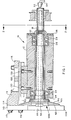
- FIG 1 shows a cross-sectional view of an inventive rotary cutter assembly 10.
- the assembly 10 includes a housing 12 and a spindle 18.
- the spindle 18 is rotatably suspended within the housing 12 by bearings 24,26,28.
- the bearings 24,26,28 are precision, preloaded angular contact ball bearings suitable for high speed applications.
- the rotary cutter assembly 10 can operate at speeds as high as 7500 rpm.
- the bearings 24,26,28 are permanently prelubricated to facilitate low maintenance operation.
- the housing 12 has a first end 34 and a second end 36. At the first end 34 of the housing 12 is a labyrinth seal 42.
- the labyrinth seal 42 is a non-contact seal which is helpful for keeping contaminates out of the assembly 10 and retaining lubricating fluid within.
- the non-contact design reduces friction, heat build up and drive torque requirements.
- the spindle 18 includes a spindle bore 46.
- the spindle bore 46 may have a spiral machined groove which is helpful in providing cooling of the spindle 18 and a rotary blade 50.
- the cooling nozzle 52 may be connected to an air hose 54 in communication with an air supply such as factory air at 80 psi.
- One type of cooling nozzle 52 which is believed to be effective would be that manufactured by Transair.
- the innovative rotary blade 50 is shown.
- the rotary blade 50 is affixedly mounted to a first end 56 of the spindle 18 and rotates therewith.
- the rotary blade 50 is preferably manufactured of tungsten-carbide and is coated with a non-stick plasma coating such as B4N.
- One important feature of the innovative rotary blade 50 is its cross-sectional shape, as illustrated in Figs 1,3,6 and 7 .
- the rotary blade 50 has a generally planar cutting surface 62 and generally planar tapered back surface 66.
- the cutting surface 62 lies generally in a cutting surface plane 70 and the back surface 66 lies generally in a back surface plane 68.
- the back surface plane 68 makes an angle ⁇ with the cutting surface plane 70.
- the angle ⁇ is between 10 degrees and 90 degrees and is preferably about 25 degrees.
- This blade 50 provides a clean cut and minimizes abrasion of the cut material.
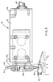
- a sheet of reinforced elastomeric material 80 shown diagrammatically in dash dot dot lines is supported on an upper pan P, which has an edge along which a shoe 86 carried by the rotary cutter assembly is moved across the material a distance of about 120 inches (47.24 cm) for the application shown.
- the traversing speed may be 400 feet per minute (122 m/min.).
- the shoe moves across the sheet of elastomeric material 80, it lifts the sheet from the position A shown in Fig 3 to the position B.
- a trailing edge 82 will drop to a lower pan P2 as shown in Fig 2 . With the tapered blade 50 there will be a minimum of abrasion of the edge 82.
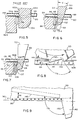
- a prior art rotary blade is shown.
- the cutting surface 62A of the prior art rotary blade 50A is generally parallel to the back surface 66A.
- the wide blade 50A also contacts the trailing edge 82 of the sheet of elastomeric material 80 causing undesirable abrasion of the edge 82.
- FIG. 6 With reference to Figs 6 and 7 , the innovative shoe insert design of the invention is shown.
- the associated sheet of reinforced elastomeric material 80 rests upon a top surface 84 of a shoe 86.
- a shoe insert 90,90B is affixed to the shoe 86.
- a prior art shoe insert 90A is shown which was recessed slightly below the top surface 84A of the shoe 86A.
- a top surface 90A of the prior art shoe insert was 0.030 inches (0.0762 cm.) beneath the top surface 84A of the shoe 86A.
- this offset required the elastomeric material 80 to deflect slightly at the point of cutting.
- the position of the insert 90A below the top surface 84A causes reinforcing wires 98 to be cut at an angle. This results in sharp chisel cut ends 99 which are not desirable in the building of tires.
- the top surface 96 of the innovative shoe inserts 90,90B lie in the same plane as the top surface 84 of the shoe 86. This orientation has provided for cutting the wires 98 squarely so that the ends are blunt and will not cut other components in the manufacture of tires.
- the shoe insert 90 is mounted on the shoe 86 and a cutting surface 100 is recessed with a groove 102 for reducing surface contact between the cut trailing edge 82 and the insert providing relief so that the heat generated will be minimized and there is no problem with objectionable smearing and formation of crumbs.
- the shoe insert 90B shown in Figs 1,2,7 and 8 has a cross section of an I beam with grooves 104 and 105 in opposing surfaces and cutting edges 106,107,108 and 109.
- the insert 90B may be fastened to the shoe 86 by suitable fasteners positioned over the grooves 104 or 105 at the ends of the insert.
- socket head button cap screws 112,113 are threaded in the housing to overlap ends of the insert in the grooves 104.
- the insert 90B with an I beam cross section may be rotated and turned over to provide four cutting edges 106,107,108 and 109 with one insert.
- the length of the inserts 90 and 90B need not be longer than that which is necessary to cut the reinforcing wires 98.
- the shoe insert 90 is preferably coated with titanium nitrate for hardness.
- one important feature of the innovative rotary cutter assembly 10 is the ability to quickly and accurately change worn shoe inserts 90 and 90B.
- Prior art cutters required separate adjustments for the gap between the rotary blade 50 and the shoe insert 90, as well as adjustment for the cant angle of the blade and shoe insert. The number and complexity of these adjustments has resulted in a time consuming setup operation. Whenever a prior art shoe insert 90 was worn, the rotary cutter assembly 10 had to be shut down for an extended period of time while the changes were made. The change was complex enough that setup specialists were required. An improper setup could damage the rotary blade 50 which was relatively expensive.
- the innovative rotary cutter assembly 10 has several features which work together to make the replacement of a shoe 86 or shoe insert 90B not only quick and easy but highly accurate.
- the housing 12 is precision machined for parallelism between the rotary blade 50 and the shoe insert 90B.
- the shoe 86 has been designed in a "quick connect" manner so that it can be easily removed. This eliminates the need for a shoe cant angle, commonly used in the prior art to compensate for bent shoes.
- the quick connect features include a frame 111 which has a first end 114 to which the shoe 86 is attached by cap screws 115 and 116.
- a second end 118 of the frame 111 includes a precision dovetail slide 120 which is mounted on the housing 12.
- the slide 120 is secured to the housing two mounting screws 130.
- a gib lock 132 includes at least two gib lock screws 133.
- the frame 111 moved away from the housing 12 on the slide 120 and the worn shoe insert 90B rotated or replaced by a new shoe insert by removing the cap screws 112 and 113.
- a shim (not shown) may be inserted between the shoe insert 90B and the rotary blade 50 to provide the desired clearance.
- the frame 111, shoe 86, and shoe insert 90B assembly may then be secured in place by the gib lock 132 and gib lock screws 132.
- the complete shoe assembly including the frame 111, shoe 86 including the shoe insert 90B may be replaced by a new shoe assembly.
- the innovative rotary cutter assembly 10 is ready to begin cutting sheets of elastomeric materials.
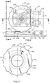
- the rotary blade 50 features a plurality of lobes 140.
- the number of lobes 140 can vary between 4 and 40 and is 16 for this embodiment.
- the innovative blade 50 incorporates an attack surface 146 which is not symmetrical about the peak 144 and trailing surface 150. Instead, the trailing surface 150 has been cut more sharply, providing relief to ensure that the cut elastomeric material does not rub and/or possibly hang up on any contact surfaces.
- the blade 50 is shown schematically in more detail with relation to the shoe 86, shoe insert 90B and the reinforced sheet of elastomeric material 80.
- the attack surface 146 of each blade 50 is disposed at an attack angle AA of preferably 0 degrees to 20 degrees and in the embodiment shown is about 8 degrees.
- the trailing surface 150 is at an angle TS of about 110 degrees to the attack surface 146.
- the angle TS is between 100 degrees and 140 degrees.
- the configuration of the innovative lobe 140 is shown as it cuts the sheet of elastomeric material 80.
- the speed of rotation of the blade 50 is increased the speed at which the rotary cutter assembly 10 is moveable across the sheet of reinforced elastomeric material 80 may be increased.
- the number of lobes 140 may be decreased. These parameters depend on the number of reinforcing wires 98 because it is desirable that each of the wires is cut by one of the lobes 140.
Landscapes
- Life Sciences & Earth Sciences (AREA)
- Forests & Forestry (AREA)
- Engineering & Computer Science (AREA)
- Mechanical Engineering (AREA)
- Physics & Mathematics (AREA)
- Optics & Photonics (AREA)
- Processing And Handling Of Plastics And Other Materials For Molding In General (AREA)
- Treatment Of Fiber Materials (AREA)
- Tyre Moulding (AREA)
- Perforating, Stamping-Out Or Severing By Means Other Than Cutting (AREA)
Applications Claiming Priority (2)
| Application Number | Priority Date | Filing Date | Title |
|---|---|---|---|
| US29885194A | 1994-08-31 | 1994-08-31 | |
| US298851 | 1994-08-31 |
Publications (2)
| Publication Number | Publication Date |
|---|---|
| EP0701886A2 true EP0701886A2 (de) | 1996-03-20 |
| EP0701886A3 EP0701886A3 (de) | 1996-09-04 |
Family
ID=23152249
Family Applications (1)
| Application Number | Title | Priority Date | Filing Date |
|---|---|---|---|
| EP19950202274 Withdrawn EP0701886A3 (de) | 1994-08-31 | 1995-08-23 | Verfahren und Vorrichtung zum Hochgeschwindigkeitsschneiden von elastomerischen Werkstoffen |
Country Status (11)
| Country | Link |
|---|---|
| US (1) | US5887506A (de) |
| EP (1) | EP0701886A3 (de) |
| JP (1) | JPH0871984A (de) |
| KR (1) | KR100364935B1 (de) |
| CN (1) | CN1057953C (de) |
| AU (1) | AU690306B2 (de) |
| BR (1) | BR9503770A (de) |
| CA (1) | CA2145321A1 (de) |
| TR (1) | TR199501052A2 (de) |
| TW (1) | TW355156B (de) |
| ZA (1) | ZA956884B (de) |
Cited By (3)
| Publication number | Priority date | Publication date | Assignee | Title |
|---|---|---|---|---|
| EP0850732A1 (de) * | 1996-12-24 | 1998-07-01 | Continental Aktiengesellschaft | Verfahren und Vorrichtung zum Ablängen eines unvulkanisierten Kautschukprofiles mittels einer Schneide |
| WO2008003819A1 (en) * | 2006-07-05 | 2008-01-10 | Fortecta Finland Ltd | Tyre cutting device, method for cutting the side wall of a tyre and use of a cutting device |
| US11370128B2 (en) | 2015-09-01 | 2022-06-28 | Berkshire Grey Operating Company, Inc. | Systems and methods for providing dynamic robotic control systems |
Families Citing this family (12)
| Publication number | Priority date | Publication date | Assignee | Title |
|---|---|---|---|---|
| EP1282488A1 (de) * | 2000-05-19 | 2003-02-12 | Pirelli Pneumatici S.p.A. | Vorrichtung zum automatischen schneiden von elastomeren materialien |
| US6444070B1 (en) * | 2000-11-29 | 2002-09-03 | The Goodyear Tire & Rubber Company | Method of building a tire having a segmented belt |
| US6692424B2 (en) * | 2001-08-01 | 2004-02-17 | Gammerler Corporation | Rotary trimmer apparatus and method |
| JP5167692B2 (ja) * | 2007-05-22 | 2013-03-21 | 吉泉産業株式会社 | 食材スライス装置 |
| CN101856825B (zh) * | 2010-05-20 | 2011-10-26 | 安庆市恒昌机械制造有限责任公司 | 一次性卫生用品生产线上的弹性材料切断转横装置 |
| CN101898367A (zh) * | 2010-07-20 | 2010-12-01 | 江苏瑞泰科技有限公司 | 带有冷却装置的切刀 |
| CN102241023B (zh) * | 2010-12-30 | 2013-04-17 | 杭州爱科科技有限公司 | 高速精密切割机 |
| CN103004941A (zh) * | 2012-12-04 | 2013-04-03 | 苏州喜福瑞农业科技有限公司 | 一种新型河蟹剥壳设备切割刀片 |
| JP6236855B2 (ja) * | 2013-04-26 | 2017-11-29 | 横浜ゴム株式会社 | タイヤの製造方法 |
| CN106944942B (zh) * | 2017-04-28 | 2019-04-05 | 赵永兴 | 一种管子台虎钳 |
| CN109079576B (zh) * | 2018-09-29 | 2021-01-08 | 北京航空航天大学 | 一种分离超高速切削高压冷却润滑方法 |
| CN113829455B (zh) * | 2021-10-08 | 2022-08-26 | 南京海强机械刀具有限公司 | 一种硬质合金涂层新型长材刨片机刀片 |
Family Cites Families (29)
| Publication number | Priority date | Publication date | Assignee | Title |
|---|---|---|---|---|
| US299142A (en) * | 1884-05-27 | James hilton | ||
| FR1536978A (fr) * | 1900-01-01 | Scie circulaire à lames multiples | ||
| US640279A (en) * | 1898-12-27 | 1900-01-02 | William M Dickerson | Veneer-saw. |
| US1914528A (en) * | 1929-12-31 | 1933-06-20 | Dunlop Tire & Rubber Corp | Cutting fork |
| US1874750A (en) * | 1931-08-22 | 1932-08-30 | Seiberling Rubber Co | Bias cutting machine |
| US3072004A (en) * | 1959-07-31 | 1963-01-08 | Armstrong Rubber Co | Severing apparatus |
| US3706252A (en) * | 1970-07-17 | 1972-12-19 | Harris Intertype Corp | Book cut-off saw |
| DE2052361A1 (en) * | 1970-10-24 | 1972-04-27 | Paul Troester, Maschinenfabrik, 3000 Hannover-Wülfel | Cooling system for knife blades - cutting plastic or rubber webs, cords |
| US3757618A (en) * | 1971-10-01 | 1973-09-11 | Goodrich Co B F | Fabric cutting |
| US3762259A (en) * | 1972-01-03 | 1973-10-02 | Goodrich Co B F | Fabric cutting apparatus |
| US3876266A (en) * | 1972-06-30 | 1975-04-08 | Heim Universal Corp | Preloaded anti-friction bearing assembly |
| US3848501A (en) * | 1973-07-20 | 1974-11-19 | Goodrich Co B F | Fabric cutting |
| US3918778A (en) * | 1974-06-05 | 1975-11-11 | Sperry Rand Corp | Dynamically balanced bearing assembly |
| JPS55120927A (en) * | 1979-03-07 | 1980-09-17 | Tani Seikiyo Kk | Circular saw with guide groove cut in inside surface, and device using the same |
| SU821087A1 (ru) * | 1979-04-25 | 1981-04-15 | Mikhalkin Anatolij | Дисковой нож |
| US4382397A (en) * | 1980-12-11 | 1983-05-10 | Torre Robert P De | Shear wheel for cutting fabric |
| US4406201A (en) * | 1981-08-24 | 1983-09-27 | The B. F. Goodrich Company | Fabric cutting |
| US4414874A (en) * | 1981-08-24 | 1983-11-15 | The B. F. Goodrich Company | Fabric cutting |
| IT1210843B (it) * | 1982-01-14 | 1989-09-29 | Leptons Italia Srl | Taglierina a rullo e suo modo di funzionamento. |
| DE3220967A1 (de) * | 1982-06-03 | 1983-12-08 | Chi-Ming Kaohsiung Taiwan Chen | Verfahren zum kuehlen von kreissaegeblaettern und kreissaege hierzu |
| DE3310166A1 (de) * | 1983-03-21 | 1984-09-27 | Günter 3061 Ahnsen Schilling | Handschneidemaschine, insbesondere zum beschneiden von tapetenraendern |
| DE3769218D1 (de) * | 1986-06-11 | 1991-05-16 | Nikken Tool Co Ltd | Bohrvorrichtung. |
| DE3719721C3 (de) * | 1987-06-12 | 1996-10-17 | Gaemmerler Hagen | Schneidmesser für Rotationsschneidanlagen für Papier |
| US4901929A (en) * | 1989-05-08 | 1990-02-20 | Barclay Randel L | Rotary shearing wheel with individually replaceable cutting segments |
| DE9002050U1 (de) * | 1990-02-21 | 1990-05-10 | Cedima Diamantwerkzeug- und Maschinenhandelsgesellschaft mbH, 3100 Celle | Schneidvorrichtung mit Kühlwasserzufuhr zu einem Sägeblatt |
| JPH0722883B2 (ja) * | 1990-11-28 | 1995-03-15 | 三ツ星ベルト株式会社 | エンドレスベルトの偏倚防止装置及び該装置を用いたベルト加工装置 |
| US5131971A (en) * | 1991-01-14 | 1992-07-21 | Elia Gerardo P | Apparatus for making a reinforced fabric from a ribbon of uncured elastomeric material |
| US5118256A (en) * | 1991-04-29 | 1992-06-02 | United Technologies Corporation | Blade retention apparatus with elastomeric preload |
| JPH04137811U (ja) * | 1991-06-19 | 1992-12-22 | 有限会社勝製作所 | ストランドに於ける冷却付カツターのペレツト製造機 |
-
1994
- 1994-08-23 BR BR9503770A patent/BR9503770A/pt not_active Application Discontinuation
-
1995
- 1995-03-23 CA CA 2145321 patent/CA2145321A1/en not_active Abandoned
- 1995-07-06 TW TW084106957A patent/TW355156B/zh active
- 1995-08-18 ZA ZA956884A patent/ZA956884B/xx unknown
- 1995-08-23 EP EP19950202274 patent/EP0701886A3/de not_active Withdrawn
- 1995-08-23 JP JP21385895A patent/JPH0871984A/ja active Pending
- 1995-08-24 TR TR95/01052A patent/TR199501052A2/xx unknown
- 1995-08-30 AU AU30353/95A patent/AU690306B2/en not_active Ceased
- 1995-08-30 KR KR1019950027525A patent/KR100364935B1/ko not_active Expired - Fee Related
- 1995-08-30 CN CN95109529A patent/CN1057953C/zh not_active Expired - Fee Related
-
1996
- 1996-10-10 US US08/728,188 patent/US5887506A/en not_active Expired - Fee Related
Non-Patent Citations (1)
| Title |
|---|
| None |
Cited By (4)
| Publication number | Priority date | Publication date | Assignee | Title |
|---|---|---|---|---|
| EP0850732A1 (de) * | 1996-12-24 | 1998-07-01 | Continental Aktiengesellschaft | Verfahren und Vorrichtung zum Ablängen eines unvulkanisierten Kautschukprofiles mittels einer Schneide |
| US6098511A (en) * | 1996-12-24 | 2000-08-08 | Continental Aktiengesellschaft | Method for cutting to length an unvulcanized rubber strip member by a cutting edge |
| WO2008003819A1 (en) * | 2006-07-05 | 2008-01-10 | Fortecta Finland Ltd | Tyre cutting device, method for cutting the side wall of a tyre and use of a cutting device |
| US11370128B2 (en) | 2015-09-01 | 2022-06-28 | Berkshire Grey Operating Company, Inc. | Systems and methods for providing dynamic robotic control systems |
Also Published As
| Publication number | Publication date |
|---|---|
| TW355156B (en) | 1999-04-01 |
| CN1123214A (zh) | 1996-05-29 |
| CA2145321A1 (en) | 1996-03-01 |
| TR199501052A2 (tr) | 1996-06-21 |
| KR960007118A (ko) | 1996-03-22 |
| CN1057953C (zh) | 2000-11-01 |
| KR100364935B1 (ko) | 2003-03-06 |
| JPH0871984A (ja) | 1996-03-19 |
| US5887506A (en) | 1999-03-30 |
| AU3035395A (en) | 1996-03-14 |
| ZA956884B (en) | 1996-03-25 |
| BR9503770A (pt) | 1996-04-16 |
| AU690306B2 (en) | 1998-04-23 |
| EP0701886A3 (de) | 1996-09-04 |
Similar Documents
| Publication | Publication Date | Title |
|---|---|---|
| EP0701886A2 (de) | Verfahren und Vorrichtung zum Hochgeschwindigkeitsschneiden von elastomerischen Werkstoffen | |
| US5090281A (en) | Slitting apparatus for corrugated paperboard and the like | |
| US4608895A (en) | Rotary die cutting | |
| EP0505508B1 (de) | Längsschneideeinrichtung für wellpappe u.dgl. | |
| EP0318174A2 (de) | Rotierende Schneidvorrichtung | |
| US8931378B2 (en) | Method and apparatus for dry lubrication of a thin slitting blade | |
| JP2005532183A (ja) | ウェブ材料切断用ロータリー装置 | |
| US2646726A (en) | Apparatus for trimming and notching signatures | |
| US6692424B2 (en) | Rotary trimmer apparatus and method | |
| US4517872A (en) | Controlled depth cutting method and apparatus | |
| US3353460A (en) | Apparatus for working sheet material | |
| US6217262B1 (en) | Edge milling cutter with cutter inserts | |
| US6244151B1 (en) | Apparatus for adjusting cutting bar | |
| EP0108356A1 (de) | Papierschneidvorrichtung | |
| US3691898A (en) | Edge burr removal apparatus | |
| JP2922221B2 (ja) | シート状物切断装置 | |
| US7614332B2 (en) | Carpet beveller | |
| US7901271B2 (en) | Shimless dual arbor scrap chopper | |
| US8783150B2 (en) | Device for trimming a print product | |
| EP0516706B1 (de) | Führung für sägebänder | |
| JPH05212695A (ja) | ガイダー付ツーピーススリッターナイフ | |
| US7083503B2 (en) | Method for sharpening the knife of a rotary trimmer and a rotary trimmer for realizing the method | |
| JPS60180708A (ja) | 帯板のサイドトリミング装置 | |
| CN121061949A (zh) | 一种膜材料加工用裁剪设备 | |
| FI69261C (fi) | Sfaeriskt maongbladigt verktyg |
Legal Events
| Date | Code | Title | Description |
|---|---|---|---|
| PUAI | Public reference made under article 153(3) epc to a published international application that has entered the european phase |
Free format text: ORIGINAL CODE: 0009012 |
|
| 17P | Request for examination filed |
Effective date: 19950823 |
|
| AK | Designated contracting states |
Kind code of ref document: A2 Designated state(s): AT DE ES FR GB IT |
|
| PUAL | Search report despatched |
Free format text: ORIGINAL CODE: 0009013 |
|
| AK | Designated contracting states |
Kind code of ref document: A3 Designated state(s): AT DE ES FR GB IT |
|
| 17Q | First examination report despatched |
Effective date: 20000406 |
|
| STAA | Information on the status of an ep patent application or granted ep patent |
Free format text: STATUS: THE APPLICATION IS DEEMED TO BE WITHDRAWN |
|
| 18D | Application deemed to be withdrawn |
Effective date: 20030307 |