EP0701893B1 - Vorrichtung und Verfahren zur Herstellung einer mit langen Fasern verstärkten Harzstruktur - Google Patents
Vorrichtung und Verfahren zur Herstellung einer mit langen Fasern verstärkten Harzstruktur Download PDFInfo
- Publication number
- EP0701893B1 EP0701893B1 EP95306331A EP95306331A EP0701893B1 EP 0701893 B1 EP0701893 B1 EP 0701893B1 EP 95306331 A EP95306331 A EP 95306331A EP 95306331 A EP95306331 A EP 95306331A EP 0701893 B1 EP0701893 B1 EP 0701893B1
- Authority
- EP
- European Patent Office
- Prior art keywords
- fiber bundle
- resin
- rollers
- impregnated
- continuous fiber
- Prior art date
- Legal status (The legal status is an assumption and is not a legal conclusion. Google has not performed a legal analysis and makes no representation as to the accuracy of the status listed.)
- Expired - Lifetime
Links
- 239000000835 fiber Substances 0.000 title claims description 118
- 229920005989 resin Polymers 0.000 title claims description 65
- 239000011347 resin Substances 0.000 title claims description 65
- 238000004519 manufacturing process Methods 0.000 title claims description 21
- 238000000034 method Methods 0.000 title description 13
- 238000007493 shaping process Methods 0.000 claims description 49
- 238000005520 cutting process Methods 0.000 claims description 16
- 238000005470 impregnation Methods 0.000 claims description 9
- 239000012467 final product Substances 0.000 claims description 8
- 239000002826 coolant Substances 0.000 claims description 3
- 238000010438 heat treatment Methods 0.000 claims description 2
- 239000008188 pellet Substances 0.000 description 17
- 229920005992 thermoplastic resin Polymers 0.000 description 15
- 239000000047 product Substances 0.000 description 8
- 239000003365 glass fiber Substances 0.000 description 5
- 150000001247 metal acetylides Chemical class 0.000 description 5
- -1 polyethylene Polymers 0.000 description 5
- 239000012783 reinforcing fiber Substances 0.000 description 4
- 238000002845 discoloration Methods 0.000 description 3
- 230000000694 effects Effects 0.000 description 3
- 239000004743 Polypropylene Substances 0.000 description 2
- PPBRXRYQALVLMV-UHFFFAOYSA-N Styrene Chemical compound C=CC1=CC=CC=C1 PPBRXRYQALVLMV-UHFFFAOYSA-N 0.000 description 2
- 239000003795 chemical substances by application Substances 0.000 description 2
- 238000010586 diagram Methods 0.000 description 2
- 239000004615 ingredient Substances 0.000 description 2
- 239000002184 metal Substances 0.000 description 2
- 229910052751 metal Inorganic materials 0.000 description 2
- 229920001155 polypropylene Polymers 0.000 description 2
- 238000000926 separation method Methods 0.000 description 2
- NLHHRLWOUZZQLW-UHFFFAOYSA-N Acrylonitrile Chemical compound C=CC#N NLHHRLWOUZZQLW-UHFFFAOYSA-N 0.000 description 1
- 108010053481 Antifreeze Proteins Proteins 0.000 description 1
- 229920000049 Carbon (fiber) Polymers 0.000 description 1
- VYZAMTAEIAYCRO-UHFFFAOYSA-N Chromium Chemical compound [Cr] VYZAMTAEIAYCRO-UHFFFAOYSA-N 0.000 description 1
- JHWNWJKBPDFINM-UHFFFAOYSA-N Laurolactam Chemical compound O=C1CCCCCCCCCCCN1 JHWNWJKBPDFINM-UHFFFAOYSA-N 0.000 description 1
- 229920000571 Nylon 11 Polymers 0.000 description 1
- 229920000299 Nylon 12 Polymers 0.000 description 1
- 229920002292 Nylon 6 Polymers 0.000 description 1
- 229920000305 Nylon 6,10 Polymers 0.000 description 1
- 229920002302 Nylon 6,6 Polymers 0.000 description 1
- 229920000572 Nylon 6/12 Polymers 0.000 description 1
- 239000004952 Polyamide Substances 0.000 description 1
- 229920002614 Polyether block amide Polymers 0.000 description 1
- 239000004698 Polyethylene Substances 0.000 description 1
- 239000004721 Polyphenylene oxide Substances 0.000 description 1
- 239000004734 Polyphenylene sulfide Substances 0.000 description 1
- 239000004433 Thermoplastic polyurethane Substances 0.000 description 1
- 239000006096 absorbing agent Substances 0.000 description 1
- 239000003963 antioxidant agent Substances 0.000 description 1
- 235000006708 antioxidants Nutrition 0.000 description 1
- 239000004760 aramid Substances 0.000 description 1
- 229920003235 aromatic polyamide Polymers 0.000 description 1
- 239000011230 binding agent Substances 0.000 description 1
- 230000015572 biosynthetic process Effects 0.000 description 1
- 239000004917 carbon fiber Substances 0.000 description 1
- 229910052804 chromium Inorganic materials 0.000 description 1
- 239000011651 chromium Substances 0.000 description 1
- 239000003086 colorant Substances 0.000 description 1
- 230000000052 comparative effect Effects 0.000 description 1
- 238000000748 compression moulding Methods 0.000 description 1
- 239000000356 contaminant Substances 0.000 description 1
- 238000011109 contamination Methods 0.000 description 1
- 230000005611 electricity Effects 0.000 description 1
- 238000001125 extrusion Methods 0.000 description 1
- 238000005562 fading Methods 0.000 description 1
- 238000004079 fireproofing Methods 0.000 description 1
- 239000003063 flame retardant Substances 0.000 description 1
- 239000011521 glass Substances 0.000 description 1
- 238000001746 injection moulding Methods 0.000 description 1
- 239000011256 inorganic filler Substances 0.000 description 1
- 229910003475 inorganic filler Inorganic materials 0.000 description 1
- 238000002844 melting Methods 0.000 description 1
- 230000008018 melting Effects 0.000 description 1
- 239000000203 mixture Substances 0.000 description 1
- 239000012766 organic filler Substances 0.000 description 1
- 229940095674 pellet product Drugs 0.000 description 1
- 239000004014 plasticizer Substances 0.000 description 1
- 229920001643 poly(ether ketone) Polymers 0.000 description 1
- 229920002492 poly(sulfone) Polymers 0.000 description 1
- 229920002647 polyamide Polymers 0.000 description 1
- 229920001707 polybutylene terephthalate Polymers 0.000 description 1
- 239000004417 polycarbonate Substances 0.000 description 1
- 229920000515 polycarbonate Polymers 0.000 description 1
- 229920000728 polyester Polymers 0.000 description 1
- 229920001601 polyetherimide Polymers 0.000 description 1
- 229920000573 polyethylene Polymers 0.000 description 1
- 229920000139 polyethylene terephthalate Polymers 0.000 description 1
- 239000005020 polyethylene terephthalate Substances 0.000 description 1
- 229920000098 polyolefin Polymers 0.000 description 1
- 229920006324 polyoxymethylene Polymers 0.000 description 1
- 229920006380 polyphenylene oxide Polymers 0.000 description 1
- 229920000069 polyphenylene sulfide Polymers 0.000 description 1
- 230000002035 prolonged effect Effects 0.000 description 1
- 230000001737 promoting effect Effects 0.000 description 1
- 230000003068 static effect Effects 0.000 description 1
- 239000012756 surface treatment agent Substances 0.000 description 1
- 229920002803 thermoplastic polyurethane Polymers 0.000 description 1
- XLYOFNOQVPJJNP-UHFFFAOYSA-N water Substances O XLYOFNOQVPJJNP-UHFFFAOYSA-N 0.000 description 1
Images


Classifications
-
- B—PERFORMING OPERATIONS; TRANSPORTING
- B29—WORKING OF PLASTICS; WORKING OF SUBSTANCES IN A PLASTIC STATE IN GENERAL
- B29C—SHAPING OR JOINING OF PLASTICS; SHAPING OF MATERIAL IN A PLASTIC STATE, NOT OTHERWISE PROVIDED FOR; AFTER-TREATMENT OF THE SHAPED PRODUCTS, e.g. REPAIRING
- B29C70/00—Shaping composites, i.e. plastics material comprising reinforcements, fillers or preformed parts, e.g. inserts
- B29C70/04—Shaping composites, i.e. plastics material comprising reinforcements, fillers or preformed parts, e.g. inserts comprising reinforcements only, e.g. self-reinforcing plastics
- B29C70/28—Shaping operations therefor
- B29C70/40—Shaping or impregnating by compression not applied
- B29C70/50—Shaping or impregnating by compression not applied for producing articles of indefinite length, e.g. prepregs, sheet moulding compounds [SMC] or cross moulding compounds [XMC]
- B29C70/504—Shaping or impregnating by compression not applied for producing articles of indefinite length, e.g. prepregs, sheet moulding compounds [SMC] or cross moulding compounds [XMC] using rollers or pressure bands
-
- B—PERFORMING OPERATIONS; TRANSPORTING
- B29—WORKING OF PLASTICS; WORKING OF SUBSTANCES IN A PLASTIC STATE IN GENERAL
- B29C—SHAPING OR JOINING OF PLASTICS; SHAPING OF MATERIAL IN A PLASTIC STATE, NOT OTHERWISE PROVIDED FOR; AFTER-TREATMENT OF THE SHAPED PRODUCTS, e.g. REPAIRING
- B29C70/00—Shaping composites, i.e. plastics material comprising reinforcements, fillers or preformed parts, e.g. inserts
- B29C70/04—Shaping composites, i.e. plastics material comprising reinforcements, fillers or preformed parts, e.g. inserts comprising reinforcements only, e.g. self-reinforcing plastics
- B29C70/28—Shaping operations therefor
- B29C70/40—Shaping or impregnating by compression not applied
- B29C70/50—Shaping or impregnating by compression not applied for producing articles of indefinite length, e.g. prepregs, sheet moulding compounds [SMC] or cross moulding compounds [XMC]
- B29C70/52—Pultrusion, i.e. forming and compressing by continuously pulling through a die
- B29C70/521—Pultrusion, i.e. forming and compressing by continuously pulling through a die and impregnating the reinforcement before the die
Definitions
- the present invention relates to an apparatus and a method for manufacturing a resin structure reinforced with long fibers. More particularly, the invention relates to an apparatus and a method for manufacturing a resin structure reinforced with long fibers.
- Resin structures reinforced with long fibers in which thermoplastic resins are reinforced with continuous fibers have become of much interest in recent years, since they have physical characteristics much superior to those reinforced with short fibers. They are generally manufactured by a so-called pultrusion method in which a continuous reinforcing fiber bundle is impregnated with a thermoplastic resin while drawing the fiber bundle through a cross-head extruder and then pulled through a die (USP 3,993,726), or a continuous reinforcing fiber bundle is immersed in a thermoplastic resin melt to wet it while it is drawn and then pulled through a die formed by male and female rollers defining the die cross section in accordance with the preambles of claims 1 and 2, (Japanese Patent Application JP-A-4163002.
- the resulting reinforced resin structure is cut to an arbitrary size and used.
- Pellets obtained by the above methods are not only easily processed into articles with an intended shape by known means such as injection molding, extrusion molding, or compression molding, but also have excellent physical characteristics, and therefore, they are receiving much industrial attention.
- Fig. 6 shows an example of a conventional apparatus or method for manufacturing a resin structure reinforced with long fibers with a pellet shape.
- 1 is a fiber bundle taken out of a roving
- 2 is a roller bar
- 3 is an extruder from which a thermoplastic resin melt is supplied
- 4 is a cross-head die for impregnating the fiber bundle 1 with a thermoplastic resin melt
- 5 is a fiber bundle impregnated with a thermoplastic resin melt
- 6 is a shaping die
- 7 is a take-up roller
- 8 is a pelletizer which functions as a cutting means.
- the shaping die has a through hole through which passes a continuous fiber bundle 5 impregnated with a thermoplastic resin melt at the cross-head die 4. By changing the configuration of the through hole, the cross section of the resulting pellet-shaped resin structure reinforced with long fibers can be varied to have an intended shape.
- a continuous fiber bundle 5 impregnated with a thermoplastic resin melt at the cross-head die 4 passes through the shaping die 6, it is shaped to have a desired shape such as a strand, rod, ribbon, tape, sheet, plate, or any other special shape, and at the same time, the fiber bundle is uniformly impregnated with the thermoplastic resin and the impregnation is accelerated.
- the continuous fiber bundle impregnated with a resin melt 5 is taken up with a take-up roller 7 after passing through the shaping die 6.
- the resin structure reinforced with long fibers which has been taken up is cut to an arbitrary length with cutting means 8.
- the cut resin structure is then shaped or submitted to other processes.
- the thus-obtained resin structure reinforced with long fibers contains reinforcing fibers which have substantially the same length as the resin structure and which are aligned in parallel to the longitudinal direction of the resin structure.
- the present invention was accomplished in view of the foregoing situation.
- An object of the invention is therefore to provide an apparatus and a method for manufacturing, with a good yield, a resin structure reinforced with long fibers which has a good shape, which does not cause cracks or separation of fibers, which undergoes minimized discoloration, and which includes reduced contaminating carbides.
- the present invention provides an apparatus for manufacturing a resin structure reinforced with long fibers which comprises an impregnating means for impregnating a continuous fiber bundle with a resin melt while the fiber bundle is being pulled continuously, a shaping means provided in a downstream section for shaping the resulting resin-impregnated continuous fiber bundle so as to have a cross section of an intended final product, and a cutting means provided in a further downstream section for cutting the resin-impregnated and shaped continuous fiber bundle; wherein the shaping means comprises a plurality of rollers each having grooves formed in the outer periphery thereof for receiving the continuous fiber bundle impregnated with a resin melt, the grooves and the rollers being arranged such that the rollers are placed, in an alternating manner, at upper and lower positions with respect to the fiber bundle which is pulled, and the projection of the cross section of the grooves of the rollers onto the elevation plane perpendicular to the running direction of the fiber bundle forms a shape of the cross section of the intended final product.
- the present invention also provides a method of manufacturing a resin structure reinforced with long fibers which comprises an impregnation step for impregnating a continuous fiber bundle with a resin melt, a shaping step for shaping the resin-impregnated continuous fiber bundle so as to have a cross section of an intended final product, a take-up step for taking up the resin-impregnated continuous fiber bundle, and a cutting step for cutting the resin-impregnated continuous fiber bundle with a cutting means to prepare a resin structure reinforced with long fibers; wherein the shaping step comprises transferring the resin-impregnated continuous fiber bundle in such a way that it is supported by grooves formed in the outer periphery of each of a plurality of rollers, the grooves and the rollers being arranged such that the rollers are placed, in an alternating manner, at upper and lower positions with respect to the fiber bundle which is taken up, and the projection of the cross section of the grooves of the rollers onto the elevation plane perpendicular to the running direction of the fiber bundle forms a shape of the
- a preferred embodiment of the method is defined in claim 3.
- Fig. 1 is a diagrammatic illustration showing an example of the apparatus for manufacturing a resin structure reinforced with long fibers according to the present invention.
- 1 is a fiber bundle taken out of a roving. The fiber bundle is preferably twist-free.
- 2 is a roller bar for opening fibers (fiber-opening means).
- 3 is an extruder which supplies a thermoplastic resin melt.
- 4 is a cross-head die for impregnating the fiber bundle 1 with a thermoplastic resin melt (impregnating means).
- 5 is a fiber bundle which has been impregnated with a thermoplastic resin melt.
- 6a is a shaping die which effects a preliminary shaping in the shaping step.
- 7 is a take-up roller used in the take-up step.
- 8 is a pelletizer which effects cutting in the cutting step.
- a roller-type shaping means is a unique element of the present invention, and effects the shaping of the present invention.
- the roller-type shaping means 10 comprises three rollers 11a, 11b, and 11c which are disposed, in an alternating manner, at upper and lower positions with respect to the fiber bundle which is transferred.
- Each roller has a plurality of grooves 12 in the outer periphery thereof for receiving the resin-impregnated fiber bundle 5.
- the pitch of the grooves 12 in the roller surface corresponds to that of the transferring resin-impregnated fiber bundles 5.
- the rollers are generally made of metal and plated with chromium, etc.
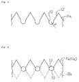
- Fig. 2 is an illustration showing part of the grooves 12.
- Each roller is rotatably supported.
- a cooling medium or heating medium is supplied inside each roller to control the temperature of the resin-impregnated continuous fiber bundle 5.
- the geometry and the position of the grooves 12 in the surface of each roller are such that, when viewed from the running direction of the resin-impregnated continuous fiber bundle 5, the outlines of bottoms 13 of the grooves 12 in the surface of rollers 11a, 11b, and 11c define the shape of the cross section of the target product.
- the target product is intended to have a columnar shape (i.e., the outline of the cross section is a circle with a radius R)
- the bottom 13 of each groove 12 is formed into a semicircle with a radius R.
- each roller The position in the direction of height and axis of each roller is such that, when three rollers 11a, 11b, and 11c are viewed from the running direction of the resin-impregnated continuous fiber bundle 5, one can see circles with a radius R formed by the outlines of the bottoms 13 of grooves 12 as they overlap with each other, as shown in Fig. 4.
- the grooves of rollers 11a, 11b, and 11c need not be completely seen when looked at from the running direction of the resin-impregnated continuous fiber bundle 5.
- the position of the rollers may be displaced so that each resin-impregnated continuous fiber bundle 5 is urged against the bottom of each groove with an adequate force.
- the resin-impregnated continuous fiber bundle 5 transferring between rollers 11a and 11c in Fig. 2 may be urged downward by roll 11b from the upper side to cause the fiber bundle to follow a zigzag course while it runs as it is held by the three rollers.
- the shaping die 6a different from a conventional shaping die 6, has a through hole (having a larger diameter than the shape of the target product) for controlling the amount of the resin melt or performing a small amount of shaping (preliminary shaping).
- This die is useful when shaping is hardly successful because, for example, the shape of the target product is so complicated that use of roller means only cannot provide good shaping.
- the die 6 may be omitted as shown in Fig. 5.
- the imaginary shape formed by the bottoms 13 of grooves 12 of more than two rollers is not necessarily a circle, and various shapes such as ovals are possible depending on the shape of the target product.
- the target product may be a strand, rod, ribbon, tape, sheet, plate, or may take any other special shape. At least two rollers are needed, and three or more rollers may be used to further improve shaping.
- the fiber of the fiber bundle is not particularly limited as to its type in the present invention.
- any high melting point fibers such as glass fibers, carbon fibers, metal fibers, or aromatic polyamide fibers may be used.
- these fibers are generally treated with a surface treatment agent (binder), such treatment is not necessarily required.
- a surface treatment agent binder
- glass fibers are preferable in view of the strength and price of the resulting resin structure reinforced with long fibers.
- a preferable Tex number of the continuous fiber bundle used in the present invention is normally from 4,400 to 120, and more preferably from 2,200 to 740.
- roller bars are used to open the fiber bundle 1.
- Other fiber-opening means may also be used, such as static electricity, blown air (air jet), a water jet, a tension bar, and a needle punch.
- the impregnating means is not particularly limited.
- an impregnation die such as a cross-head die in Fig. 1 or an impregnating vessel may be used, and any impregnation method known in the art may also be used.
- any impregnation method known in the art may also be used.
- use of an impregnation die such as a cross-head die is recommended.
- the resin used for impregnating the fiber bundle is generally a thermoplastic resin, either crystalline or amorphous.
- the thermoplastic resin include polyolefins such as polyethylene and polypropylene; polyesters such as polyethylene terephthalate and polybutylene terephthalate; polyamides such as nylon 6, nylon 66, nylon 11, nylon 12, nylon 610 and nylon 612; polyacetals; polycarbonates, thermoplastic polyurethanes, polyphenylene sulfides, polyphenylene oxides, polysulfones, polyetherketones, polyetheramides, polyetherimides, acrylonitrile/styrene resins, and combinations of these thermoplastic resins.
- Fig. 1 taking manufacture of a pellet-shaped resin structure reinforced with long fibers as an example.
- a fiber bundle 1 taken out of a roving undergoes a fiber opening process between roller bars 2 (fiber-opening step).
- a resin melt supplied from an extruder 3 is impregnated into the fiber with a cross-head die 4 (impregnation step).
- the resulting resin-impregnated continuous fiber bundle 5 is pre-formed with a shaping die 6a for promoting and uniformizing impregnation or for removing excessive amounts of resin, after which the fiber bundle travels as it is guided by the grooves 13 of rollers 11a, 11b, and 11c.
- the fiber bundle is shaped to have a predetermined cross section (for example, a circle with a radius R in Fig. 4) (shaping step).
- the fiber bundle is taken up by take-up rollers 7 (take-up step).
- the take-up rollers 7 employ upper and lower endless belts.
- the taken up resin structure reinforced with long fibers is cut to an arbitrary length with a pelletizer 8.
- the thus-produced pellets are shaped or submitted to other processes.
- a cooling medium or heat medium is passed through the inside of each of rolls 11a to 11c to control the temperature of the resin-impregnated continuous fiber bundle 5 to an optimum level for the take-up step or the subsequent cutting step.
- the obtained pellets contain reinforcing fibers which have substantially the same length as the pellets and which are generally aligned in parallel to the longitudinal direction of the pellets.
- the pellets have a more regular shape than those obtained from the use of a conventional shaping die, and in addition, they contain reduced cracks or separated fibers. This is because, when shaping is effected with rolls as described above, even if the resin melt is unevenly impregnated, the local resin moves to the part in short of resin while the fiber bundle travels through rolls as the upper and lower halves of the fiber bundle are alternatively pressed by the bottoms 13 of the grooves 12, and exposed fibers are embedded in the resin melt.
- the composition, such as the fiber content, of the resin structure reinforced with long fibers obtained as above is not particularly limited. In view of various characteristics of the resulting resin structure, however, it is generally preferred that the fiber content be from 20 to 80% by weight (in the structure), and particularly from 30 to 70% by weight.
- the resin structure reinforced with long fibers according to the present invention may contain optional ingredients which are generally incorporated into resins.
- optional ingredients include anti-oxidants, UV absorbers, antistatics, impregnation facilitating agents, plasticizers, mold releasing agents, fire retardants, fireproofing aids, crystallizing accelerators, colorants, inorganic fillers, and organic fillers.
- a polypropylene-impregnated glass fiber bundle composed of 50% by weight of polypropylene and 50% by weight of glass fibers was taken up at a speed of 4 m/min.
- resin structures reinforced with long fibers with a pellet shape having a length of 12 mm were manufactured.
- Conditions such as the presence or absence of the shaping means of a roller-type and a shaping die, shape of the bottom of grooves of the rollers, shape of the shaping die, etc. were set as shown in Table 1, while other conditions were common throughout the tests.
- the %incidence of generation of cracks in the resulting pellets, amounts of separated glass fibers, etc. are also shown in Table 1.
- shaping of a resin-impregnated continuous fiber bundle is effected with a roller-type shaping means. Therefore, consistent and smooth shaping can be effected without causing cracks in the resulting resin structures or separation of fibers. As a result, resin structures with a good shape, minimized discoloration, and reduced contamination by carbides can be produced with a good yield.
Landscapes
- Chemical & Material Sciences (AREA)
- Engineering & Computer Science (AREA)
- Composite Materials (AREA)
- Mechanical Engineering (AREA)
- Processing And Handling Of Plastics And Other Materials For Molding In General (AREA)
- Reinforced Plastic Materials (AREA)
- Moulding By Coating Moulds (AREA)
Claims (3)
- Vorrichtung zur Herstellung einer mit langen Fasern verstärkten Harzstruktur, umfassend ein Imprägnierungsmittel zum Imprägnieren eines kontinuierlichen Faserbündels mit einer Harzschmelze, während das Faserbündel kontinuierlich gezogen wird, ein Formgebungsmittel, das in einem stromabwärts gelegenen Abschnitt zur Formung des resultierenden, harzimprägnierten, kontinuierlichen Faserbündels vorhanden ist, um einen Querschnitt eines vorgesehenen Endprodukts zu erhalten, und ein Schneidmittel, das in einem noch weiter stromabwärts gelegenen Abschnitt zum Schneiden des harzimprägnierten und geformten, kontinuierlichen Faserbündels vorhanden ist; dadurch gekennzeichnet, daß das Formgebungsmittel eine Mehrzahl von Walzen umfaßt, von denen jede in ihrem äußeren Rand ausgebildete Vertiefungen aufweist, die zur Aufnahme des mit einer Harzschmelze imprägnierten, kontinuierlichen Faserbündels dienen, wobei die Vertiefungen und die Walzen so angeordnet sind, daß die Walzen alternierend in oberen und unteren Positionen mit Bezug auf das gezogene Faserbündel angeordnet sind und die Projektion des Querschnitts der Vertiefungen der Walzen auf die Vertikalebene senkrecht zur Laufrichtung des Faserbündels eine Form des Querschnitts des vorgesehenen Endprodukts bildet.
- Verfahren zur Herstellung einer mit langen Fasern verstärkten Harzstruktur, umfassend einen Imprägnierungsschritt zum Imprägnieren eines kontinuierlichen Faserbündels mit einer Harzschmelze, einen Formgebungsschritt zum Formen des harzimprägnierten, kontinuierlichen Faserbündels, um einen Querschnitt eines vorgesehenen Endprodukts zu erhalten, einen Aufnahmeschritt zum Aufnehmen des harzimprägnierten, kontinuierlichen Faserbündels und einen Schneidschritt zum Schneiden des harzimprägnierten, kontinuierlichen Faserbündels mit einem Schneidmittel zur Herstellung einer mit langen Fasern verstärkten Harzstruktur, dadurch gekennzeichnet, daß der Formgebungsschritt das Übertragen des harzimprägnierten, kontinuierlichen Faserbündels auf eine solche Weise umfaßt, daß es durch Vertiefungen abgestützt wird, die im äußeren Rand von jeder einer Mehrzahl von Walzen ausgebildet sind, wobei die Vertiefungen und die Walzen so angeordnet sind, daß die Walzen alternierend in oberen und unteren Positionen mit Bezug auf das aufgenommene Faserbündel angeordnet sind und die Projektion des Querschnitts der Vertiefungen der Walzen auf die Vertikalebene senkrecht zur Laufrichtung des Faserbündels eine Form des Querschnitts des vorgesehenen Endprodukts bildet.
- Verfahren zur Herstellung einer mit langen Fasern verstärkten Harzstruktur nach Anspruch 2, wobei die Temperatur des kontinuierlichen, mit einer Harzschmelze imprägnierten Faserbündels durch das Leiten eines Kühlmediums oder eines Heizmediums durch die Walzen gesteuert wird.
Applications Claiming Priority (2)
| Application Number | Priority Date | Filing Date | Title |
|---|---|---|---|
| JP24328194A JP3584065B2 (ja) | 1994-09-12 | 1994-09-12 | 長繊維強化樹脂構造物の製造装置及び製造方法 |
| JP243281/94 | 1994-09-12 |
Publications (2)
| Publication Number | Publication Date |
|---|---|
| EP0701893A1 EP0701893A1 (de) | 1996-03-20 |
| EP0701893B1 true EP0701893B1 (de) | 1997-11-19 |
Family
ID=17101529
Family Applications (1)
| Application Number | Title | Priority Date | Filing Date |
|---|---|---|---|
| EP95306331A Expired - Lifetime EP0701893B1 (de) | 1994-09-12 | 1995-09-11 | Vorrichtung und Verfahren zur Herstellung einer mit langen Fasern verstärkten Harzstruktur |
Country Status (4)
| Country | Link |
|---|---|
| US (1) | US5639410A (de) |
| EP (1) | EP0701893B1 (de) |
| JP (1) | JP3584065B2 (de) |
| DE (1) | DE69501071T2 (de) |
Families Citing this family (22)
| Publication number | Priority date | Publication date | Assignee | Title |
|---|---|---|---|---|
| DE19530020A1 (de) * | 1995-08-16 | 1997-02-20 | Menzolit Fibron Gmbh | Verfahren zum Herstellen eines Compounds aus einem Kunststoff mit fester Fasereinlage |
| GB9615995D0 (en) * | 1996-07-30 | 1996-09-11 | Kobe Steel Europ Ltd | Fibre reinforced compositions and methods for their production |
| JP3100567B2 (ja) * | 1997-09-08 | 2000-10-16 | 旭ファイバーグラス株式会社 | 長繊維強化熱可塑性樹脂成形材料 |
| US7056576B2 (en) * | 2001-04-06 | 2006-06-06 | Ebert Composites, Inc. | 3D fiber elements with high moment of inertia characteristics in composite sandwich laminates |
| US6645333B2 (en) | 2001-04-06 | 2003-11-11 | Ebert Composites Corporation | Method of inserting z-axis reinforcing fibers into a composite laminate |
| US6676785B2 (en) | 2001-04-06 | 2004-01-13 | Ebert Composites Corporation | Method of clinching the top and bottom ends of Z-axis fibers into the respective top and bottom surfaces of a composite laminate |
| US7731046B2 (en) * | 2001-04-06 | 2010-06-08 | Ebert Composites Corporation | Composite sandwich panel and method of making same |
| US7105071B2 (en) * | 2001-04-06 | 2006-09-12 | Ebert Composites Corporation | Method of inserting z-axis reinforcing fibers into a composite laminate |
| US20050025948A1 (en) * | 2001-04-06 | 2005-02-03 | Johnson David W. | Composite laminate reinforced with curvilinear 3-D fiber and method of making the same |
| US7785693B2 (en) | 2001-04-06 | 2010-08-31 | Ebert Composites Corporation | Composite laminate structure |
| US20050118448A1 (en) * | 2002-12-05 | 2005-06-02 | Olin Corporation, A Corporation Of The Commonwealth Of Virginia | Laser ablation resistant copper foil |
| US7249943B2 (en) * | 2003-08-01 | 2007-07-31 | Alliant Techsystems Inc. | Apparatus for forming composite stiffeners and reinforcing structures |
| JP4633514B2 (ja) * | 2005-03-30 | 2011-02-16 | オーウェンスコーニング製造株式会社 | 長繊維強化熱可塑性樹脂ロッドの冷却装置 |
| JP4871175B2 (ja) * | 2007-03-12 | 2012-02-08 | 株式会社神戸製鋼所 | 長繊維強化熱可塑性樹脂ペレットの製造方法 |
| US8052823B2 (en) | 2008-01-31 | 2011-11-08 | Alliant Techsystems Inc. | Stiffener tool positioning apparatus |
| US9662841B2 (en) | 2009-11-10 | 2017-05-30 | Orbital Atk, Inc. | Radially extending composite structures |
| US8282757B2 (en) * | 2009-11-10 | 2012-10-09 | Alliant Techsystems Inc. | Automated composite annular structure forming |
| JP5700496B2 (ja) * | 2010-03-08 | 2015-04-15 | 東邦テナックス株式会社 | 炭素繊維チョップドストランド及びその製造法 |
| CN109177239B (zh) * | 2018-09-19 | 2020-10-27 | 东南大学 | 一种曲线型材拉挤生产牵引设备及方法 |
| EP3738740B1 (de) * | 2019-05-13 | 2022-08-10 | Feddem GmbH & Co. KG | Vorrichtung zur querschnittsformung einer vielzahl parallel geführter kunststoff-faserbündel |
| FR3150983A1 (fr) * | 2023-07-13 | 2025-01-17 | Compagnie Generale Des Etablissements Michelin | Installation de fabrication en continu d’un élément composite longiligne de section circulaire |
| FR3150980A1 (fr) * | 2023-07-13 | 2025-01-17 | Compagnie Generale Des Etablissements Michelin | Installation de fabrication en continu d’un élément composite longiligne de section ovale et installation de fabrication d’un ruban comprenant une pluralité d’éléments composites longilignes |
Family Cites Families (22)
| Publication number | Priority date | Publication date | Assignee | Title |
|---|---|---|---|---|
| US2418974A (en) * | 1944-08-24 | 1947-04-15 | Nelson R Henry | Method and apparatus for forming flexible tubes |
| BE759573A (fr) * | 1969-11-28 | 1971-05-27 | Ciba Geigy | Materiaux plastiques renforces |
| US3993726A (en) | 1974-01-16 | 1976-11-23 | Hercules Incorporated | Methods of making continuous length reinforced plastic articles |
| US4194873A (en) * | 1978-01-09 | 1980-03-25 | Ppg Industries, Inc. | Apparatus for making pultruded product |
| AU554594B2 (en) * | 1981-01-21 | 1986-08-28 | Imperial Chemical Industries Plc | Fibre re-inforced |
| US4559262A (en) * | 1981-01-21 | 1985-12-17 | Imperial Chemical Industries, Plc | Fibre reinforced compositions and methods for producing such compositions |
| US5213889B1 (en) * | 1981-01-21 | 1996-10-29 | Kawasaki Chem Holding | Fibre-reinforced compositions and methods for producing such compositions |
| US4549920A (en) * | 1981-07-28 | 1985-10-29 | Imperial Chemical Industries, Plc | Method for impregnating filaments with thermoplastic |
| ATE32227T1 (de) * | 1982-07-28 | 1988-02-15 | Ici Plc | Verfahren zur herstellung von mit faeden verstaerkten zusammensetzungen. |
| JPS6067131A (ja) * | 1983-09-24 | 1985-04-17 | Nippon Valqua Ind Ltd | クラツチフエ−シングの製造方法 |
| US4892600A (en) * | 1988-12-15 | 1990-01-09 | Phillips Petroleum Company | Method and apparatus for pultruding non-linear thermoplastic composite articles |
| US5296064A (en) * | 1989-04-17 | 1994-03-22 | Georgia Tech Research Corp. | Flexible multiply towpreg tape from powder fusion coated towpreg and method for production thereof |
| US5171630A (en) * | 1989-04-17 | 1992-12-15 | Georgia Tech Research Corporation | Flexible multiply towpreg |
| JPH04163002A (ja) * | 1990-10-23 | 1992-06-08 | Toyobo Co Ltd | 複合繊維強化熱可塑性樹脂ペレットの製造方法 |
| KR950013673B1 (ko) * | 1991-01-11 | 1995-11-13 | 미쓰이도오아쓰 가가쿠 가부시키가이샤 | 로드상 섬유 보강 수지재의 연속제조방법 및 그 장치 |
| US5182060A (en) * | 1991-01-31 | 1993-01-26 | E. I. Du Pont De Nemours And Company | Continuous forming of composites |
| JP3210694B2 (ja) * | 1991-09-10 | 2001-09-17 | ポリプラスチックス株式会社 | 繊維強化複合材料の製造方法 |
| IT1254197B (it) * | 1992-02-06 | 1995-09-14 | Donegani Guido Ist | Procedimento per la preparazione di corpi formati in polimeri termoplastici rinforzati con fibra lunga |
| JPH05220852A (ja) * | 1992-02-12 | 1993-08-31 | Ube Nitto Kasei Co Ltd | 長繊維強化ポリアミド樹脂組成物の製造方法 |
| JP2524941B2 (ja) * | 1992-07-09 | 1996-08-14 | 旭ファイバーグラス株式会社 | 連続ガラス繊維強化熱可塑性樹脂ペレット及びその製造法 |
| US5397523A (en) * | 1993-07-20 | 1995-03-14 | Cincinnati Mliacron Inc. | Method and apparatus for sizing composite tows |
| US5395477A (en) * | 1993-10-20 | 1995-03-07 | The United States Of America As Represented By The Administrator Of The National Aeronautics And Space Administration | Apparatus for consolidating a pre-impregnated, filament-reinforced polymeric prepreg material |
-
1994
- 1994-09-12 JP JP24328194A patent/JP3584065B2/ja not_active Expired - Fee Related
-
1995
- 1995-09-11 EP EP95306331A patent/EP0701893B1/de not_active Expired - Lifetime
- 1995-09-11 US US08/526,695 patent/US5639410A/en not_active Expired - Lifetime
- 1995-09-11 DE DE69501071T patent/DE69501071T2/de not_active Expired - Lifetime
Also Published As
| Publication number | Publication date |
|---|---|
| JPH0880577A (ja) | 1996-03-26 |
| EP0701893A1 (de) | 1996-03-20 |
| US5639410A (en) | 1997-06-17 |
| DE69501071D1 (de) | 1998-01-02 |
| DE69501071T2 (de) | 1998-07-02 |
| JP3584065B2 (ja) | 2004-11-04 |
Similar Documents
| Publication | Publication Date | Title |
|---|---|---|
| EP0701893B1 (de) | Vorrichtung und Verfahren zur Herstellung einer mit langen Fasern verstärkten Harzstruktur | |
| EP0707939B1 (de) | Querspritzkopfdüse und Verfahren zum Herstellen eines Strukturkörpers aus Kunststoff verstärkt mit langen Fasern | |
| EP2014433B1 (de) | Vorrichtung und verfahren zur herstellung eines faserverstärkten harzstranges | |
| US5626700A (en) | Method for forming reinforcing structural rebar by pultruding a core and molding thereover | |
| US4615717A (en) | Method and apparatus for making glass fiber oriented continuous strand mat | |
| US20100086727A1 (en) | Method for molding fiber-reinforced thermoplastic composite material, intermediate thereof and composite sheet | |
| US5520867A (en) | Method of manufaturing a resin structure reinforced with long fibers | |
| KR20130088034A (ko) | 연속 섬유 및 장섬유를 함유하는 열가소성 프리프레그 | |
| US5908596A (en) | Process and apparatus for expanding and molding fiberglass laminate and the panel formed thereby | |
| JPS60224530A (ja) | 強化繊維を含有する複合樹脂シ−ト | |
| JPH0732495A (ja) | 長繊維強化熱可塑性樹脂組成物の製造方法 | |
| US5433419A (en) | Method for forming fiber-reinforced molding pellets | |
| CN216914916U (zh) | 一种拉挤制件生产设备及拉挤制件 | |
| CA2075929C (en) | Continuous production process of fiber-reinforced rod-like resin material and apparatus therefor | |
| EP0703065B1 (de) | Verfahren und Vorrichtung zur Herstellung eines langfaserverstärkten Harzgegenstandes | |
| JPH05278126A (ja) | 繊維強化熱可塑性樹脂成形材 | |
| US6132200A (en) | Apparatus and process for texturing a thermoplastic extrusion | |
| JP3415261B2 (ja) | 長繊維強化樹脂構造物の製造方法 | |
| JP2847918B2 (ja) | 押出成形品の製造方法 | |
| CN203004473U (zh) | 对熔融后流动性差的塑料进行复合的装置 | |
| CA1122767A (en) | Thermoforming machines | |
| JP2025141475A (ja) | 繊維強化樹脂シートの製造方法 | |
| JP3667932B2 (ja) | 繊維強化シートの製造方法及び製造装置 | |
| CN119317534A (zh) | 纤丝及造形物的制造方法 | |
| JP2022116765A (ja) | 開繊機構 |
Legal Events
| Date | Code | Title | Description |
|---|---|---|---|
| PUAI | Public reference made under article 153(3) epc to a published international application that has entered the european phase |
Free format text: ORIGINAL CODE: 0009012 |
|
| AK | Designated contracting states |
Kind code of ref document: A1 Designated state(s): DE FR GB |
|
| 17P | Request for examination filed |
Effective date: 19960909 |
|
| GRAG | Despatch of communication of intention to grant |
Free format text: ORIGINAL CODE: EPIDOS AGRA |
|
| 17Q | First examination report despatched |
Effective date: 19970115 |
|
| GRAH | Despatch of communication of intention to grant a patent |
Free format text: ORIGINAL CODE: EPIDOS IGRA |
|
| GRAH | Despatch of communication of intention to grant a patent |
Free format text: ORIGINAL CODE: EPIDOS IGRA |
|
| GRAA | (expected) grant |
Free format text: ORIGINAL CODE: 0009210 |
|
| AK | Designated contracting states |
Kind code of ref document: B1 Designated state(s): DE FR GB |
|
| REF | Corresponds to: |
Ref document number: 69501071 Country of ref document: DE Date of ref document: 19980102 |
|
| ET | Fr: translation filed | ||
| PLBE | No opposition filed within time limit |
Free format text: ORIGINAL CODE: 0009261 |
|
| STAA | Information on the status of an ep patent application or granted ep patent |
Free format text: STATUS: NO OPPOSITION FILED WITHIN TIME LIMIT |
|
| 26N | No opposition filed | ||
| REG | Reference to a national code |
Ref country code: GB Ref legal event code: IF02 |
|
| PGFP | Annual fee paid to national office [announced via postgrant information from national office to epo] |
Ref country code: DE Payment date: 20140903 Year of fee payment: 20 |
|
| PGFP | Annual fee paid to national office [announced via postgrant information from national office to epo] |
Ref country code: GB Payment date: 20140910 Year of fee payment: 20 |
|
| PGFP | Annual fee paid to national office [announced via postgrant information from national office to epo] |
Ref country code: FR Payment date: 20140906 Year of fee payment: 20 |
|
| REG | Reference to a national code |
Ref country code: DE Ref legal event code: R071 Ref document number: 69501071 Country of ref document: DE |
|
| REG | Reference to a national code |
Ref country code: GB Ref legal event code: PE20 Expiry date: 20150910 |
|
| PG25 | Lapsed in a contracting state [announced via postgrant information from national office to epo] |
Ref country code: GB Free format text: LAPSE BECAUSE OF EXPIRATION OF PROTECTION Effective date: 20150910 |