EP0701895B1 - Maschine zum Herstellen von Beuteln - Google Patents
Maschine zum Herstellen von Beuteln Download PDFInfo
- Publication number
- EP0701895B1 EP0701895B1 EP19950250228 EP95250228A EP0701895B1 EP 0701895 B1 EP0701895 B1 EP 0701895B1 EP 19950250228 EP19950250228 EP 19950250228 EP 95250228 A EP95250228 A EP 95250228A EP 0701895 B1 EP0701895 B1 EP 0701895B1
- Authority
- EP
- European Patent Office
- Prior art keywords
- cutter
- point
- notch
- detector
- layers
- Prior art date
- Legal status (The legal status is an assumption and is not a legal conclusion. Google has not performed a legal analysis and makes no representation as to the accuracy of the status listed.)
- Expired - Lifetime
Links
- 239000002985 plastic film Substances 0.000 claims description 61
- 229920006255 plastic film Polymers 0.000 claims description 61
- 239000000463 material Substances 0.000 claims description 53
- 238000011144 upstream manufacturing Methods 0.000 claims description 14
- 239000004033 plastic Substances 0.000 claims description 13
- 230000000149 penetrating effect Effects 0.000 description 5
- 239000000428 dust Substances 0.000 description 2
- 239000011800 void material Substances 0.000 description 2
- 230000007257 malfunction Effects 0.000 description 1
- 238000004080 punching Methods 0.000 description 1
Images

Classifications
-
- B—PERFORMING OPERATIONS; TRANSPORTING
- B31—MAKING ARTICLES OF PAPER, CARDBOARD OR MATERIAL WORKED IN A MANNER ANALOGOUS TO PAPER; WORKING PAPER, CARDBOARD OR MATERIAL WORKED IN A MANNER ANALOGOUS TO PAPER
- B31B—MAKING CONTAINERS OF PAPER, CARDBOARD OR MATERIAL WORKED IN A MANNER ANALOGOUS TO PAPER
- B31B50/00—Making rigid or semi-rigid containers, e.g. boxes or cartons
-
- B—PERFORMING OPERATIONS; TRANSPORTING
- B31—MAKING ARTICLES OF PAPER, CARDBOARD OR MATERIAL WORKED IN A MANNER ANALOGOUS TO PAPER; WORKING PAPER, CARDBOARD OR MATERIAL WORKED IN A MANNER ANALOGOUS TO PAPER
- B31B—MAKING CONTAINERS OF PAPER, CARDBOARD OR MATERIAL WORKED IN A MANNER ANALOGOUS TO PAPER
- B31B70/00—Making flexible containers, e.g. envelopes or bags
- B31B70/006—Controlling; Regulating; Measuring; Safety measures
-
- B—PERFORMING OPERATIONS; TRANSPORTING
- B31—MAKING ARTICLES OF PAPER, CARDBOARD OR MATERIAL WORKED IN A MANNER ANALOGOUS TO PAPER; WORKING PAPER, CARDBOARD OR MATERIAL WORKED IN A MANNER ANALOGOUS TO PAPER
- B31B—MAKING CONTAINERS OF PAPER, CARDBOARD OR MATERIAL WORKED IN A MANNER ANALOGOUS TO PAPER
- B31B50/00—Making rigid or semi-rigid containers, e.g. boxes or cartons
- B31B50/14—Cutting, e.g. perforating, punching, slitting or trimming
- B31B50/16—Cutting webs
-
- G—PHYSICS
- G05—CONTROLLING; REGULATING
- G05B—CONTROL OR REGULATING SYSTEMS IN GENERAL; FUNCTIONAL ELEMENTS OF SUCH SYSTEMS; MONITORING OR TESTING ARRANGEMENTS FOR SUCH SYSTEMS OR ELEMENTS
- G05B2219/00—Program-control systems
- G05B2219/30—Nc systems
- G05B2219/41—Servomotor, servo controller till figures
- G05B2219/41177—Repetitive control, adaptive, previous error during actual positioning
-
- G—PHYSICS
- G05—CONTROLLING; REGULATING
- G05B—CONTROL OR REGULATING SYSTEMS IN GENERAL; FUNCTIONAL ELEMENTS OF SUCH SYSTEMS; MONITORING OR TESTING ARRANGEMENTS FOR SUCH SYSTEMS OR ELEMENTS
- G05B2219/00—Program-control systems
- G05B2219/30—Nc systems
- G05B2219/45—Nc applications
- G05B2219/45153—Carton forming
-
- Y—GENERAL TAGGING OF NEW TECHNOLOGICAL DEVELOPMENTS; GENERAL TAGGING OF CROSS-SECTIONAL TECHNOLOGIES SPANNING OVER SEVERAL SECTIONS OF THE IPC; TECHNICAL SUBJECTS COVERED BY FORMER USPC CROSS-REFERENCE ART COLLECTIONS [XRACs] AND DIGESTS
- Y10—TECHNICAL SUBJECTS COVERED BY FORMER USPC
- Y10T—TECHNICAL SUBJECTS COVERED BY FORMER US CLASSIFICATION
- Y10T83/00—Cutting
- Y10T83/04—Processes
- Y10T83/0495—Making and using a registration cut
-
- Y—GENERAL TAGGING OF NEW TECHNOLOGICAL DEVELOPMENTS; GENERAL TAGGING OF CROSS-SECTIONAL TECHNOLOGIES SPANNING OVER SEVERAL SECTIONS OF THE IPC; TECHNICAL SUBJECTS COVERED BY FORMER USPC CROSS-REFERENCE ART COLLECTIONS [XRACs] AND DIGESTS
- Y10—TECHNICAL SUBJECTS COVERED BY FORMER USPC
- Y10T—TECHNICAL SUBJECTS COVERED BY FORMER US CLASSIFICATION
- Y10T83/00—Cutting
- Y10T83/525—Operation controlled by detector means responsive to work
- Y10T83/533—With photo-electric work-sensing means
-
- Y—GENERAL TAGGING OF NEW TECHNOLOGICAL DEVELOPMENTS; GENERAL TAGGING OF CROSS-SECTIONAL TECHNOLOGIES SPANNING OVER SEVERAL SECTIONS OF THE IPC; TECHNICAL SUBJECTS COVERED BY FORMER USPC CROSS-REFERENCE ART COLLECTIONS [XRACs] AND DIGESTS
- Y10—TECHNICAL SUBJECTS COVERED BY FORMER USPC
- Y10T—TECHNICAL SUBJECTS COVERED BY FORMER US CLASSIFICATION
- Y10T83/00—Cutting
- Y10T83/525—Operation controlled by detector means responsive to work
- Y10T83/541—Actuation of tool controlled in response to work-sensing means
- Y10T83/543—Sensing means responsive to work indicium or irregularity
Definitions
- the invention relates to a bag making machine for successively make plastic bags.
- a bag making machine which includes feeding means such as feeding rollers rotated by a servo motor for feeding two or more superposed layers of plastic film 1 longitudinally thereof and intermittently for a length, as shown in Fig. 14.
- feeding means such as feeding rollers rotated by a servo motor for feeding two or more superposed layers of plastic film 1 longitudinally thereof and intermittently for a length, as shown in Fig. 14.
- Longitudinal and cross sealers are operated to heat seal the layers of plastic film 1 longitudinally and crossly thereof whenever feeding of the layers of plastic film 1 are temporarily stopped so that longitudinal and cross sealed areas 2 and 3 are formed on the layers of plastic film 1.
- the longitudinal sealed areas 2 extend parallel to the feeding direction X of the layers of plastic film 1.
- the cross sealed areas 3 extend perpendicularly to the feeding direction X.
- Notch holes 4 may then be punched in the intersection between the longitudinal and cross sealed areas 2 and 3 of the layers whenever the layers of plastic film 1 are temporarily stopped.
- a slitter slits the layers of plastic film 1 along longitudinal lines Y0 extending through the centers of the notch holes 4.
- a cutter is operated to cut the layers of plastic film 1 crossly thereof along a cross line X0 extending through the centers of the notch holes 4 whenever the layers of plastic film 1 are temporarily stopped, the thereby successively make plastic bags.
- Each of the plastic bags has four bevelled or round corners formed by the notch holes 4.
- a cutting apparatus for precisely cutting is disclosed in Japanese Laid-Open Patent Publication No. 160231 of 1987, the applicant of which is Totani.
- a light source and a detector are disposed near the cutter on the upper side of the layers feeding path. The light source directs a light toward the layers of plastic film around the notch hole when the layers of plastic film are temporarily stopped. The light passes through the notch hole, a portion of the light reflecting from the layers of plastic film around the notch hole.
- the detector includes a series of elements arranged along a line extending crossly of the layers of plastic film the elements receive the light reflecting from the layers of plastic film to thereby measure the width of the notch hole on the line along which the elements are arranged.
- the apparatus compares the measured value of the width of the notch hole on the line with a reference value which corresponds to the width of the notch hole at the center thereof, to thereby calculate the difference between the position of the cross line extending through the centers of the notch holes and the position of the cutting edge of the cutter.
- Drive means moves the cutter parallel to the layers feeding direction to thereby compensate and eliminate the difference between the position of the cross line extending through the centers of the notch holes and the position of the cutting edge of the cutter.
- the cutter then cut the layers of plastic film crossly thereof.
- the layers of plastic film can therefore be cut precisely along the cross line extending through the centers of notch holes.
- the protrusions 5 are not formed at the corners of plastic bags.
- the apparatus has a problem that the layers of plastic film 1 may spread out after slitting the layers along the longitudinal line Y0 to widen the notch hole 4. This affects the measured value of the width of the notch hole 4, resulting in miscalculation of the difference between the position of the cross line X0 extending through the center of the notch holes 4 and the position of the cutting edge of the cutter. A dust may be adhered to the periphery of the notch hole 4. This also affects the measured value.
- the notch holes 4 may be rugged by the malfunction of the punching means to affect the measured value. Accordingly, the apparatus can not always cut the layers of plastic film 1 precisely along the cross line X0 extending through the center of notch holes 4.
- JP-A-03227228 discloses a bag making machine which includes a cutter with cutting edge means for cutting a plastic film material along a predetermined line.
- a light source is disposed upstream of the cutter on a first side of a material feeding path.
- a detector is opposed to the light source on a second side opposite from the first side of the material feeding path for receiving light passing through a through-hole, where by the quantity of that light is detected.
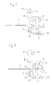
- Fig. 1 is a side view of a preferred embodiment of the invention.
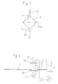
- Fig. 2 is a schematic plan view showing the recognizing range of the detector in Fig. 1.
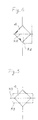
- Fig. 3 is a schematic plan view showing other recognizing range of the detector in Fig. 1.
- Fig. 4 is a schematic plan view showing other recognizing range of the detector in Fig. 1.
- Fig. 5 is a schematic plan view showing other recognizing range of the detector in Fig. 1.
- Fig. 6 is a side view of other embodiment of the invention.
- Fig. 7 is a side view of other embodiment of the invention.
- Fig. 8 is a side view showing the position of the notch hole when the layers of plastic film are temporarily stopped in Fig. 7.
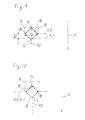
- Fig. 9 is a schematic plan view showing the recognizing range of the detector in Fig. 7.
- Fig. 10 is a schematic plan view showing the recognizing range of the detector in Fig. 8.
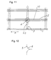
- Fig. 11 is a schematic plan view showing notch holes formed in the intersection between the longitudinal and cross sealed areas of the layers of plastic films.
- Fig. 12 is a schematic plan view showing protrusions formed at the corners of plastic bags.
- a bag making machine which includes feeding means such as feed rollers rotated by a servo motor for feeding two superposed layers of plastic film 1 longitudinally thereof and intermittently for a length, as described above.
- the bag making machine further includes longitudinal and cross sealers operated by a servo motor to heat seal the layers of plastic film 1 longitudinaly and crossly thereof whenever feeding of the layers of plastic film 1 are temporarily stopped so that longitudinal and cross sealed areas 2 and 3 are formed on the layers of plastic film 1.
- the longitudinal sealed areas 2 extend parallel to the feeding direction X of the layers of plastic film 1.
- the cross sealed areas 3 extend perpendicularly to the feeding direction X.
- Notch holes 4 are then punched in the intersection between the longitudinal and cross sealed areas 2 and 3 of the layers whenever the layers of plastic film 1 are temporarily stopped.
- a slitter slits the layers of plastic film 1 along longitudinal lines Y0 extending through the centers of the notch holes 4.
- the notch hole 4 is rectangular having an upstream end A, two central ends B and a downstream end C, the slitting line Y0 extending through the upstream and downstream ends A and C of the notch hole 4, shown in Fig. 2.
- the layers of plastic film 1 have void area means comprising the notch holes 4.
- the bag making machine further includes a cutter 6 operated by the servo motor common to the sealers and the cutter 6 to cut the layers of plastic film 1 crossly thereof along a line predetermined with respect to the void area means whenever the layers of plastic film 1 are temporarily stopped, to thereby successiveively make plastic bags.
- the predetermined line comprises a cross line X0 extending through the centers or central ends B of the notch holes 4.
- Each of the plastic bags has four bevelled or round corners formed by the notch holes 4.
- a light source 7 is disposed near and upstream of the cutter 6 on one side of the layers feeding path.
- a detector 8 is opposed to the light source 7 on the other side of the layers feeding path.
- the layers of plastic film 1 are fed along a path extending horizontally, the light source 7 being positioned on the lower side of the layers feedig path, the detector 8 being positioned on the upper side of the layers feeding path.
- the detector 8 comprises a video camera including an electronic shutter.
- the light source 7 is intended to direct a light toward the layers of plastic film 1 and the cutter 6 when the layers of plastic film 1 are fed at a low speed and the notch hole 4 reaches the position of the light source 7, as shown in Fig. 1, immediately before the layers of plastic film 1 are temporarily stopped.
- the detector 8 is adapted to receive the light passing through the notch hole 4, the cutter 6 intercepting a portion of the light passing through the notch hole 4.
- the electronic shutter is clicked instaneously so that the detector 8 recognizes the contour of the notch hole 4 as an image data in a range R at least between the predetermined line X0 of the layers and a portion of the cutter 6, as shown in Fig. 2, immediately before the layers of plastic film 1 are temporarily stopped.
- the layers of plastic film 1 are further fed a length L (about 8 mm) and then temporarily stopped by the feeding rollers driven by the servo motor.
- the bag making machine further includes a computer 9 connected to the detector 8.
- the computer 9 calculates the distance D1 between the position of the predetermined line X0 of the layers and the position of the side X2 of the cutter 6 at the image data recognizing point in accordance with the image data of the detector 8.
- the computer 9 add that distance D1 to the distance D2 between the position of the side X2 of the cutter 6 and the position of the cutting edge X1 thereof, the distance D2 being previously recognized by the computer 9, to thereby calculate the distance D1 + D2 between the position of the predetermined line X0 of the layers and the position of the cutting edge X1 of the cutter 6 at the image data recognizing point.
- the computer 9 measures or computes the feed length L of the layers of plastic film 1 from the image data recognizing point to the layers temporarily stopping point.
- the computer 9 counts the number of pulses which are sent from the servo motor driving the feeding rollers to the computer 9 after the image data recognizing point, to measure the feed length L.
- the computer 9 compares the distance D1 + D2 at the image data recognizing point with the feed length L from the image data recognizing point to the layers temporarily stopping point, to thereby calculate the difference L - (D1 + D2) between the position of the predetermined line X0 of the layers and the position of the cutting edge X1 of the cutter 6 at the layers temporarily stopping point.
- the bag making machine further includes drive means connected to the computer 9 for moving the cutter 6 parallel to the layers feeding direction X.
- the drive means comprises a servo motor 10 connected to the computer 9, a feeding screw 11 extending parallel to the layers feeding direction X and operatively connected to the servo motor 10, and a nut member 12 threadedly engaged with the feeding screw 11 and mounted on a frame 13, the cutter 6 being supported on the frame 13.
- the servo motor 10 rotates the feeding screw 11 in response to the output signal from the computer 9, after calculating the difference L - (D1 + D2).
- the feeding screw 11 and the nut member 12 therefore move the cutter 6 and frame 13 parallel to the layers feeding direction X in response to the output signal from the computer 9, to thereby compensate and eliminate the difference L - (D1 + D2) between the position of the predetermined line X0 of the layers and the position of the cutting edge X1 of the cutter 6 at the layers temporarily stopping point.
- the cutter 6 is then operated by the servo motor common to the sealers and the cutter 6 to cut the layers of plastic film 1 crossly thereof.
- the layers of plastic film 1 can therefore be cut precisely along the cross line X0 extending through the centers of the notch holes 4.
- the protrusions 5 shown in Fig. 19 are not formed at the corners of plastic bags.
- the layers of plastic film may spread out after slitting along the longitudinal line Y0 to widen the notch hole 4, as shown in Fig. 3.
- the computer 9 compares the image data of the detector 8 with the previous image data to judge the unusualness in the image data so that the detector 8 recognizes only an usual image data in a range R1 and cancell the other image data.
- the computer 9 calculates the difference between the position of the predetermined line X0 of the layers and the position of the cutting edge X1 of the cutter 6 in accordance with the image data in the range R1. If the dust is adhered to the periphery of the notch hole 4, the detector 8 recognizes only an usual image data in a range R2 and cancell the other image data, as shown in Fig. 4.
- the bag making machine can compensate and eliminate the difference between the position of the predetermined line X0 of the layers and the position of the cutting edge X1 of the cutter 6 without miscalculation, to thereby cut the layers of plastic film 1 precisely along the predetermined line thereof.
- a bag making machine for feeding transparent layers of plastic film 1.
- the bag making machine includes two polarizing screens 14 and 15 disposed the opposite sides of the layers feeding path.
- the light source 7 is covered by the polarizing screen 14.
- the detector 8 is covered by the polarizing screen 15.
- the light source 7 therefore directs a light to the polarizing screen 14, the light penetrating through the polarizing screen 14 by which the light is polarized.
- the light then passes through the notch hole 4 and penetrates through the layers of plastic film 1 around the notch hole 4 to reach the polarizing screen 15 by which the light is again polarized.
- the polarizing screens 14 and 15 have orientations perpendicular to each other.
- the layers of plastic film 1 rotate the wave front of the light polarized by the polarizing screen 14 so that the light can penetrate through the polarizing screen 15.
- the detector 8 therefore receives not the light passing through the notch hole 4 but the light penetrating through the layers of plastic film 1 around the notch hole 4, to recognize the contour of the notch hole 4 as an image data. Accordingly, even if the transparent layers of plastic film 1, the computer 9 can calculate the difference L - (D1 + D2) , between the position of the predetermined line X0 of the layers and the position of the cutting edge X1 of the cutter 6, as described above.
- the light source 7 direct a light toward the layers of plastic film 1 so that the detector 8 receives the light passing through the notch hole 4, or the light penetrating through the layers of plastic film 1 around the notch hole 4, immediately before the layers of plastic film 1 are temporarily stopped.
- the detector 8 recognizes the contour of the notch hole 4 as an image data in a range R at least between the predetermined line X0 of the layers and a reference portion of the layers, the reference portion comprising the upstream end A of the notch hole 4, which is positioned upstream of the predetermined line X0, as shown in Fig. 9.
- the computer 9 calculates the distance between the predetermined line X0 of the layers and the upstream end A of the notch hole 4 in accordance with the image data of the detector 8 immediately before the layers of plastic film 1 are temporarily stopped.
- the light source 7 then again directs a light toward the layers of plastic film 1 so that the detector 8 receives the light passing through the notch hole 4, or the light penetrating through the layers of plastic film 1 around the notch hole 4, when the layers of plastic film 1 are temporarily stopped, as shown in Fig. 8.
- the detector 8 recognizes the contour of the notch hole 4 as an image data in a range R including the reference portion of the layers, that is the upstream end A of the notch hole 4, as shown in Fig. 10.
- the computer 9 calculates the distance between the position of the upstream end A of the notch hole 4 and the position of the cutting edge X1 of the cutter 6 in accordance with the image data of the detector 8 when the layers of plastic film 1 are temporarily stopped.
- the computer 9 compares the distance between the predetermined line X0 of the layers and the upstream end A of the notch hole 4 with the distance between the position of the upstream end A of the notch hole 4 and the position of the cutting edge X1 of the cutter 6, to thereby calculate the difference between the position of the predetermined line X0 of the layers and the position of the cutting edge X1 of the cutter 6.
- the servo motor 10 rotates the feeding screw 11 and moves the cutter 6 and the frame 13 parallel to the layers feeding direction X in response to the output signal from the computer 9, to thereby compensate and eliminate the difference between the position of the predetermined line X0 of the layers and the position of the cutting edge X1 of the cutter 6. Accordingly, the layers of plastic film 1 can be cut precisely along the cross line X0 extending through the centers of the notch holes 4.
Landscapes
- Making Paper Articles (AREA)
- Controlling Rewinding, Feeding, Winding, Or Abnormalities Of Webs (AREA)
Claims (2)
- Maschine zur Herstellung von Kunststoffbeuteln aus einem Bahnmaterial mit zwei oder mehr Schichten einer Kunststofffolie (1), das in ihm ausgebildete Ausklinkmittel, wie Ausklinklöcher (4) aufweist, wobei die Maschine zur Herstellung von Beuteln umfasst,
Zuführmittel zum intermittierenden Zuführen des Materials (1) um eine Länge längs einer longitudinalen Materialzufuhrstrecke, eine Schneidvorrichtung mit einem Schneidkantenmittel zum Schneiden des Materials (1) entlang einer vorbestimmten Linie, die sich in einer Richtung quer zu der longitudinalen Materialzufuhrrichtung (X) erstreckt und die Ausklinkmittel (4) schneidet, immer wenn die Zufuhr des Materials (1) zeitweise gestoppt wird, um dabei aufeinanderfolgend Kunststoffbeutel herzustellen, eine Lichtquelle (7), die stromaufwärts zu der Schneidvorrichtung (6) auf einer ersten Seite der Materialzufuhrstrecke angeordnet ist, um Licht auf das Material (1) zu richten und einen Detektor (8), der der Lichtquelle (7) auf einer zweiten Seite entgegensetzt zu der ersten Seite der Materialzufuhrstrecke gegenüberliegt, um das durch die Ausklinkmittel (4) hindurchgehende Licht zu empfangen, wobei die Maschine zur Herstellung von Beuteln
dadurch gekennzeichnet ist, daßdie Lichtquelle (7) nahe der Schneidvorrichtung (6) auf der ersten Seite angeordnet ist, um das Licht zu dem Material (1) und der Schneidvorrichtung (6) zu richten, daßder Detektor (8) gegenüberliegend zu der Lichtquelle (7) auf der zweiten Seite zum Empfangen des durch die Ausklinkmittel (4) hindurchgehenden Lichts an einem ersten Punkt, unmittelbar bevor das Material (1) zeitweise gestoppt wird, angeordnet ist, wobei der Detektor (8) das durch die Ausklinkmittel (4) hindurchgehende Licht als Bilddaten erkennt, die der Kontur der Ausklinkmittel (4) entsprechen, um die Position der vorbestimmten Linie (X0) des Materials (1) und die Position der Schneidkantenmittel (X1) der Schneidvorrichtung (6) in der Materialzufuhrrichtung (X) an dem ersten Punkt zu detektieren, wobei das Material (1) dann zeitweise an einem zweiten Punkt gestoppt wird, nachdem die Zufuhrmittel das Material (1) weiter um ein verbleibendes Längensegment (L), vorgeschoben von dem ersten Punkt zum zweiten Punkt, zuführen,daß ein Computer (9) mit dem Detektor (8) verbunden ist zum Berechnen eines Abstandes (D1 + D2) zwischen der Position der vorbestimmten Linie (X0) des Materials (1) und der Position des Schneidkantenmittels (X1) der Schneidvorrichtung (6) in der Materialzufuhrrichtung (X) an dem ersten Punkt in Übereinstimmung mit von dem Detektor (8) empfangenen detektierten Daten, um das verbleibende Längensegment (L) zu messen oder zu berechnen und den Abstand (D1 + D2) mit dem verbleibenden Längensegment (L) zu vergleichen, wobei eine Differenz (L-(D1 + D2)) zwischen der Position der vorbestimmten Linie des Materials (1) und der Position des Schneidkantenmittels (X1) der Schneidvorrichtung (6) in der Materialzufuhrrichtung (X) an dem zweiten Punkt berechnet wird, wobei der Computer (9) aufeinander folgend ein Ausgangssignal erzeugt, das sich auf die Differenz (L-(Dl + D2)) bezieht und daß Schneidvorrichtungs-Antriebsmittel (10) mit dem Computer (9) zum Bewegen der Schneidvorrichtung (6) parallel zu der Materialzufuhrrichtung (X) abhängig von dem Ausgangssignal von dem Computer (9) verbunden sind, um dabei die Position des Schneidkantenmittels (X1) der Schneidvorrichtung (6) in der Materialzufuhrrichtung (X) einzustellen und die Differenz (L-(D1 + D2) zu kompensieren und eliminieren derart, daß das Material (1) genau längs der vorbestimmten Linie durch das Schneidkantenmittel der Schneidvorrichtung (6) geschnitten werden kann. - Maschine zur Herstellung von Kunststoffbeuteln aus einem Bahnmaterial mit zwei oder mehr Schichten einer Kunststofffolie (1), das in ihm ausgebildete Ausklinkmittel, wie Ausklinklöcher (4) aufweist, wobei die Maschine zur Herstellung von Beuteln umfasst,Zuführmittel zum intermittierenden Zuführen des Materials (1) um eine Länge längs einer longitudinalen Materialzufuhrstrecke, eine Schneidvorrichtung (6) mit einem Schneidkantenmittel zum Schneiden des Materials (1) entlang einer vorbestimmten Linie, die sich in einer Richtung quer zu der longitudinalen Materialzufuhrrichtung (X) erstreckt und die Ausklinkmittel (4) schneidet, immer wenn die Zufuhr des Materials (1) zeitweise gestoppt wird, um dabei aufeinander folgend Kunststoffbeutel herzustellen, eine Lichtquelle (7), die stromaufwärts zu der Schneidvorrichtung (6) auf einer ersten Seite der Materialzufuhrstrecke angeordnet ist, um Licht auf das Material (1) zu richten und einen Detektor (8), der der Lichtquelle (7) auf einer zweiten Seite entgegengesetzt zu der ersten Seite der Materialzufuhrstrecke gegenüberliegt, um das durch die Ausklinkmittel (4) hindurchgehende Licht zu empfangen, wobei die Maschine zur Herstellung von Beuteln dadurch gekennzeichnet ist, daß die Lichtquelle (7) nahe der Schneidvorrichtung (6) auf der ersten Seite angeordnet ist, daßder Detektor (8) gegenüberliegend zu der Lichtquelle (7) auf der zweiten Seite zum Empfangen des durch die Ausklinkmittel (4) hindurchgehenden Lichts an einem Punkt, unmittelbar bevor das Material (1) zeitweise gestoppt wird, angeordnet ist und das durch die Ausklinkmittel (4) hindurchgehende Licht als Bilddaten erkennt, die der Kontur der Ausklinkmittel (4) entsprechen, um die Position der vorbestimmten Linie (X0) des Materials (1) und die Position eines Referenzteils (A) des Materials (1), das stromaufwärts zu der vorbestimmten Linie in der Materialzufuhrrichtung (X) angeordnet ist, an dem ersten Punkt zu detektieren, wobei das Material (1) dann zeitweise an einem zweiten Punkt gestoppt wird, nachdem die Zufuhrmittel das Material (1) weiter um ein verbleibendes Längensegment (L), vorgeschoben von dem ersten Punkt zum zweiten Punkt, zuführen, wobei der Detektor (8) weiterhin das durch die Ausklinkmittel (4) an dem zweiten Punkt hindurchgehende Licht empfängt und das durch die Ausklinkmittel (4) hindurchgehende Licht als Bilddaten erkennt, die der Kontur der Ausklinkmittel (4) entsprechen, um die Position des Referenzteils (A) des Materials (1) in der Materialzufuhrrichtung (X) an dem zweiten Punkt zu detektieren, daßein Computer (9) mit dem Detektor verbunden ist zum Berechnen eines Abstandes zwischen der Position der vorbestimmten Linie (X0) des Materials (1) und der Position des Referenzteils (A) des Materials (1) in der Materialzufuhrrichtung (X) an dem ersten Punkt in Übereinstimmung mit von dem Detektor (8) empfangenen detektierten Daten, zum Berechnen eines zweiten Abstandes zwischen der Position des Referenzteils (A) des Materials (1) und der Position des Schneidkantenmittels (X1) der Schneidvorrichtung (6) in der Materialzufuhrrichtung (X) an dem zweiten Punkt in Übereinstimmung mit empfangenen, von dem Detektor (8) detektierten Daten und zum Vergleich des ersten Abstandes mit dem zweiten Abstand, um dabei eine Differenz zwischen der Position der vorbestimmten Linie (X0) des Materials (1) und der Position des Schneidkantenmittels (X1) der Schneidvorrichtung (6) an dem zweiten Punkt zu berechnen, wobei der Computer (9) aufeinander folgend ein Ausgangssignal erzeugt, das sich auf die Differenz bezieht und daßSchneidvorrichtungs-Antriebsmittel (10) mit dem Computer (9) zum Bewegen der Schneidvorrichtung (6) parallel zu der Materialzufuhrrichtung (X) abhängig von dem Ausgangssignal des Computers (9) verbunden sind, um dabei die Position des Schneidkantenmittels (X1) der Schneidvorrichtung (6) in der Materialzufuhrrichtung (X) einzustellen und die Differenz zu kompensieren und eliminieren, derart, daß das Material (1) genau längs der vorbestimmten Linie durch das Schneidkantenmittel der Schneidvorrichtung (6) geschnitten werden kann.
Applications Claiming Priority (6)
| Application Number | Priority Date | Filing Date | Title |
|---|---|---|---|
| JP12772/94 | 1994-09-19 | ||
| JP1277294 | 1994-09-19 | ||
| JP1994012772U JP3009204U (ja) | 1994-09-19 | 1994-09-19 | 製袋機の袋切断装置 |
| JP26074895 | 1995-09-12 | ||
| JP26074895A JP3620899B2 (ja) | 1995-09-12 | 1995-09-12 | 製袋機の袋切断装置 |
| JP260748/95 | 1995-09-12 |
Publications (3)
| Publication Number | Publication Date |
|---|---|
| EP0701895A2 EP0701895A2 (de) | 1996-03-20 |
| EP0701895A3 EP0701895A3 (de) | 1996-12-11 |
| EP0701895B1 true EP0701895B1 (de) | 2000-02-09 |
Family
ID=26348433
Family Applications (1)
| Application Number | Title | Priority Date | Filing Date |
|---|---|---|---|
| EP19950250228 Expired - Lifetime EP0701895B1 (de) | 1994-09-19 | 1995-09-18 | Maschine zum Herstellen von Beuteln |
Country Status (4)
| Country | Link |
|---|---|
| US (1) | US5807222A (de) |
| EP (1) | EP0701895B1 (de) |
| DE (1) | DE69514972T2 (de) |
| ES (1) | ES2141889T3 (de) |
Families Citing this family (17)
| Publication number | Priority date | Publication date | Assignee | Title |
|---|---|---|---|---|
| DE69820503T2 (de) * | 1997-01-30 | 2004-11-04 | Totani Giken Kogyo Co. Ltd. | Blattzuführvorrichtung |
| DE19751798A1 (de) * | 1997-11-24 | 1999-05-27 | Lemo Maschb Gmbh | Verfahren und Vorrichtung zum gleichzeitigen Herstellen von jeweils zwei Beuteln, insbesondere Automatenbeuteln aus Doppelfolienbahnabschnitten einer flachgelegten Schlauchbahn |
| DE19825080B4 (de) * | 1998-06-04 | 2004-03-11 | Indag Gesellschaft für Industriebedarf mbH & Co. Betriebs KG | Verfahren und Vorrichtung zur Herstellung von Folienbeuteln |
| EP1146312B1 (de) * | 1999-10-25 | 2006-12-13 | Totani Giken Kogyo Co., Ltd. | Wärmeverschluss-positionsapparat für plastikschichten |
| DE10147617B4 (de) * | 2001-09-27 | 2016-05-25 | Weber Maschinenbau Gmbh & Co. Kg | Aufschneidevorrichtung |
| SE520285C2 (sv) * | 2001-10-29 | 2003-06-17 | Straalfors Ab | Förfarande och anordning vid löpande banor som försetts med tryck i en höghastighetsprinter |
| DE20120977U1 (de) * | 2001-12-27 | 2003-04-30 | British American Tobacco (Germany) GmbH, 20354 Hamburg | Schnittkontrolle für eine Innenumhüllung für eine Zigarettengruppe |
| EP1772405B1 (de) * | 2005-10-05 | 2009-04-08 | Bobst S.A. | Verfahren zum Positionieren von plattenförmigen Gegenständen in einer Verarbeitungsmaschine |
| US20100255973A1 (en) * | 2007-05-15 | 2010-10-07 | Desmedt Eric | Method of making and inspecting bags |
| US20100249997A1 (en) | 2009-03-25 | 2010-09-30 | Greyshock Shawn T | System, method and corresponding apparatus for detecting perforations on a unit dose blister card |
| ES2566949T3 (es) * | 2009-03-26 | 2016-04-18 | Roll-O-Matic A/S | Un proceso de fabricación de bolsas |
| US8869667B2 (en) | 2009-12-04 | 2014-10-28 | Aesynt Incorporated | System, method and corresponding apparatus for singulating a unit dose blister card |
| US8640586B2 (en) | 2010-03-23 | 2014-02-04 | Mckesson Automation Inc. | Method and apparatus for facilitating cutting of a unit dose blister card |
| US8453548B2 (en) * | 2010-03-23 | 2013-06-04 | Mckesson Automation Inc. | Apparatuses for cutting a unit dose blister card |
| EP2422973B1 (de) * | 2010-08-31 | 2013-06-05 | Heidelberger Druckmaschinen Aktiengesellschaft | Inspektionsmodul |
| EP2704112A1 (de) * | 2012-08-31 | 2014-03-05 | Evondos Oy | Verfahren zum Betrieb eines Medikamentenausgabe und Medikamentenausgabe |
| ES2460467B1 (es) * | 2012-11-09 | 2015-06-30 | Mespack, Sl | Máquina horizontal formadora y llenadora de envases flexibles, y método de control de un dispositivo de corte de dicha máquina |
Family Cites Families (13)
| Publication number | Priority date | Publication date | Assignee | Title |
|---|---|---|---|---|
| US4220077A (en) * | 1978-03-22 | 1980-09-02 | Owens-Illinois, Inc. | Composite can registration |
| US4205769A (en) * | 1978-05-05 | 1980-06-03 | Western Electric Company, Inc. | Methods of and system for counting holes and for detecting missing holes in a web |
| JPS59123647A (ja) * | 1982-12-29 | 1984-07-17 | Bridgestone Corp | コ−テイングシ−トの端部切断装置 |
| DE3544251A1 (de) * | 1985-12-14 | 1987-06-19 | Duerkopp System Technik Gmbh | Verfahren und vorrichtung zum selbsttaetigen zuschneiden von teilen aus flaechigem naehgut nach mit unterschiedlichen konturen versehenen mustervorlagen auf einer koordinaten-schneidmaschine |
| JPH069880B2 (ja) * | 1986-01-08 | 1994-02-09 | トタニ技研工業株式会社 | 製袋機の袋切断装置 |
| US4790694A (en) * | 1986-10-09 | 1988-12-13 | Loma Park Associates | Method and system for multi-layer printed circuit board pre-drill processing |
| AT393986B (de) * | 1989-06-26 | 1992-01-10 | Payr Hans | Vorrichtung zum zerteilen von werkstuecken, insbesondere von holz |
| JP2805515B2 (ja) * | 1989-12-27 | 1998-09-30 | トタニ技研工業株式会社 | プラスチック袋製造装置 |
| JP2853231B2 (ja) * | 1990-02-01 | 1999-02-03 | 藤森工業株式会社 | 包装方法 |
| GB9006804D0 (en) * | 1990-03-27 | 1990-05-23 | Thurne Eng Co Ltd | Slicing machine |
| GB9006803D0 (en) * | 1990-03-27 | 1990-05-23 | Thurne Eng Co Ltd | Boundary recognition |
| CH682600A5 (fr) * | 1990-04-18 | 1993-10-15 | Bobst Sa | Procédé de contrôle de qualité de l'impression et du découpage dans une installation de production d'emballages. |
| US5212656A (en) * | 1991-04-26 | 1993-05-18 | Prime Technology, Inc. | Box inspection device and method |
-
1995
- 1995-09-18 EP EP19950250228 patent/EP0701895B1/de not_active Expired - Lifetime
- 1995-09-18 DE DE69514972T patent/DE69514972T2/de not_active Expired - Lifetime
- 1995-09-18 ES ES95250228T patent/ES2141889T3/es not_active Expired - Lifetime
- 1995-09-19 US US08/530,416 patent/US5807222A/en not_active Expired - Lifetime
Also Published As
| Publication number | Publication date |
|---|---|
| DE69514972T2 (de) | 2000-07-20 |
| EP0701895A2 (de) | 1996-03-20 |
| EP0701895A3 (de) | 1996-12-11 |
| US5807222A (en) | 1998-09-15 |
| DE69514972D1 (de) | 2000-03-16 |
| ES2141889T3 (es) | 2000-04-01 |
Similar Documents
| Publication | Publication Date | Title |
|---|---|---|
| US5807222A (en) | Bag making machine | |
| EP0485691B1 (de) | Vorrichtung zum synchronisierten Schneiden | |
| EP0142129B1 (de) | Einrichtung zur Überwachung und Steuerung von Bahnen in Verpackungsmaschinen | |
| US5447486A (en) | Maintaining perforation phasing | |
| US4955265A (en) | Web cutting position control system | |
| CA1295639C (en) | Method and an arrangement for the feeding of a material web | |
| EP0260498B1 (de) | Regulierung von Seitenabweichungen eines Bandes | |
| US4618391A (en) | Automatic device for bringing into register a tool mounted on a rotary cylinder for processing products in sheet form | |
| AU718388B2 (en) | Correction of registered servo indexed webs | |
| WO1997009156A1 (en) | Improved process-to-mark control system | |
| EP1146312B1 (de) | Wärmeverschluss-positionsapparat für plastikschichten | |
| EP0847926B1 (de) | Vorrichtung zum Schneiden einer Streifenverpacknung | |
| JPH0825523A (ja) | 製袋用フィルムの送り制御装置 | |
| JPH09201886A (ja) | 製袋機の袋切断装置 | |
| US12103263B2 (en) | Bag making apparatus and bag making method | |
| GB2041198A (en) | Device for detecting the faulty splicing of film strips | |
| US4694181A (en) | Web lateral position control system using both coarse and fine mode control means | |
| US4656857A (en) | Method for cutting uncoiled web | |
| JP3620899B2 (ja) | 製袋機の袋切断装置 | |
| JP3009204U (ja) | 製袋機の袋切断装置 | |
| JPS62160231A (ja) | 製袋機の袋切断装置 | |
| JP3835854B2 (ja) | 製袋機 | |
| US3094027A (en) | Method of severing web material at predetermined locations | |
| EP0517928A1 (de) | Vorrichtung zum feststellen der position eines zuzuführenden gegenstands | |
| JP3391051B2 (ja) | 切断機 |
Legal Events
| Date | Code | Title | Description |
|---|---|---|---|
| PUAI | Public reference made under article 153(3) epc to a published international application that has entered the european phase |
Free format text: ORIGINAL CODE: 0009012 |
|
| AK | Designated contracting states |
Kind code of ref document: A2 Designated state(s): DE ES FR IT |
|
| PUAL | Search report despatched |
Free format text: ORIGINAL CODE: 0009013 |
|
| AK | Designated contracting states |
Kind code of ref document: A3 Designated state(s): DE ES FR IT |
|
| 17P | Request for examination filed |
Effective date: 19970516 |
|
| 17Q | First examination report despatched |
Effective date: 19981102 |
|
| GRAG | Despatch of communication of intention to grant |
Free format text: ORIGINAL CODE: EPIDOS AGRA |
|
| RIC1 | Information provided on ipc code assigned before grant |
Free format text: 6B 31B 1/16 A, 6B 26D 5/34 B |
|
| GRAG | Despatch of communication of intention to grant |
Free format text: ORIGINAL CODE: EPIDOS AGRA |
|
| GRAH | Despatch of communication of intention to grant a patent |
Free format text: ORIGINAL CODE: EPIDOS IGRA |
|
| RIC1 | Information provided on ipc code assigned before grant |
Free format text: 6B 31B 1/16 A, 6B 26D 5/34 B |
|
| GRAH | Despatch of communication of intention to grant a patent |
Free format text: ORIGINAL CODE: EPIDOS IGRA |
|
| GRAA | (expected) grant |
Free format text: ORIGINAL CODE: 0009210 |
|
| AK | Designated contracting states |
Kind code of ref document: B1 Designated state(s): DE ES FR IT |
|
| ITF | It: translation for a ep patent filed | ||
| REF | Corresponds to: |
Ref document number: 69514972 Country of ref document: DE Date of ref document: 20000316 |
|
| REG | Reference to a national code |
Ref country code: ES Ref legal event code: FG2A Ref document number: 2141889 Country of ref document: ES Kind code of ref document: T3 |
|
| ET | Fr: translation filed | ||
| PLBE | No opposition filed within time limit |
Free format text: ORIGINAL CODE: 0009261 |
|
| STAA | Information on the status of an ep patent application or granted ep patent |
Free format text: STATUS: NO OPPOSITION FILED WITHIN TIME LIMIT |
|
| 26N | No opposition filed | ||
| PGFP | Annual fee paid to national office [announced via postgrant information from national office to epo] |
Ref country code: DE Payment date: 20140922 Year of fee payment: 20 |
|
| PGFP | Annual fee paid to national office [announced via postgrant information from national office to epo] |
Ref country code: FR Payment date: 20140919 Year of fee payment: 20 Ref country code: ES Payment date: 20140926 Year of fee payment: 20 |
|
| PGFP | Annual fee paid to national office [announced via postgrant information from national office to epo] |
Ref country code: IT Payment date: 20140929 Year of fee payment: 20 |
|
| REG | Reference to a national code |
Ref country code: DE Ref legal event code: R071 Ref document number: 69514972 Country of ref document: DE |
|
| REG | Reference to a national code |
Ref country code: ES Ref legal event code: FD2A Effective date: 20151229 |
|
| PG25 | Lapsed in a contracting state [announced via postgrant information from national office to epo] |
Ref country code: ES Free format text: LAPSE BECAUSE OF EXPIRATION OF PROTECTION Effective date: 20150919 |