EP0701922A2 - Zweirichtungserdbewegungsmaschine - Google Patents
Zweirichtungserdbewegungsmaschine Download PDFInfo
- Publication number
- EP0701922A2 EP0701922A2 EP95114135A EP95114135A EP0701922A2 EP 0701922 A2 EP0701922 A2 EP 0701922A2 EP 95114135 A EP95114135 A EP 95114135A EP 95114135 A EP95114135 A EP 95114135A EP 0701922 A2 EP0701922 A2 EP 0701922A2
- Authority
- EP
- European Patent Office
- Prior art keywords
- earth
- mover
- bidirectional
- lamp clusters
- mover according
- Prior art date
- Legal status (The legal status is an assumption and is not a legal conclusion. Google has not performed a legal analysis and makes no representation as to the accuracy of the status listed.)
- Granted
Links
- 230000002457 bidirectional effect Effects 0.000 title claims abstract description 28
- 230000004913 activation Effects 0.000 claims abstract description 8
- 230000011664 signaling Effects 0.000 description 2
- 230000008859 change Effects 0.000 description 1
- 230000002860 competitive effect Effects 0.000 description 1
- 230000000295 complement effect Effects 0.000 description 1
- 238000010276 construction Methods 0.000 description 1
- 238000010586 diagram Methods 0.000 description 1
- 238000009313 farming Methods 0.000 description 1
- 230000000670 limiting effect Effects 0.000 description 1
- 238000000034 method Methods 0.000 description 1
- 238000012986 modification Methods 0.000 description 1
- 230000004048 modification Effects 0.000 description 1
Images


Classifications
-
- B—PERFORMING OPERATIONS; TRANSPORTING
- B60—VEHICLES IN GENERAL
- B60Q—ARRANGEMENT OF SIGNALLING OR LIGHTING DEVICES, THE MOUNTING OR SUPPORTING THEREOF OR CIRCUITS THEREFOR, FOR VEHICLES IN GENERAL
- B60Q1/00—Arrangement of optical signalling or lighting devices, the mounting or supporting thereof or circuits therefor
- B60Q1/02—Arrangement of optical signalling or lighting devices, the mounting or supporting thereof or circuits therefor the devices being primarily intended to illuminate the way ahead or to illuminate other areas of way or environments
- B60Q1/04—Arrangement of optical signalling or lighting devices, the mounting or supporting thereof or circuits therefor the devices being primarily intended to illuminate the way ahead or to illuminate other areas of way or environments the devices being headlights
- B60Q1/05—Arrangement of optical signalling or lighting devices, the mounting or supporting thereof or circuits therefor the devices being primarily intended to illuminate the way ahead or to illuminate other areas of way or environments the devices being headlights retractable
-
- B—PERFORMING OPERATIONS; TRANSPORTING
- B60—VEHICLES IN GENERAL
- B60Q—ARRANGEMENT OF SIGNALLING OR LIGHTING DEVICES, THE MOUNTING OR SUPPORTING THEREOF OR CIRCUITS THEREFOR, FOR VEHICLES IN GENERAL
- B60Q1/00—Arrangement of optical signalling or lighting devices, the mounting or supporting thereof or circuits therefor
- B60Q1/26—Arrangement of optical signalling or lighting devices, the mounting or supporting thereof or circuits therefor the devices being primarily intended to indicate the vehicle, or parts thereof, or to give signals, to other traffic
- B60Q1/2692—Arrangement of optical signalling or lighting devices, the mounting or supporting thereof or circuits therefor the devices being primarily intended to indicate the vehicle, or parts thereof, or to give signals, to other traffic retractable lights
-
- B—PERFORMING OPERATIONS; TRANSPORTING
- B60—VEHICLES IN GENERAL
- B60Q—ARRANGEMENT OF SIGNALLING OR LIGHTING DEVICES, THE MOUNTING OR SUPPORTING THEREOF OR CIRCUITS THEREFOR, FOR VEHICLES IN GENERAL
- B60Q2800/00—Features related to particular types of vehicles not otherwise provided for
- B60Q2800/20—Utility vehicles, e.g. for agriculture, construction work
Definitions
- the present invention relates to a bidirectional earth-mover.
- earth-movers that are bidirectional in terms of travel direction in various fields of work, such as for example agriculture, earth-moving in building yards or in quarries or in operations for storage and/or loading in areas assigned to the sorting of goods, such as for example airport areas, has now been known for a long time.
- earth-movers can travel and work alternately in two directions, which are usually related to their longitudinal axis, substantially with equal ease.
- bidirectional earth-movers can be distinguished substantially into two categories: a first category, which is usually extremely specialized, operates substantially exclusively in the work areas where the execution of its functions is required; a second category, while being nonetheless required to perform highly specific operations, must sometimes, if not regularly, cross regions of normal road traffic or in any case of road traffic that is not strictly controlled.
- the lighting system is generally constituted by work lights that allow the earth-mover to work even in faint lighting conditions if not in total darkness.
- these earth-movers in addition to sometimes having a redundant lighting system, also have a preferential travel direction, at least in a context that is not strictly related to their work.
- a principal aim of the present invention is to provide a bidirectional earth-mover that solves the drawbacks shown above by known types, in particular providing a substantial symmetry in travel, not only in relation to the operating configurations of the machine, but also in relation to the travel configurations according to the Highway Code outside the areas assigned strictly to work.
- an object of the present invention is to provide an earth-mover which, albeit maintaining a fully efficient lighting system for work and for travel in compliance with the Highway Code, eliminates the redundancy and complication of the lighting system.
- Another object of the present invention is to provide an earth-mover whose method for changing travel configuration is extremely simple, can be performed even by an unspecialized operator, and is partly automated.
- Another object of the present invention is to provide an earth-mover in which the costs of the lighting system are competitive with respect to those related to known earth-movers.
- Another object of the present invention is to provide an earth-mover the lighting system whereof is perfectly compatible with its remaining components from the electromechanical point of view.
- a bidirectional earth-mover which comprises two or more movable lamp clusters supported by a chassis and arranged mutually opposite along its longitudinal axis, each one of said two or more lamp clusters being provided with one or more headlamps for forward travel and with a set of lamps comprising stop lights, direction indicators, and a rear reflector; said one or more headlamps and said set of lamps being activatable in a mutually exclusive manner with movement of the respective said lamp clusters; means being furthermore provided, which can be controlled by the operator, for passing from the activation of said one or more headlamps to the activation of said sets of lamps or vice versa according to the travel condition of said bidirectional earth-mover.
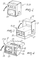
- a bidirectional earth-mover is generally designated by the reference numeral 10.
- the bidirectional earth-mover 10 is constituted by a chassis 11 with four wheels 12 supporting a control cabin 13 that internally accommodates a dashboard 14 and a driver's post constituted by a fold-down seat 15.
- the dashboard 14 and the seat 15 are jointly rotatable through 180 o about a vertical axis by means of a fifth wheel 16 or an equivalent bearing system rotatably coupled to the chassis 11.
- Four lamp clusters designated by the reference numerals 17 to 20, are furthermore supported on the chassis 11 and are arranged so as to form two pairs arranged mutually opposite in respective end regions of the bidirectional earth-mover 10 with respect to its longitudinal axis.
- the lamp clusters 17 and 18 that form one of the two pairs are arranged mutually opposite to the left and to the right, at the sides, of the bidirectional earth-mover 10.
- Each one of the lamp clusters 17 and 18 comprises a box-like body 21 that is substantially prism-shaped, except for a region 22 of its surface that is radiused; a white-light headlamp 23 for forward travel and an orange lamp 24 acting as an intermittent direction indicator are flush-mounted in said body along one of its surfaces, and a set of lamps 25, which comprises mutually integrated stop lights, direction indicator, and a rear reflector for reversing the travel direction, are flush-mounted in said body along another one of its surfaces, said surfaces being mutually perpendicular.
- the box-like body 21 is supported on the chassis 11 by pivoting to two wings 26 rigidly coupled to said chassis.
- the chassis 11 is furthermore radiused complementarily to the region 22 at the box-like body 21.
- the lamp clusters 19 and 20 constituting the other pair are identical and are arranged mutually opposite along the sides of the bidirectional earth-mover 10.
- Each one of the lamp clusters 19 and 20 is constituted by a box-like body 27 that is substantially prism-shaped and in which the following elements are flush-mounted along two mutually perpendicular surfaces: in a first surface, a white-light headlamp 28 and an orange lamp 29 for intermittent direction signalling, and in a second surface, a set of lamps 30 comprising mutually integrated stop lights, direction indicator, and rear reflector for reversing the travel direction.
- the box-like body 27 is connected to the chassis 11 by pivoting, about a substantially horizontal rotation axis, to two arms 31 of a C-shaped supporting element 32 that is in turn fixed to the chassis 11.
- a hydraulic circuit for moving the lamp clusters 17 to 20 is generally designated by the reference numeral 33.
- the hydraulic circuit 33 comprises a discharge tank 34 for the oil and a pump 35, which are provided with respective ducts connected to a slide-valve distributor 36 that is actuated mechanically and reverses the flows.
- actuators 37 are also connected to the slide-valve distributor 36, and each one actuates the movement of one of the lamp clusters 17 to 20.
- a button 38 controls the electrical activation of the sets of lamps 25 and 30, of the headlamps 23 and 28, and of the orange lamps 24 and 29 related to the lamp clusters 17 to 20 according to the travel condition of the bidirectional earth-mover 10 by circuital reversal of an electric circuit not shown in the figures, whereas a lever 39 mechanically actuates the slide-valve distributor 36, and therefore the movement of the lamp clusters 17 to 20, again according to said travel condition.
- the button 38 is located inside the cabin 13 and is actuatable automatically according to the position assumed by the seat 15.
- the seat 15 presses the button 38, it induces a consequent change in the electrical circuital status; in order to be turned, said seat must first be folded down towards the dashboard and then returned to its operating position.
- the lever 39 is located at the support of the seat 15.
- the lamp clusters 17 to 20 all rotate substantially about a horizontal axis and alternately conceal one of the sides of the respective box-like bodies 21 or 27 in which the headlamps and the lamps are installed.
- hydraulic circuit 33 is configured so that once the flow has been switched, there is a simultaneous switching of the position of the lamp clusters 17 to 20 into configurations, that are complementary according to a travel configuration, if considered in pairs.
- the materials employed, as well as the dimensions, may be any according to the requirements.
Landscapes
- Engineering & Computer Science (AREA)
- Mechanical Engineering (AREA)
- Lighting Device Outwards From Vehicle And Optical Signal (AREA)
- Consolidation Of Soil By Introduction Of Solidifying Substances Into Soil (AREA)
- Devices For Conveying Motion By Means Of Endless Flexible Members (AREA)
- Optical Communication System (AREA)
- Measuring Volume Flow (AREA)
- Lasers (AREA)
- Earth Drilling (AREA)
Applications Claiming Priority (2)
| Application Number | Priority Date | Filing Date | Title |
|---|---|---|---|
| IT94PD000161A IT1279515B1 (it) | 1994-09-13 | 1994-09-13 | Impianto ottico per macchine operatrici bidirezionali |
| ITPD940161 | 1994-09-13 |
Publications (3)
| Publication Number | Publication Date |
|---|---|
| EP0701922A2 true EP0701922A2 (de) | 1996-03-20 |
| EP0701922A3 EP0701922A3 (de) | 1996-08-21 |
| EP0701922B1 EP0701922B1 (de) | 1999-12-01 |
Family
ID=11390802
Family Applications (1)
| Application Number | Title | Priority Date | Filing Date |
|---|---|---|---|
| EP95114135A Expired - Lifetime EP0701922B1 (de) | 1994-09-13 | 1995-09-08 | Zweirichtungserdbewegungsmaschine |
Country Status (4)
| Country | Link |
|---|---|
| EP (1) | EP0701922B1 (de) |
| AT (1) | ATE187130T1 (de) |
| DE (1) | DE69513595D1 (de) |
| IT (1) | IT1279515B1 (de) |
Families Citing this family (1)
| Publication number | Priority date | Publication date | Assignee | Title |
|---|---|---|---|---|
| FR3096753A1 (fr) * | 2019-05-29 | 2020-12-04 | Valeo Vision | Dispositif lumineux de véhicule automobile |
Family Cites Families (3)
| Publication number | Priority date | Publication date | Assignee | Title |
|---|---|---|---|---|
| US4851970A (en) * | 1988-06-07 | 1989-07-25 | Bronder David G | Swing-away taillight assembly |
| US5195813A (en) * | 1991-09-03 | 1993-03-23 | Kc Hilites, Inc. | Wireless control for auxiliary lighting |
| US5171083A (en) * | 1991-09-10 | 1992-12-15 | Ltc Roll & Engineering Co. | Combined luggage rack and concealed lights for vehicle roof |
-
1994
- 1994-09-13 IT IT94PD000161A patent/IT1279515B1/it active IP Right Grant
-
1995
- 1995-09-08 AT AT95114135T patent/ATE187130T1/de not_active IP Right Cessation
- 1995-09-08 EP EP95114135A patent/EP0701922B1/de not_active Expired - Lifetime
- 1995-09-08 DE DE69513595T patent/DE69513595D1/de not_active Expired - Lifetime
Non-Patent Citations (1)
| Title |
|---|
| None |
Also Published As
| Publication number | Publication date |
|---|---|
| ITPD940161A1 (it) | 1996-03-13 |
| EP0701922A3 (de) | 1996-08-21 |
| IT1279515B1 (it) | 1997-12-16 |
| ITPD940161A0 (it) | 1994-09-13 |
| ATE187130T1 (de) | 1999-12-15 |
| EP0701922B1 (de) | 1999-12-01 |
| DE69513595D1 (de) | 2000-01-05 |
Similar Documents
| Publication | Publication Date | Title |
|---|---|---|
| US5682138A (en) | Illumination system for a semi-trailer or the like | |
| DE10007984A9 (de) | Leuchtvorrichtung für Fahrzeuge | |
| US5528218A (en) | Electronic self-canceling turn signal device | |
| WO2013000913A1 (de) | Nahbereich-kurvenlicht im aussenspiegel | |
| US5018593A (en) | High lift tag axle for trucks | |
| US7931285B2 (en) | Tag axle attachment for an off road agricultural applicator vehicle | |
| US5533584A (en) | Vehicle with front and rear steering | |
| EP0701922B1 (de) | Zweirichtungserdbewegungsmaschine | |
| DE4119436A1 (de) | Nutzfahrzeug mit ueblicher aussenspiegel-anordnung | |
| US4024497A (en) | Trailer protector light system | |
| DE102023102668A1 (de) | Anzeigevorrichtung für ein Fahrzeug | |
| JP2764195B2 (ja) | 退避するリアバンパーを備えた車輌 | |
| EP0485789B1 (de) | Vorrichtung zur Erfassung und optischen Anzeige des Einschlagwinkels eines gelenkten Rades eines Kraftfahrzeuges | |
| JP3315514B2 (ja) | 車両の突入防止装置 | |
| DE10120150C1 (de) | Richtungsweisende Zeigefunktion | |
| WO2005035307A1 (de) | Verfahren zur optimierung eines fahrzeuglichtes und scheinwerfervorrichtung | |
| JPH0525985Y2 (de) | ||
| JPH0711441U (ja) | 旋回作業車の側方照明装置 | |
| JP3398847B2 (ja) | 自動車用方向指示器及び非常点滅表示灯スイッチ | |
| KR0120318Y1 (ko) | 건설중장비의 작업등 방향제어 장치 | |
| JPH0314743A (ja) | 車両用ヘッドランプ装置 | |
| KR100449824B1 (ko) | 자동차비상등모드시의방향지시등작동장치 | |
| KR20220118577A (ko) | 산업차량용 워크램프 제어시스템 | |
| JPH0221976B2 (de) | ||
| JPH078350Y2 (ja) | 土木車両の換向装置 |
Legal Events
| Date | Code | Title | Description |
|---|---|---|---|
| PUAI | Public reference made under article 153(3) epc to a published international application that has entered the european phase |
Free format text: ORIGINAL CODE: 0009012 |
|
| AK | Designated contracting states |
Kind code of ref document: A2 Designated state(s): AT BE CH DE DK FR GB LI NL SE |
|
| PUAL | Search report despatched |
Free format text: ORIGINAL CODE: 0009013 |
|
| AK | Designated contracting states |
Kind code of ref document: A3 Designated state(s): AT BE CH DE DK FR GB LI NL SE |
|
| 17P | Request for examination filed |
Effective date: 19970122 |
|
| RAP1 | Party data changed (applicant data changed or rights of an application transferred) |
Owner name: ANTONIO CARRARO S.P.A. |
|
| GRAG | Despatch of communication of intention to grant |
Free format text: ORIGINAL CODE: EPIDOS AGRA |
|
| 17Q | First examination report despatched |
Effective date: 19981016 |
|
| GRAG | Despatch of communication of intention to grant |
Free format text: ORIGINAL CODE: EPIDOS AGRA |
|
| GRAG | Despatch of communication of intention to grant |
Free format text: ORIGINAL CODE: EPIDOS AGRA |
|
| GRAH | Despatch of communication of intention to grant a patent |
Free format text: ORIGINAL CODE: EPIDOS IGRA |
|
| GRAH | Despatch of communication of intention to grant a patent |
Free format text: ORIGINAL CODE: EPIDOS IGRA |
|
| GRAA | (expected) grant |
Free format text: ORIGINAL CODE: 0009210 |
|
| PUAC | Information related to the publication of a b1 document modified or deleted |
Free format text: ORIGINAL CODE: 0009299EPPU |
|
| STAA | Information on the status of an ep patent application or granted ep patent |
Free format text: STATUS: THE APPLICATION HAS BEEN WITHDRAWN |
|
| AK | Designated contracting states |
Kind code of ref document: B1 Designated state(s): AT BE CH DE DK FR GB LI NL SE |
|
| REF | Corresponds to: |
Ref document number: 187130 Country of ref document: AT Date of ref document: 19991215 Kind code of ref document: T |
|
| REG | Reference to a national code |
Ref country code: CH Ref legal event code: EP |
|
| REG | Reference to a national code |
Ref country code: CH Ref legal event code: PK |
|
| REF | Corresponds to: |
Ref document number: 69513595 Country of ref document: DE Date of ref document: 20000105 |
|
| 18W | Application withdrawn |
Withdrawal date: 19991109 |
|
| DB1 | Publication of patent cancelled | ||
| NLXE | Nl: other communications concerning ep-patents (part 3 heading xe) |
Free format text: PAT. BUL. 02/2000: PATENTNUMBER 0701922 SHOULD BE DELETED (SEE EUROPEAN PATENT BULLETIN 12.01.2000/02) |