EP0701963B2 - Motorhubwagen mit teleskopischem Arm - Google Patents
Motorhubwagen mit teleskopischem Arm Download PDFInfo
- Publication number
- EP0701963B2 EP0701963B2 EP95402069A EP95402069A EP0701963B2 EP 0701963 B2 EP0701963 B2 EP 0701963B2 EP 95402069 A EP95402069 A EP 95402069A EP 95402069 A EP95402069 A EP 95402069A EP 0701963 B2 EP0701963 B2 EP 0701963B2
- Authority
- EP
- European Patent Office
- Prior art keywords
- telescopic arm
- hydraulic
- pivotal shaft
- truck
- chassis
- Prior art date
- Legal status (The legal status is an assumption and is not a legal conclusion. Google has not performed a legal analysis and makes no representation as to the accuracy of the status listed.)
- Expired - Lifetime
Links
- 238000006073 displacement reaction Methods 0.000 description 10
- 238000011068 loading method Methods 0.000 description 8
- 238000010586 diagram Methods 0.000 description 4
- 230000000694 effects Effects 0.000 description 4
- 238000005553 drilling Methods 0.000 description 3
- 239000012530 fluid Substances 0.000 description 3
- 238000000034 method Methods 0.000 description 3
- 239000003381 stabilizer Substances 0.000 description 3
- 230000003068 static effect Effects 0.000 description 3
- 239000004606 Fillers/Extenders Substances 0.000 description 2
- 230000007423 decrease Effects 0.000 description 2
- 230000005484 gravity Effects 0.000 description 2
- 238000004519 manufacturing process Methods 0.000 description 2
- 238000012986 modification Methods 0.000 description 2
- 230000004048 modification Effects 0.000 description 2
- 238000007789 sealing Methods 0.000 description 2
- 238000002485 combustion reaction Methods 0.000 description 1
- 230000000295 complement effect Effects 0.000 description 1
- 238000010276 construction Methods 0.000 description 1
- 238000013461 design Methods 0.000 description 1
- 238000007599 discharging Methods 0.000 description 1
- 238000009826 distribution Methods 0.000 description 1
- 238000005304 joining Methods 0.000 description 1
- 238000012423 maintenance Methods 0.000 description 1
- 210000000056 organ Anatomy 0.000 description 1
- 238000005096 rolling process Methods 0.000 description 1
- 230000001360 synchronised effect Effects 0.000 description 1
- 238000013519 translation Methods 0.000 description 1
Images


Classifications
-
- B—PERFORMING OPERATIONS; TRANSPORTING
- B66—HOISTING; LIFTING; HAULING
- B66F—HOISTING, LIFTING, HAULING OR PUSHING, NOT OTHERWISE PROVIDED FOR, e.g. DEVICES WHICH APPLY A LIFTING OR PUSHING FORCE DIRECTLY TO THE SURFACE OF A LOAD
- B66F9/00—Devices for lifting or lowering bulky or heavy goods for loading or unloading purposes
- B66F9/06—Devices for lifting or lowering bulky or heavy goods for loading or unloading purposes movable, with their loads, on wheels or the like, e.g. fork-lift trucks
- B66F9/075—Constructional features or details
- B66F9/07563—Fork-lift trucks adapted to be carried by transport vehicles
-
- B—PERFORMING OPERATIONS; TRANSPORTING
- B66—HOISTING; LIFTING; HAULING
- B66F—HOISTING, LIFTING, HAULING OR PUSHING, NOT OTHERWISE PROVIDED FOR, e.g. DEVICES WHICH APPLY A LIFTING OR PUSHING FORCE DIRECTLY TO THE SURFACE OF A LOAD
- B66F9/00—Devices for lifting or lowering bulky or heavy goods for loading or unloading purposes
- B66F9/06—Devices for lifting or lowering bulky or heavy goods for loading or unloading purposes movable, with their loads, on wheels or the like, e.g. fork-lift trucks
- B66F9/065—Devices for lifting or lowering bulky or heavy goods for loading or unloading purposes movable, with their loads, on wheels or the like, e.g. fork-lift trucks non-masted
- B66F9/0655—Devices for lifting or lowering bulky or heavy goods for loading or unloading purposes movable, with their loads, on wheels or the like, e.g. fork-lift trucks non-masted with a telescopic boom
Definitions
- the invention relates to a handling trolley motorized, in particular of the kind capable of being taken on board the rear of a carrier vehicle.
- carts suitable to be loaded on a carrier vehicle such as a truck, which can be used for loading and unloading the truck and then be attached to the back of it to be so transported.
- This kind of cart is usually space-saving construction, so as to exceed truck from a short distance, its chassis made so that the front wheels are close to the front end of its loading fork.
- motorized handling trucks of the aforementioned type generally comprise a chassis having a U-shaped configuration open towards the front, fitted with two front wheels and a steerable rear wheel, so that the lifting means extend thus in their most retracted position between the branches sides of the U-shaped chassis.
- a general constraint for the design of truck mounted carts is that these carts should be as light as possible so as not to decrease notably the payload of the truck. That's the reason for which the on-board carts are generally free of counterweights and designed to so that the load is placed between the arms of wheels behind the front wheels of the carriage in position transport.
- Document US 4,826,474 describes a carriage motorized handling unit capable of being taken on board the back of a carrier vehicle, while the document EP 325064 describes a self-propelled forklift which is not suitable for being carried in the rear of a vehicle carrier.
- the carts embedded of known type are generally carried out in the form of a double-acting vertical mast carriage : this double-effect vertical mast allows handling and transport and also facilitates the loading of the trolley at the rear of the truck using a known technique for example according to document FR 2 298 454.
- the ancillary devices known for moving the forks at the front of the front wheels in the case of a load in front of the front wheels are of the type with telescopic forks, fork extender, or retractable mast.
- each telescopic fork has a sliding sleeve on a support guided by slides or rollers and driven by a cylinder synchronized with the deployment of the other fork.
- this provision leads to high manufacturing costs and significant maintenance costs for reliability relatively weak operation.
- a deformable scissor structure connects the vertical mast and the apron supporting the forks, thus displacing the forks horizontally forward during deformation of the scissor structure.
- This system presents on the one hand the disadvantage of increasing the overshoot total carriage at the rear of the truck, a corresponding distance to the length of the deformable structure at scissors in the folded position, which increases the length of the total rolling stock including the vehicle carrier and on-board cart, and presents other share the disadvantage of reducing the payload of the vehicle corresponding carrier of additional weight added by the presence of this deformable structure to scissors.
- the mast In retractable mast devices, the mast is mounted on a structure that slides inside the carriage chassis.
- This provision presents the same disadvantages as the extensor system of forks due to the fact that moving towards the front of the assembly comprising the mast and its structure carrier causes a significant shift towards the front of the truck's center of gravity, displacement resulting in a significant reduction in the capacity of load transport and static load stability on the spot.
- mast carts vertical which is not covered by the present invention, move the load-bearing forks sideways to position in correspondence with the charges to handle.
- Move side of the entire lifting structure comprising a vertical mast carrying one or more aprons can also be made relative to the supporting frame by appropriate means.
- the object of the invention is to remedy the drawbacks above from the prior art, by creating a new motorized handling trolley capable of being loaded in the rear of a carrier vehicle in a simple and fast.
- the invention also aims to apply the principle lateral displacement of the supporting structure trolley with telescopic arm, without significant increase of mechanical organ, while allowing exploitation presenting the same performances as those of prior art.
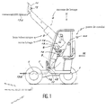
- a carriage according to the invention comprises a chassis 1 having a U-shaped configuration opening towards the front, a driving position 2, a powertrain 3 and lifting means 4.
- a branch 1a of the chassis carries a front wheel 5 while the other branch 1b carried the other front wheel 6.
- the rear steering wheel 7 is mounted substantially at the middle of the main body of the chassis. Rear wheel steering 7 is controlled by a steering wheel 8 located in the cockpit 2 which also includes all lifting means control members 4.
- the powertrain 3 is preferably a group comprising an internal combustion engine hydraulic pump, distribution and necessary command being grouped with the group powertrain 3 and controlled directly from the operator station 2.
- the lifting means 4 comprise a telescopic arm 9 pivotally mounted around a substantially horizontal axis 10 located at the rear of the chassis 1 substantially above the rear wheel director 7.
- the control and driving position is located on one side of the truck, the powertrain 3 is located on the side opposite the control and driving position, and the telescopic arm 9 in its lowered position and retracted corresponding to the transport of a load goes between operator station 2 and the powertrain 3.
- the telescopic arm 9 carries at its remote end of the pivot axis 10 a gripping member 11 swiveling around an axis horizontal 12 under the action of an actuating cylinder not shown and of a type known per se.
- the gripping member 11 is preferably shaped in an apron supporting forks 13a, 13b.
- the forks 13a, 13b can start from the lowered position and retracted from the telescopic arm 9 corresponding to the transport of a load and shown in solid lines, to move to other horizontal or tilted positions in a direction of digging or a direction of dumping shown in dotted lines.
- the telescopic arm 9 is extendable under the action an internal cylinder not shown and pivots under the action of a lifting cylinder 14 disposed laterally by relative to the arm and fixed to a bracket fixed to the beam of the telescopic arm 9.
- the trolley is advantageously fitted according to the invention of a compensation cylinder, able to maintain the forks 13a, 13b horizontal during the transport of the load in the event of movement of the carriage on rough terrain.
- the lifting cylinder 14 and the compensation cylinder 15 are mounted on the side and on the other side of the beam of the telescopic arm 9, in a position does not interfere with driver visibility when the telescopic arm 9 is in the transport position, fully lowered and retracted.
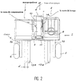
- all of the means of lifting 4 is movable transversely from a distance predetermined d so as to allow a precise adjustment of the positioning of the lifting when gripping the load.
- the lifting means 4 comprising the arm telescopic 9 are movable on the stroke d according to a controlled and preferably controlled movement hydraulically under the action of means of translation arranged in the vicinity of the pivot axis 10.
- the hydraulic actuation means have at least one hydraulic cylinder, the direction of actuation is substantially parallel to the pivot axis 10.
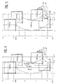
- a carriage according to the invention presents a stability diagram without stand corresponding to the lifting of a load of 9000 N at a distance of 1 meter in front of the front wheels: on thus obtains performances equivalent to or better than those of on-board art carts prior.
- the carts according to the invention have a significantly higher front wheel reach to carts of the prior art.
- Figure 5 shows a stability diagram with stand further improved compared to the diagram stability without stand in Figure 4 and by compared to the characteristics of the on-board carts of the prior art, in the case where a carriage is fitted according to the invention of retractable stabilizers 16 capable coming to rest on the ground in front of the point of contact P of a front wheel 5 with the ground.
- the retractable stabilizers 16 able to come in support on the ground in front of the contact points of front wheels 5 with the ground are fixed to the chassis 1 of the trolley according to the invention in a manner known in self for fixing stabilizers on trolleys embedded in the prior art and controlled so similar by an actuating cylinder exerting a substantially vertical thrust.
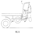
- a loading method of a trolley according to the invention and of joining to a carrier vehicle comprises the steps described below.
- the carriage then rests under the effect of its own weight on the support 21 on which it is applied by the telescopic arm in fully retracted position: the load loading equilibrium position according to the invention on board the rear of the carrier vehicle is perfectly stable and allows transport on long distances.
- a locking means is provided. complementary to the truck on board carrier vehicle with the support 21 secured to the vehicle carrier.
- This locking means can for example have two controlled side locks directly by means of a lever arranged in the truck control and control station 2. These side locks can be mechanical locks or hydraulically operated, or alternatively electric.
- the means of locking is controlled by stopping the carriage motor or the interruption of electrical power to the truck, or interruption of hydraulic power to the truck.
- the powertrain 3 can advantageously be constituted by an electric group operating on battery in the case of applications prohibiting the use of heat engines.
- a piston 30 integral with the pivot axis 10 of the telescopic arm is shown diagrammatically by its main beam 9.
- the piston 30 delimits two chambers 31a and 31b inside a jacket 32.
- a first drilling 33a practiced substantially coaxial with the pivot axis 10 and a second drilling 33b practiced substantially coaxially with pivot axis 10 allow feeding respectively of each chamber 31a or 31b in fluid hydraulic.
- the axis 10 is mounted integral with the chassis 1 via of two mounting parts 34a, 34b assembled to chassis 1 by screwing, for example of screws not exceeding 35a, 35b, or by any other means allowing the establishment of the pivot axis 10 and the passage of the piston 30 through an orifice of diameter provided for this effect.
- the shirt 32 is closed at its ends by two closure rings 38a, 38b carrying seals sealing rings, the rings 38a, 38b being fixed in a manner known per se by screwing or by means equivalent.
- the structure thus described has a conformation in double rod cylinder, in which the piston 30 is fixed and the shirt 32 moves in the first direction when the chamber 31a is put under hydraulic pressure and in a second direction opposite to said first sense when chamber 31b is pressurized hydraulic.
- a person skilled in the art can thus determine without difficulty a transverse displacement travel d in function internal dimensions of the jacket 32 and the width of the piston 30 remaining stationary relative to the axis pivot 10 and relative to chassis 1 of the carriage elevator.
- each support socket 36a or 36b is integral with a bracket 37a or 37b which is itself connected to the main beam of the lifting arm telescopic carriage according to the invention.
- the invention makes it possible to carry out in a simple manner lateral movement which does not hamper pivoting of the telescopic arm, the means of movement lateral allowing the arm to pivot simultaneously telescopic around the substantially horizontal axis 10.
- a piston 40 is integral with the pivot axis 10 of the telescopic arm shown diagrammatically by its main beam 9.
- the piston 40 delimits two chambers 41a and 41b inside a jacket 42.
- two supply orifices are produced or for discharging hydraulic fluids 43a, 43b directly in the shirt 42.
- Such tapped holes 43a, 43b of hydraulic fluid supply are type known per se and does not require description more detailed.
- the axis 10 is mounted integral with the chassis 1 via of two mounting parts 44a, 44b assembled to chassis 1 for example by screwing, screws not exceeding 45a, 45b, or by any other means allowing the establishment of the pivot axis 10 and the passage of the piston 40 through an orifice of diameter provided at this effect.
- the shirt 42 is closed at its ends by two closure rings 48a, 48b carrying seals suitable sealing, the rings 48a, 48b being fixed in a manner known per se by screwing or by means equivalent.
- the structure thus described has a conformation in double rod cylinder, in which the piston 40 is fixed and the shirt 42 moves in a first direction when the chamber 41 a is put under hydraulic pressure and in a second direction opposite to said first direction when chamber 41b is pressurized hydraulic.
- a person skilled in the art can thus determine without difficulty a transverse displacement travel d in function of the internal dimensions of the jacket 42 and of the width of the piston 40 remaining stationary relative to the axis pivot 10 and relative to chassis 1 of the carriage elevator.
- each support sleeve 46a or 46b is integral with a bracket 47a or 47b which is itself connected to the main beam of the lifting arm telescopic carriage according to the invention.
- the invention makes it possible to carry out in a simple manner lateral movement which does not hamper pivoting of the telescopic arm, the means of movement lateral allowing the arm to pivot simultaneously telescopic around the substantially horizontal axis 10.
Landscapes
- Engineering & Computer Science (AREA)
- Transportation (AREA)
- Structural Engineering (AREA)
- Civil Engineering (AREA)
- Life Sciences & Earth Sciences (AREA)
- Geology (AREA)
- Mechanical Engineering (AREA)
- Forklifts And Lifting Vehicles (AREA)
- Handcart (AREA)
Claims (6)
- Transportkarren mit einer Antriebseinheit und einem Teleskoparm sowie einem auf einer Mehrzahl von Rädern angeordneten Fahrgestell, wovon wenigstens ein Rad angetrieben ist und das eine Antriebseinheit, eine Kabine und Hubeinrichtungen, die zwischen der Antriebseinheit und der Kabine angeordnet sind, trägt, wobei die Hubeinrichtungen den um eine im wesentlichen waagerechte Achse schwenkbar angeordneten Teleskoparm umfassen, dadurch gekennzeichnet, daß die den Teleskoparm (5) aufweisenden Hubeinrichtungen (4) quer verschiebbar sind, um ein genaues Einstellen der Hubeinrichtungen über eine vorgebbare Strecke (D) zum Aufnehmem einer Last zu erreichen und daß der Teleskoparm (9) in Querrichtung auf seiner Schwenkachse (10) unter der Wirkung von Betätigungsmitteln, die in der Nähe der Schwenkachse (10) angeordnet sind, verschiebbar ist.
- Transportkarren nach Anspruch 1, dadurch gekennzeichnet, daß die Betätigungsmittel aus hydraulischen Betätigungsmitteln mit wenigstens einer Hydraulik-Kolben-Zylinder-Einheit bestehen, deren Wirkungsrichtung im wesentlichen parallel zur Schwenkachse (10) des Teleskoparms (9) verläuft.
- Transportkarren nach Anspruch 1 oder 2, dadurch gekennzeichnet, daß die Betätigungsmittel im wesentlichen koaxial zur Schwenkachse (10) des Teleskoparms (9) angeordnet sind.
- Transportkarren nach einem der Ansprüche 1 bis 3, dadurch gekennzeichnet, daß die Betätigungsmittel doppelt wirkend sind.
- Transportkarren nach einem der Ansprüche 1 bis 4, dadurch gekennzeichnet, daß die Betätigungsmittel aus hydraulischen Mitteln bestehen, die durch im wesentlichen parallel oder koaxial zur Schwenkachse (10) verlaufende Öffnungen beaufschlagt werden.
- Transportkarren nach einem der Ansprüche 1 bis 4, dadurch gekennzeichnet, daß die Betätigungsmittel aus hydraulischen Mitteln bestehen, die durch im wesentlichen senkrecht zur Schwenkachse (10) verlaufende Öffnungen beaufschlagt werden.
Applications Claiming Priority (4)
| Application Number | Priority Date | Filing Date | Title |
|---|---|---|---|
| FR9410953A FR2724374B1 (fr) | 1994-09-14 | 1994-09-14 | Chariot de manutention motorise apte a etre embarque a l'arriere d'un vehicule porteur |
| FR9410953 | 1994-09-14 | ||
| FR9500033A FR2728884A1 (fr) | 1995-01-04 | 1995-01-04 | Chariot de manutention motorise a bras telescopique |
| FR9500033 | 1995-01-04 |
Publications (3)
| Publication Number | Publication Date |
|---|---|
| EP0701963A1 EP0701963A1 (de) | 1996-03-20 |
| EP0701963B1 EP0701963B1 (de) | 1998-02-04 |
| EP0701963B2 true EP0701963B2 (de) | 2004-08-18 |
Family
ID=26231398
Family Applications (1)
| Application Number | Title | Priority Date | Filing Date |
|---|---|---|---|
| EP95402069A Expired - Lifetime EP0701963B2 (de) | 1994-09-14 | 1995-09-13 | Motorhubwagen mit teleskopischem Arm |
Country Status (4)
| Country | Link |
|---|---|
| US (1) | US5813821A (de) |
| EP (1) | EP0701963B2 (de) |
| CA (1) | CA2158232C (de) |
| DE (2) | DE69501578T3 (de) |
Cited By (1)
| Publication number | Priority date | Publication date | Assignee | Title |
|---|---|---|---|---|
| CN104444969A (zh) * | 2014-11-26 | 2015-03-25 | 王马达 | 一种保障简易叉车随集装箱运行的吊运及固定设备及使用该设备的方法 |
Families Citing this family (14)
| Publication number | Priority date | Publication date | Assignee | Title |
|---|---|---|---|---|
| FR2750970A1 (fr) * | 1996-07-12 | 1998-01-16 | Fdi Sambron | Chariot de manutention comprenant un dispositif de protection du cariste |
| DE59707518D1 (de) * | 1997-11-04 | 2002-07-18 | Schaeff Karl Gmbh & Co | Auf Rädern fahrbares querbewegliches Arbeitsgerät |
| DE69800866T2 (de) * | 1998-04-17 | 2001-11-15 | Liftcon Technologies Ltd., Shannon | Transportabler Gabelhubwagen mit teleskopischem Hebearm |
| US6293579B1 (en) | 1999-03-08 | 2001-09-25 | Karl Schaeff Gmbh & Co Maschinenfabrik | Mobile rig on wheels with transverse motion |
| FR2837809B1 (fr) | 2002-03-29 | 2004-11-12 | Manitou Bf | Chariot elevateur a portee variable a trois roues |
| ES2271763T3 (es) * | 2003-11-17 | 2007-04-16 | Moffett Research And Development Limited | Carretilla de horquilla elevadora. |
| US8087868B2 (en) * | 2004-01-13 | 2012-01-03 | Moffett Research And Development Limited | Forklift truck for mounting on the rear of a carrying vehicle with a fork side shifting attachment |
| US8308417B1 (en) | 2008-12-18 | 2012-11-13 | Joseph Verrochi | Method and system for transporting, loading, and unloading various types of goods |
| EP3152149B1 (de) * | 2014-06-05 | 2018-11-28 | Combilift | Containerlader/-entlader |
| GB2543317A (en) * | 2015-10-14 | 2017-04-19 | Cargotec Res & Dev Ireland Ltd | A Truck mounted forklift |
| CN110088406A (zh) * | 2016-12-16 | 2019-08-02 | 克拉克设备公司 | 具有伸缩式提升臂的装载机 |
| GB2572356B (en) | 2018-03-27 | 2022-09-14 | Bamford Excavators Ltd | Load-handling vehicle |
| CN109704237B (zh) * | 2019-01-16 | 2020-09-04 | 安徽宇锋智能科技有限公司 | 一种具有智能判定识别感知功能的agv牵引叉车 |
| US12454209B2 (en) * | 2021-04-29 | 2025-10-28 | Hol-Mac Corporation | Truck carried forklift mounting system |
Citations (8)
| Publication number | Priority date | Publication date | Assignee | Title |
|---|---|---|---|---|
| GB1487904A (en) † | 1975-01-21 | 1977-10-05 | Kooi Bv | Lorry with an attachment for an accompanying fork-lift truck |
| US4147263A (en) † | 1977-01-06 | 1979-04-03 | Lull Engineering Company, Inc. | High lift loader with extended transfer |
| US4396341A (en) † | 1981-07-14 | 1983-08-02 | Brouwer Turf Equipment Limited | Apparatus for mounting a forklift vehicle on a carrier vehicle |
| WO1989000972A1 (en) † | 1987-07-27 | 1989-02-09 | Merlo S.P.A. Industria Metalmeccanica | A lifting truck with a telescopic lifting arm |
| US4964788A (en) † | 1990-03-21 | 1990-10-23 | Tecumseh Products Company | Hermetic terminal with terminal pin assemblies having fusible links and motor compressor unit including same |
| EP0410082A1 (de) † | 1989-07-27 | 1991-01-30 | Kidde Industries Inc. | Gabelstapler mit einem teleskopischen Hilfsarm, verbunden mit einem teleskopischen Hauptarm |
| EP0569277A1 (de) † | 1992-05-07 | 1993-11-10 | Manitou Bf | Elektrischer Hubwagen mit einem teleskopischen Arm |
| EP0577388A2 (de) † | 1992-06-30 | 1994-01-05 | Caterpillar Inc. | Erdbewegungsmaschine |
Family Cites Families (20)
| Publication number | Priority date | Publication date | Assignee | Title |
|---|---|---|---|---|
| US2731162A (en) * | 1953-11-19 | 1956-01-17 | Superior Separator Company | Loader with self-leveling carrier |
| US3243053A (en) * | 1964-11-13 | 1966-03-29 | Deere & Co | Backhoe |
| US3407947A (en) * | 1965-12-22 | 1968-10-29 | Antonio Valla & C S N C | Material-moving device for moving objects |
| US3688929A (en) * | 1970-09-30 | 1972-09-05 | Skagit Corp | Lift truck with rotatable carriage |
| US3754673A (en) * | 1971-12-13 | 1973-08-28 | Clark Equipment Co | Detachable fork for lift trucks |
| US3799379A (en) * | 1973-01-26 | 1974-03-26 | T Grether | Fork lift |
| US3836025A (en) * | 1973-05-21 | 1974-09-17 | Loed Corp | Material-handling machine |
| JPS5339681B2 (de) * | 1974-11-14 | 1978-10-23 | ||
| NL165992C (nl) * | 1975-01-21 | 1981-06-15 | Kooi Bv | Vorkheftruck. |
| GB1525923A (en) * | 1975-10-09 | 1978-09-27 | Liner Concrete Machinery | Load handling vehicle with load engaging means |
| DE2739537A1 (de) * | 1976-09-03 | 1978-03-09 | Loed Corp | Schwenkgabelanordnung fuer verladeausruestungen |
| DE2716704A1 (de) * | 1977-04-15 | 1978-10-19 | Kaup Gmbh & Co Kg | Seitenschieber fuer einen hublader |
| WO1982001363A1 (en) * | 1980-10-16 | 1982-04-29 | David W Lutz | Lift and carry truck |
| US4674944A (en) * | 1985-12-27 | 1987-06-23 | Kidde, Inc. | Forklift variable reach mechanism |
| US4688982A (en) * | 1986-08-01 | 1987-08-25 | Smart Robert L | Motorized operator unit for manually adjustable fork mechanism |
| US4848010A (en) * | 1987-07-27 | 1989-07-18 | Zimmerman Harold M | Backhoe machine |
| US4826474A (en) * | 1987-12-14 | 1989-05-02 | Butterworth Jetting Systems, Inc. | Forklift apparatus for unloading articles from an elevated surface |
| FR2624842B1 (fr) * | 1987-12-18 | 1990-04-06 | Manitou Bf | Amelioration a la stabilite des chariots elevateurs a bras telescopique |
| GB2253831A (en) * | 1991-03-20 | 1992-09-23 | Gcm 600 Ltd | Load handling vehicle |
| US5113969A (en) * | 1991-05-10 | 1992-05-19 | Centre De Recherche Industrielle Du Quebec | Displaceable working platform with extensible boom |
-
1995
- 1995-09-13 CA CA002158232A patent/CA2158232C/fr not_active Expired - Lifetime
- 1995-09-13 DE DE69501578T patent/DE69501578T3/de not_active Expired - Lifetime
- 1995-09-13 DE DE0701963T patent/DE701963T1/de active Pending
- 1995-09-13 EP EP95402069A patent/EP0701963B2/de not_active Expired - Lifetime
- 1995-09-14 US US08/528,300 patent/US5813821A/en not_active Expired - Lifetime
Patent Citations (8)
| Publication number | Priority date | Publication date | Assignee | Title |
|---|---|---|---|---|
| GB1487904A (en) † | 1975-01-21 | 1977-10-05 | Kooi Bv | Lorry with an attachment for an accompanying fork-lift truck |
| US4147263A (en) † | 1977-01-06 | 1979-04-03 | Lull Engineering Company, Inc. | High lift loader with extended transfer |
| US4396341A (en) † | 1981-07-14 | 1983-08-02 | Brouwer Turf Equipment Limited | Apparatus for mounting a forklift vehicle on a carrier vehicle |
| WO1989000972A1 (en) † | 1987-07-27 | 1989-02-09 | Merlo S.P.A. Industria Metalmeccanica | A lifting truck with a telescopic lifting arm |
| EP0410082A1 (de) † | 1989-07-27 | 1991-01-30 | Kidde Industries Inc. | Gabelstapler mit einem teleskopischen Hilfsarm, verbunden mit einem teleskopischen Hauptarm |
| US4964788A (en) † | 1990-03-21 | 1990-10-23 | Tecumseh Products Company | Hermetic terminal with terminal pin assemblies having fusible links and motor compressor unit including same |
| EP0569277A1 (de) † | 1992-05-07 | 1993-11-10 | Manitou Bf | Elektrischer Hubwagen mit einem teleskopischen Arm |
| EP0577388A2 (de) † | 1992-06-30 | 1994-01-05 | Caterpillar Inc. | Erdbewegungsmaschine |
Cited By (1)
| Publication number | Priority date | Publication date | Assignee | Title |
|---|---|---|---|---|
| CN104444969A (zh) * | 2014-11-26 | 2015-03-25 | 王马达 | 一种保障简易叉车随集装箱运行的吊运及固定设备及使用该设备的方法 |
Also Published As
| Publication number | Publication date |
|---|---|
| US5813821A (en) | 1998-09-29 |
| DE69501578T2 (de) | 1998-09-17 |
| EP0701963A1 (de) | 1996-03-20 |
| EP0701963B1 (de) | 1998-02-04 |
| CA2158232C (fr) | 2001-08-07 |
| CA2158232A1 (fr) | 1996-03-15 |
| DE701963T1 (de) | 1996-12-12 |
| DE69501578D1 (de) | 1998-03-12 |
| DE69501578T3 (de) | 2005-02-03 |
Similar Documents
| Publication | Publication Date | Title |
|---|---|---|
| EP0701963B2 (de) | Motorhubwagen mit teleskopischem Arm | |
| CA2879172C (fr) | Essieu et vehicule comprenant au moins un tel essieu | |
| CA2585850C (fr) | Chariot de manutention a au moins trois roues directrices | |
| EP0905083B1 (de) | Wagen mit Hubmast, geeignet zur Montage an das Ende eines Transportfahrzeugs | |
| FR2800363A1 (fr) | Chariot elevateur a fourche | |
| EP1476343B1 (de) | Hebevorrichtung sowie sackkarre | |
| EP0325064B1 (de) | Verbesserung der Stabilität von Gabelhubwagen mit einem teleskopischen Arm | |
| FR2607076A1 (fr) | Vehicule, notamment chariot de manutention | |
| FR2615157A1 (fr) | Tracteur perfectionne notamment pour semi-remorque | |
| EP0490798A2 (de) | Kran, insbesondere für die Handhabung | |
| FR2496034A1 (fr) | Nouvel appareil de manutention du genre diable | |
| FR2791049A1 (fr) | Porte equipement pour engin de levage, mat d'un engin de levage comprenant un tel porte equipement et engin de levage tel que chariot a fourches pourvu dudit mat | |
| FR2750125A1 (fr) | Chariot elevateur pour preparation de commandes | |
| FR2759998A1 (fr) | Engin porte-outil pour le transport, la manutention et l'execution de travaux avec des outils | |
| FR2724374A1 (fr) | Chariot de manutention motorise apte a etre embarque a l'arriere d'un vehicule porteur | |
| FR2765865A1 (fr) | Vehicule de manutention de materiaux | |
| FR3067707B1 (fr) | Transpalette | |
| FR2728884A1 (fr) | Chariot de manutention motorise a bras telescopique | |
| FR2987795A1 (fr) | Ensemble de manutention destine a equiper un chassis d'un vehicule, pour la pose, la depose et/ou le bennage et le transport de tout type de conteneur | |
| FR2867175A1 (fr) | Chariot elevateur comportant au moins un element amortisseur | |
| FR2580563A1 (fr) | Dispositif pour manipuler une charge notamment pour vehicules de transport | |
| FR2570655A1 (fr) | Vehicule, notamment chariot de manutention | |
| WO2012085640A1 (fr) | Ensemble de transporte constitué d'un tracteur motorisé et d'un mobile monté sur roues | |
| FR2698063A1 (fr) | Chariot porte-palettes. | |
| FR2755681A1 (fr) | Chariot elevateur a dispositif de stabilisateur |
Legal Events
| Date | Code | Title | Description |
|---|---|---|---|
| PUAI | Public reference made under article 153(3) epc to a published international application that has entered the european phase |
Free format text: ORIGINAL CODE: 0009012 |
|
| AK | Designated contracting states |
Kind code of ref document: A1 Designated state(s): DE FR GB IE IT NL |
|
| 17P | Request for examination filed |
Effective date: 19960418 |
|
| IECL | Ie: translation for ep claims filed | ||
| DET | De: translation of patent claims | ||
| 17Q | First examination report despatched |
Effective date: 19970424 |
|
| GRAG | Despatch of communication of intention to grant |
Free format text: ORIGINAL CODE: EPIDOS AGRA |
|
| GRAG | Despatch of communication of intention to grant |
Free format text: ORIGINAL CODE: EPIDOS AGRA |
|
| GRAH | Despatch of communication of intention to grant a patent |
Free format text: ORIGINAL CODE: EPIDOS IGRA |
|
| GRAH | Despatch of communication of intention to grant a patent |
Free format text: ORIGINAL CODE: EPIDOS IGRA |
|
| GRAA | (expected) grant |
Free format text: ORIGINAL CODE: 0009210 |
|
| AK | Designated contracting states |
Kind code of ref document: B1 Designated state(s): DE FR GB IE IT NL |
|
| PG25 | Lapsed in a contracting state [announced via postgrant information from national office to epo] |
Ref country code: IT Free format text: LAPSE BECAUSE OF FAILURE TO SUBMIT A TRANSLATION OF THE DESCRIPTION OR TO PAY THE FEE WITHIN THE PRE;WARNING: LAPSES OF ITALIAN PATENTS WITH EFFECTIVE DATE BEFORE 2007 MAY HAVE OCCURRED AT ANY TIME BEFORE 2007. THE CORRECT EFFECTIVE DATE MAY BE DIFFERENT FROM THE ONE RECORDED.SCRIBED TIME-LIMIT Effective date: 19980204 |
|
| REF | Corresponds to: |
Ref document number: 69501578 Country of ref document: DE Date of ref document: 19980312 |
|
| GBT | Gb: translation of ep patent filed (gb section 77(6)(a)/1977) |
Effective date: 19980429 |
|
| PLBQ | Unpublished change to opponent data |
Free format text: ORIGINAL CODE: EPIDOS OPPO |
|
| PLBI | Opposition filed |
Free format text: ORIGINAL CODE: 0009260 |
|
| PLBQ | Unpublished change to opponent data |
Free format text: ORIGINAL CODE: EPIDOS OPPO |
|
| PLBI | Opposition filed |
Free format text: ORIGINAL CODE: 0009260 |
|
| 26 | Opposition filed |
Opponent name: TRANSMANUT Effective date: 19981022 |
|
| 26 | Opposition filed |
Opponent name: MOFFETT ENGINEERING LIMITED Effective date: 19981103 Opponent name: TRANSMANUT Effective date: 19981022 |
|
| PLBF | Reply of patent proprietor to notice(s) of opposition |
Free format text: ORIGINAL CODE: EPIDOS OBSO |
|
| NLR1 | Nl: opposition has been filed with the epo |
Opponent name: TRANSMANUT |
|
| NLR1 | Nl: opposition has been filed with the epo |
Opponent name: MOFFETT ENGINEERING LIMITED Opponent name: TRANSMANUT |
|
| PLBF | Reply of patent proprietor to notice(s) of opposition |
Free format text: ORIGINAL CODE: EPIDOS OBSO |
|
| PG25 | Lapsed in a contracting state [announced via postgrant information from national office to epo] |
Ref country code: FR Free format text: LAPSE BECAUSE OF NON-PAYMENT OF DUE FEES Effective date: 19990531 |
|
| REG | Reference to a national code |
Ref country code: FR Ref legal event code: ST |
|
| REG | Reference to a national code |
Ref country code: GB Ref legal event code: IF02 |
|
| PLBO | Opposition rejected |
Free format text: ORIGINAL CODE: EPIDOS REJO |
|
| APAC | Appeal dossier modified |
Free format text: ORIGINAL CODE: EPIDOS NOAPO |
|
| APAC | Appeal dossier modified |
Free format text: ORIGINAL CODE: EPIDOS NOAPO |
|
| APBU | Appeal procedure closed |
Free format text: ORIGINAL CODE: EPIDOSNNOA9O |
|
| PUAH | Patent maintained in amended form |
Free format text: ORIGINAL CODE: 0009272 |
|
| STAA | Information on the status of an ep patent application or granted ep patent |
Free format text: STATUS: PATENT MAINTAINED AS AMENDED |
|
| 27A | Patent maintained in amended form |
Effective date: 20040818 |
|
| AK | Designated contracting states |
Kind code of ref document: B2 Designated state(s): DE FR GB IE IT NL |
|
| NLR2 | Nl: decision of opposition |
Effective date: 20040818 |
|
| GBTA | Gb: translation of amended ep patent filed (gb section 77(6)(b)/1977) | ||
| APAA | Appeal reference recorded |
Free format text: ORIGINAL CODE: EPIDOS REFN |
|
| NLR3 | Nl: receipt of modified translations in the netherlands language after an opposition procedure | ||
| APAH | Appeal reference modified |
Free format text: ORIGINAL CODE: EPIDOSCREFNO |
|
| PLAB | Opposition data, opponent's data or that of the opponent's representative modified |
Free format text: ORIGINAL CODE: 0009299OPPO |
|
| PGFP | Annual fee paid to national office [announced via postgrant information from national office to epo] |
Ref country code: IE Payment date: 20140918 Year of fee payment: 20 Ref country code: DE Payment date: 20140922 Year of fee payment: 20 |
|
| PGFP | Annual fee paid to national office [announced via postgrant information from national office to epo] |
Ref country code: GB Payment date: 20140919 Year of fee payment: 20 |
|
| REG | Reference to a national code |
Ref country code: DE Ref legal event code: R082 Ref document number: 69501578 Country of ref document: DE Representative=s name: BUNGARTZ CHRISTOPHERSEN PARTNERSCHAFT MBB PATE, DE |
|
| PGFP | Annual fee paid to national office [announced via postgrant information from national office to epo] |
Ref country code: NL Payment date: 20140918 Year of fee payment: 20 |
|
| REG | Reference to a national code |
Ref country code: DE Ref legal event code: R071 Ref document number: 69501578 Country of ref document: DE |
|
| REG | Reference to a national code |
Ref country code: NL Ref legal event code: MK Effective date: 20150912 |
|
| REG | Reference to a national code |
Ref country code: GB Ref legal event code: PE20 Expiry date: 20150912 |
|
| PG25 | Lapsed in a contracting state [announced via postgrant information from national office to epo] |
Ref country code: GB Free format text: LAPSE BECAUSE OF EXPIRATION OF PROTECTION Effective date: 20150912 |
|
| REG | Reference to a national code |
Ref country code: IE Ref legal event code: MK9A |
|
| PG25 | Lapsed in a contracting state [announced via postgrant information from national office to epo] |
Ref country code: IE Free format text: LAPSE BECAUSE OF EXPIRATION OF PROTECTION Effective date: 20150913 |