EP0702184A1 - Anneau de retenue - Google Patents
Anneau de retenue Download PDFInfo
- Publication number
- EP0702184A1 EP0702184A1 EP94306729A EP94306729A EP0702184A1 EP 0702184 A1 EP0702184 A1 EP 0702184A1 EP 94306729 A EP94306729 A EP 94306729A EP 94306729 A EP94306729 A EP 94306729A EP 0702184 A1 EP0702184 A1 EP 0702184A1
- Authority
- EP
- European Patent Office
- Prior art keywords
- ring
- grab ring
- teeth
- grab
- annular
- Prior art date
- Legal status (The legal status is an assumption and is not a legal conclusion. Google has not performed a legal analysis and makes no representation as to the accuracy of the status listed.)
- Granted
Links
Images


Classifications
-
- F—MECHANICAL ENGINEERING; LIGHTING; HEATING; WEAPONS; BLASTING
- F16—ENGINEERING ELEMENTS AND UNITS; GENERAL MEASURES FOR PRODUCING AND MAINTAINING EFFECTIVE FUNCTIONING OF MACHINES OR INSTALLATIONS; THERMAL INSULATION IN GENERAL
- F16B—DEVICES FOR FASTENING OR SECURING CONSTRUCTIONAL ELEMENTS OR MACHINE PARTS TOGETHER, e.g. NAILS, BOLTS, CIRCLIPS, CLAMPS, CLIPS OR WEDGES; JOINTS OR JOINTING
- F16B21/00—Means for preventing relative axial movement of a pin, spigot, shaft or the like and a member surrounding it; Stud-and-socket releasable fastenings
- F16B21/10—Means for preventing relative axial movement of a pin, spigot, shaft or the like and a member surrounding it; Stud-and-socket releasable fastenings by separate parts
- F16B21/20—Means for preventing relative axial movement of a pin, spigot, shaft or the like and a member surrounding it; Stud-and-socket releasable fastenings by separate parts for bolts or shafts without holes, grooves, or notches for locking members
-
- F—MECHANICAL ENGINEERING; LIGHTING; HEATING; WEAPONS; BLASTING
- F16—ENGINEERING ELEMENTS AND UNITS; GENERAL MEASURES FOR PRODUCING AND MAINTAINING EFFECTIVE FUNCTIONING OF MACHINES OR INSTALLATIONS; THERMAL INSULATION IN GENERAL
- F16L—PIPES; JOINTS OR FITTINGS FOR PIPES; SUPPORTS FOR PIPES, CABLES OR PROTECTIVE TUBING; MEANS FOR THERMAL INSULATION IN GENERAL
- F16L37/00—Couplings of the quick-acting type
- F16L37/08—Couplings of the quick-acting type in which the connection between abutting or axially overlapping ends is maintained by locking members
- F16L37/084—Couplings of the quick-acting type in which the connection between abutting or axially overlapping ends is maintained by locking members combined with automatic locking
- F16L37/0845—Couplings of the quick-acting type in which the connection between abutting or axially overlapping ends is maintained by locking members combined with automatic locking by means of retaining members associated with the packing member
-
- F—MECHANICAL ENGINEERING; LIGHTING; HEATING; WEAPONS; BLASTING
- F16—ENGINEERING ELEMENTS AND UNITS; GENERAL MEASURES FOR PRODUCING AND MAINTAINING EFFECTIVE FUNCTIONING OF MACHINES OR INSTALLATIONS; THERMAL INSULATION IN GENERAL
- F16L—PIPES; JOINTS OR FITTINGS FOR PIPES; SUPPORTS FOR PIPES, CABLES OR PROTECTIVE TUBING; MEANS FOR THERMAL INSULATION IN GENERAL
- F16L37/00—Couplings of the quick-acting type
- F16L37/08—Couplings of the quick-acting type in which the connection between abutting or axially overlapping ends is maintained by locking members
- F16L37/084—Couplings of the quick-acting type in which the connection between abutting or axially overlapping ends is maintained by locking members combined with automatic locking
- F16L37/091—Couplings of the quick-acting type in which the connection between abutting or axially overlapping ends is maintained by locking members combined with automatic locking by means of a ring provided with teeth or fingers
Definitions
- the invention relates to grab rings.
- Grab rings are commonly used in a wide variety of applications where it is required to couple cylindrical components in a bore of another component.
- a grab ring is mounted on the components and has projecting teeth around its periphery angled to engage with a component, the teeth being arranged so that the cylindrical component can be engaged in the bore in one direction but not extracted.
- This invention provides a grab ring comprising an annular element having one set of teeth projecting outwardly at an inclined angle to the annular element to one side thereof and a second set of teeth projecting inwardly at an inclined angle to the annular element to the other side thereof to engage between a pair of inner and outer concentric cylindrical surfaces to permit relative movement between the surfaces in one direction whilst preventing relative movement in the opposite direction.
- the grab ring according to the invention has the advantage that it does not have to be mounted on one or other of the components which the ring is to hold together.
- the annular element lies in a radial plane having radially spaced inner and outer edges, one set of teeth projecting outwardly from the outer edge of the element and angled to the radial plane of the element to one side thereof and the other set of teeth projecting inwardly of the inner edge of the annular element and being angled to the opposite side of the annular plane of the element.
- the teeth maybe of generally rectangular shape or the teeth may have radial edges.
- a multiplicity of teeth may be provided at spaced locations around said edges of the annular elements.
- teeth may be located in pairs directly opposite one another around the edges of the annular element.
- the grab ring may be embodied in an annular sealing element with the ends of the teeth of the grab ring projecting from the surface of the seal.
- the ring may be embodied in a resilient sleeve mid-way along the sleeve with one set of teeth projecting outwardly of the sleeve, the outer periphery of the sleeve having annular sealing ribs to one side of the grab ring and the inner periphery of the sleeve having inner sealing ribs to the other side of the grab ring.
- the ring may have a radial slot through the ring at one location in its periphery to enable the ring to be opened radially for mounting in a radial direction on a pipe or tube.
- a grab ring formed in a a hard spring steel and comprising a flat annular element 10 lying in a radial plane and having inner and outer edges 11, 12.
- the inner edge has a multiplicity of equi-spaced integral generally rectangular profile teeth 13 projecting inwardly and to one side of the plane of the annular element and the outer periphery 12 of the element has a corresponding set of integral generally rectangular teeth 14 formed opposite the teeth 13 and projecting outwardly to the other side of the element.
- the inner teeth 13 provide inwardly facing edges 15 to engage and bite into the surface of a component with the grab ring and the outer teeth 14 provide outwardly facing edges 16 to engage and bite into a surface encircling the grab ring.
- the side edges of the teeth extend radially of the annular element so that the teeth taper slightly towards their outer ends.
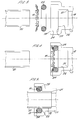
- the grab ring according to the invention has a wide variety of applications and is particularly suitable for locking a tube in a coupling body with a seal if required to form a sealed joint. Such an arrangement is illustrated in Figure 3 to 5 which reference will now be made.
- a coupling body 17 has a throughway 18 which is open at one end 19 of the coupling body to receive an end part of a tube 20 to be fixed and sealed in the coupling body.
- the throughway 18 is of smaller diameter than the tube 20 and to accommodate the tube is increased in diameter of step 21 to a bore 22 in which the tube 20 is a close fit.
- the bore 22 is increased in diameter again at a step 23 adjacent the open end of the throughway to form an open socket 24.
- the socket receives an "O" ring seal 25 to seal between the socket and tube 20 and also the grab ring for locking the tube in the socket.
- the grab ring is dimensioned so that the outer teeth bear against and bit into the surface of the socket 24 and the inner teeth bear against and bite into the surface of the tube 20.
- the inner teeth 13 of the grab ring are angled into the throughway to allow the tube 20 to be inserted through the grab ring into the bore 22 to engage the shoulder 21 as shown in Figure 5.
- the teeth bite into the surface of the tube to hold it in place.
- the seal 25 is trapped between the grab ring and shoulder 23 and is thereby held in sealing engagement between the encircling surface of the socket, the shoulder 23 and the outer surface of the tube.
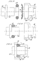
- Figures 6 to 8 of the drawings show a similar arrangement in which the grab ring is embodied in the seal 25 with the annular element 10 of the ring disposed at the centre of the seal and the teeth 13, 14 projecting from the surface of the seal.
- the arrangement is otherwise similar to that of Figure 3 to 5.
- FIG. 9 A further similar arrangement is shown in Figures 9 to 11 in which the tube 20 is formed with a encircling bead 26.
- the seal 25 is inserted in the end of the tube against the bead 26 and the grab ring is then located on the tube to hold the seal against the bead.
- the resulting assembly is then inserted in the socket 24 at the open end of the throughway with a tube 20 projecting into the bore 22 and the outer periphery of the grab ring engaging the inner surface of the socket to retain the assembly in the socket.
- Figure 12 shows a modified form of the grab ring in which a radial slot indicated at 30 is cut through the ring to allow the ring to be opened by flexing the ends of the ring away from each other to enable the ring to be engaged around a tube in a radial direction.
- Figures 13 to 15 show an assembly similar to that as Figures 9 to 11 referred to above in which the grab ring is illustrated as being engaged on the end of the tube 13 in a radial direction in Figure 13.
- the grab ring is assembled on the end of the tube against the bead 26, the seal is then located on the end of the tube as shown in Figure 14 and the assembly is inserted in the socket.
- Figures 16 to 18 show a similar arrangement in which the tube 20 has a pair of spaced beads 31, 32 adjacent to its end and the grab ring is assembled on the tube between the beads.
- the seal is located against the bead 32 adjacent the end of the tube.
- the bead 32 is of larger diameter than bead 31 to be a close fit in socket 24 to retain the seal in the socket when subject to pressure.
- Figure 19 shows part of a socket for a coupling body in which two grab rings both embodied in resilient seals are mounted to receive and engage a tube.
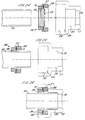
- Figure 20 shows a further arrangement in which a grab ring is embodied in a stepped thick walled resilient sleeve 35 having a larger diameter portion 36 to one side of the grab ring and the smaller diameter portion 37 to the other side.
- the larger diameter portion 36 extends partway up the outwardly projecting teeth 14 and is formed with a pair of encircling ribs 37.
- the outwardly projecting teeth 14 of the grab ring are arranged to lock the grab ring/sleeve in a bore and the encircling ribs 37 form a seal with the bore.
- the smaller diameter portion 37 of the sleeve to the other side of the grab ring extends partway up the inwardly projected teeth of the grab ring and is formed with a pair of obliquely angled annular sealing elements 38 facing in the opposite direction to the teeth 30 to seal with a surface of a tube extending through the sleeve/grab ring assembly.
- Figure 21 of the drawings shows a coupling body and tube similar to that of Figures 3 to 5 referred to above with a sleeve/grab ring arrangement of Figure 20 for securing and sealing the tube in the coupling body.
- the sleeve/grab ring assembly has been inserted in the socket 24 of the coupling body 17, the outwardly projecting teeth 14 holding the assembly in the socket and the encircling ribs 37 sealing with the surface of the socket.
- the tube 20 can then be inserted through the angled seals 38 around the inner periphery of the sleeve and through the teeth 13 of the grab ring into the bore 22 formed in the socket for the tube.
- the teeth 13 hold the tube against withdrawal and the seals 38 form a sealing engagement with the surface of the tube as can be seen in Figure 23.
- Figures 24 to 26 show a similar sequence in which the sleeve/grab ring is assembled on the tube 21 and the tube/sleeve assembly is inserted in the socket in the coupling body.
Landscapes
- Engineering & Computer Science (AREA)
- General Engineering & Computer Science (AREA)
- Mechanical Engineering (AREA)
- Quick-Acting Or Multi-Walled Pipe Joints (AREA)
- Gasket Seals (AREA)
- Hooks, Suction Cups, And Attachment By Adhesive Means (AREA)
- Table Equipment (AREA)
- Chairs For Special Purposes, Such As Reclining Chairs (AREA)
Priority Applications (5)
| Application Number | Priority Date | Filing Date | Title |
|---|---|---|---|
| EP94306729A EP0702184B1 (fr) | 1994-09-14 | 1994-09-14 | Anneau de retenue |
| DE69424282T DE69424282T2 (de) | 1994-09-14 | 1994-09-14 | Klemmring |
| EP99121691A EP0972981A3 (fr) | 1994-09-14 | 1994-09-14 | Anneau de retenue |
| ES94306729T ES2145104T3 (es) | 1994-09-14 | 1994-09-14 | Anillo de mordaza. |
| US08/528,203 US5603530A (en) | 1994-09-14 | 1995-09-14 | Grab rings |
Applications Claiming Priority (1)
| Application Number | Priority Date | Filing Date | Title |
|---|---|---|---|
| EP94306729A EP0702184B1 (fr) | 1994-09-14 | 1994-09-14 | Anneau de retenue |
Related Child Applications (1)
| Application Number | Title | Priority Date | Filing Date |
|---|---|---|---|
| EP99121691A Division EP0972981A3 (fr) | 1994-09-14 | 1994-09-14 | Anneau de retenue |
Publications (2)
| Publication Number | Publication Date |
|---|---|
| EP0702184A1 true EP0702184A1 (fr) | 1996-03-20 |
| EP0702184B1 EP0702184B1 (fr) | 2000-05-03 |
Family
ID=8217846
Family Applications (2)
| Application Number | Title | Priority Date | Filing Date |
|---|---|---|---|
| EP99121691A Withdrawn EP0972981A3 (fr) | 1994-09-14 | 1994-09-14 | Anneau de retenue |
| EP94306729A Expired - Lifetime EP0702184B1 (fr) | 1994-09-14 | 1994-09-14 | Anneau de retenue |
Family Applications Before (1)
| Application Number | Title | Priority Date | Filing Date |
|---|---|---|---|
| EP99121691A Withdrawn EP0972981A3 (fr) | 1994-09-14 | 1994-09-14 | Anneau de retenue |
Country Status (4)
| Country | Link |
|---|---|
| US (1) | US5603530A (fr) |
| EP (2) | EP0972981A3 (fr) |
| DE (1) | DE69424282T2 (fr) |
| ES (1) | ES2145104T3 (fr) |
Cited By (11)
| Publication number | Priority date | Publication date | Assignee | Title |
|---|---|---|---|---|
| FR2768475A1 (fr) * | 1997-09-12 | 1999-03-19 | Magneti Marelli France | Dispositif de retenue axiale d'un organe dans son support |
| EP1036970A3 (fr) * | 1999-03-17 | 2001-09-12 | Delta Capillary Products Limited | Connecteur à fixation par pression |
| EP1209404A1 (fr) * | 2000-11-28 | 2002-05-29 | FESTO AG & Co | Dispositif de raccord pour une conduit de fluid |
| WO2006045592A1 (fr) * | 2004-10-25 | 2006-05-04 | Enno Meyer | Manchon d'element de raccordement de tubes, et element de raccordement de tubes |
| EP1655529A1 (fr) * | 2004-11-08 | 2006-05-10 | Kulm Holding Ag | Raccord rapide |
| US7758085B2 (en) | 2007-12-03 | 2010-07-20 | John Guest International Limited | Tube couplings |
| DE102014225280A1 (de) | 2014-12-09 | 2016-06-09 | Festo Ag & Co. Kg | Anschlussvorrichtung für eine Fluidleitung |
| DE102014225279A1 (de) | 2014-12-09 | 2016-06-09 | Festo Ag & Co. Kg | Anschlussvorrichtung für eine Fluidleitung |
| US10487969B2 (en) * | 2014-09-26 | 2019-11-26 | Ips, Corporation-Weld-On Division | Pipe fitting apparatus and methods |
| CN111997891A (zh) * | 2020-09-10 | 2020-11-27 | 康斯克泵业(苏州)有限公司 | 一种液压泵吸油管的插接机构 |
| US12422064B2 (en) | 2022-10-27 | 2025-09-23 | IPS, Corporation—Weld-On Division | Pipe fittings and assemblies |
Families Citing this family (89)
| Publication number | Priority date | Publication date | Assignee | Title |
|---|---|---|---|---|
| GB9115850D0 (en) * | 1991-07-23 | 1991-09-04 | Univ Manchester | Coupling |
| GB9816537D0 (en) * | 1998-07-29 | 1998-09-30 | Guest John D | Tube coupling devices |
| DE10007424A1 (de) * | 2000-02-18 | 2001-08-23 | Magenwirth Gmbh Co Gustav | Vorrichtung und Verfahren zum druckdichten Anschließen einer Leitung |
| US7108289B1 (en) | 2000-06-08 | 2006-09-19 | United States Pipe And Foundry Company, Llc | Restraining gasket for mechanical joints of pipes |
| US7104573B2 (en) * | 2000-06-08 | 2006-09-12 | United States Pipe And Foundy Company, Llc | Energized restraining gasket for mechanical joints of pipes |
| US6499771B1 (en) | 2000-07-18 | 2002-12-31 | Victaulic Company Of America | Mechanical pipe coupling with toothed retainer |
| US20060265852A1 (en) * | 2001-01-19 | 2006-11-30 | Victaulic Company | Triple-expanded mechanical pipe coupling derived from a standard fitting |
| US6913292B2 (en) | 2001-01-19 | 2005-07-05 | Victaulic Company Of America | Mechanical pipe coupling derived from a standard fitting |
| US20040239115A1 (en) * | 2001-01-19 | 2004-12-02 | Victaulic Company Of America | Mechanical pipe coupling derived from a standard fitting |
| US7121593B2 (en) * | 2001-01-19 | 2006-10-17 | Victaulic Company | Triple-expanded mechanical pipe coupling derived from a standard fitting |
| US7500699B2 (en) * | 2001-01-19 | 2009-03-10 | Victaulic Company | Clamping mechanical pipe coupling derived from a standard fitting |
| US20050146133A1 (en) * | 2001-01-19 | 2005-07-07 | Victaulic Company Of America | Mechanical pipe coupling derived from a standard fitting |
| US6488319B2 (en) * | 2001-04-26 | 2002-12-03 | Jim Jones | Self restrained pressure gasket |
| US6765143B2 (en) * | 2001-07-09 | 2004-07-20 | Bridgeport Fittings, Inc. | Tubing and conduit coupling or connector assembly |
| US20060083600A1 (en) * | 2001-09-28 | 2006-04-20 | Yao Zhao | Fastening apparatus and a special tool thereof |
| US6688652B2 (en) * | 2001-12-12 | 2004-02-10 | U.S. Pipe And Foundry Company | Locking device and method for securing telescoped pipe |
| US6595556B1 (en) | 2002-03-14 | 2003-07-22 | Minature Precision Components, Inc. | Cartridge-type quick connector |
| US6719330B2 (en) * | 2002-06-18 | 2004-04-13 | Qest | Flexible tubing/fitting connection |
| WO2004013525A2 (fr) * | 2002-07-31 | 2004-02-12 | Pentapure Incorporated | Assemblage d'un tuyau |
| USD481110S1 (en) | 2002-12-16 | 2003-10-21 | Victaulic Company Of America | Tee coupling |
| USD482103S1 (en) | 2002-12-16 | 2003-11-11 | Victaulic Company Of America | Elbow coupling |
| USD483441S1 (en) | 2002-12-16 | 2003-12-09 | Victaulic Company Of America | Pipe coupling |
| USD483095S1 (en) | 2002-12-16 | 2003-12-02 | Victaulic Company Of America | Pipe coupling |
| USD481447S1 (en) | 2002-12-16 | 2003-10-28 | Victaulic Company Of America | Elbow coupling |
| USD480787S1 (en) | 2002-12-16 | 2003-10-14 | Victaulic Company Of America | Elbow coupling |
| USD480786S1 (en) | 2002-12-16 | 2003-10-14 | Victaulic Company Of America | Tee coupling |
| USD483094S1 (en) | 2002-12-16 | 2003-12-02 | Victaulic Company Of America | Pipe coupling |
| USD481109S1 (en) | 2002-12-16 | 2003-10-21 | Victaulic Company Of America | Tee coupling |
| ES2257605T3 (es) * | 2003-01-24 | 2006-08-01 | Sedus Stoll Ag | Union de enchufe. |
| US7156423B2 (en) * | 2003-04-11 | 2007-01-02 | 3M Innovative Properties Company | Plastic tube joint |
| US20050040650A1 (en) * | 2003-08-18 | 2005-02-24 | Chang Tuan Hsu | Easy assembled tube connector |
| WO2005031174A2 (fr) * | 2003-09-25 | 2005-04-07 | United States Pipe And Foundry Company, Llc | Bague de compression a torsion centroide pour raccords de tuyaux |
| DE10344435B4 (de) * | 2003-09-25 | 2006-06-01 | Autoliv Development Ab | Selbstsperrender Gurtaufroller |
| US7207606B2 (en) * | 2004-04-19 | 2007-04-24 | United States Pipe And Foundry Company, Llc | Mechanical pipe joint, gasket, and method for restraining pipe spigots in mechanical pipe joint bell sockets |
| DE202004007290U1 (de) * | 2004-05-07 | 2005-09-15 | Viega Gmbh & Co Kg | Dichtelement |
| US8657299B2 (en) | 2004-07-15 | 2014-02-25 | John E. Rode | Mounting rings for shafts |
| USD517666S1 (en) | 2004-08-20 | 2006-03-21 | Victaulic Company | Elbow coupling |
| USD516686S1 (en) | 2004-08-20 | 2006-03-07 | Victaulic Company | Tee coupling |
| USD517665S1 (en) | 2004-08-20 | 2006-03-21 | Victaulic Company | Pipe coupling |
| GB0421808D0 (en) * | 2004-10-01 | 2004-11-03 | Imi Norgren Ltd | Coupling device |
| US7341286B2 (en) * | 2004-12-09 | 2008-03-11 | Cooper Standard Automotive, Inc. | Fluid coupling with dual function retention ring |
| US7455330B2 (en) * | 2005-04-28 | 2008-11-25 | Kulm Holding Ag | Quick coupling |
| MX2008000304A (es) | 2005-07-03 | 2008-04-07 | Widee Bv | Acoplamiento entre dos tubos con pinzas colocadas separadas. |
| WO2007004859A1 (fr) | 2005-07-03 | 2007-01-11 | Widee B.V. | Accouplement entre deux corps |
| NL1029412C2 (nl) | 2005-07-03 | 2007-01-08 | Widee Bv | Koppeling tussen twee lichamen. |
| CA2614127A1 (fr) | 2005-07-03 | 2007-01-11 | Widee B.V. | Accouplement entre deux tubes |
| BRPI0520420A2 (pt) | 2005-07-03 | 2009-05-05 | Widee Bv | acoplamento entre dois corpos compreendendo um anel de corte elasticamente deformável com uma rosca de parafuso formando bordas de corte |
| PL1962009T3 (pl) * | 2007-02-01 | 2012-05-31 | Conex Uniwersal Ltd | Zespół łącznika rurowego i sposób jego wykonania |
| JP2009185960A (ja) * | 2008-02-08 | 2009-08-20 | Yamatake Corp | 流体整流器及びこれを用いた流量計 |
| US9188260B2 (en) * | 2008-08-01 | 2015-11-17 | Nibco Inc. | Crimp evident seal |
| US20100171302A1 (en) * | 2009-01-05 | 2010-07-08 | Nibco Inc. | Push-twist connector |
| US20110214886A1 (en) * | 2010-03-05 | 2011-09-08 | The Viking Corporation | Push On Threadless Sprinkler And Fitting |
| US9689517B2 (en) | 2010-09-23 | 2017-06-27 | Republic Conduit, Inc. | Tool-free metal conduit connector and related methods |
| KR101375718B1 (ko) * | 2011-02-21 | 2014-03-20 | 삼성전자주식회사 | 냉매관의 연결구조 및 이를 포함하는 공기조화기 |
| US9395024B2 (en) | 2011-11-21 | 2016-07-19 | Victaulic Company | Coupling having gasket pocket of varying depth |
| US8820795B2 (en) | 2012-02-02 | 2014-09-02 | Victaulic Company | Fitting for joining pipe elements |
| US9182058B2 (en) | 2012-02-08 | 2015-11-10 | Victaulic Company | Fitting having receptacle of varying depth |
| DE102012210471B4 (de) * | 2012-06-21 | 2014-12-04 | Robert Bosch Gmbh | Federkralle zur radialen und axialen Fixierung rotationssymmetrischer Elemente |
| FR2995651B1 (fr) * | 2012-09-19 | 2015-05-01 | Saint Gobain Pont A Mousson | Ensemble d'etancheite pour jonction tubulaire et jonction tubulaire correspondante |
| WO2014071025A1 (fr) * | 2012-10-31 | 2014-05-08 | Prabhat Industries | Dispositif de retenue de tuyau |
| US8801048B2 (en) | 2012-11-27 | 2014-08-12 | Charlotte Pipe And Foundry Company | Mechanical pipe coupling assembly without adhesive or bonding agent |
| US20150000019A1 (en) * | 2013-06-28 | 2015-01-01 | Darrell Gregoy Connell | Self-Sealing Closet Flange |
| US10294648B2 (en) | 2013-06-28 | 2019-05-21 | Darrell Gregory Connell | Toilet flange that can be rotated during insertion having a gripping ring and a durable safety seal |
| JP6347530B2 (ja) | 2013-07-17 | 2018-06-27 | ビクターリック カンパニー | 弧状剛性リブを有する継手 |
| CN103419766B (zh) * | 2013-08-07 | 2015-06-24 | 京西重工(上海)有限公司 | 真空助力器反应杆保持器及反应杆保持方法 |
| KR101509979B1 (ko) * | 2013-11-21 | 2015-04-07 | 동부대우전자 주식회사 | 수도꼭지와 급수호스 간의 연결장치 |
| US9541228B2 (en) | 2013-12-11 | 2017-01-10 | Nibco Inc. | Push-to-connect fitting |
| US9447906B2 (en) * | 2013-12-11 | 2016-09-20 | Nibco Inc. | Self-locking push-to-connect insert |
| US10006575B2 (en) | 2013-12-11 | 2018-06-26 | Nibco Inc. | Modular push-to-connect assembly |
| US9777875B2 (en) | 2014-02-26 | 2017-10-03 | Nibco Inc. | Clam shell push-to-connect assembly |
| CN105179837B (zh) | 2014-06-03 | 2019-11-05 | 机械工业股份公司 | 用于运送气体、压缩空气、和其他流体的导管的连接接头 |
| GB2532809A (en) * | 2015-04-09 | 2016-06-01 | Pegler Yorkshire Group Ltd | Seal |
| US10161551B2 (en) | 2015-07-09 | 2018-12-25 | A. Raymond Et Cie | Quick-connector |
| US10330228B2 (en) | 2015-08-31 | 2019-06-25 | Ingersoll-Rand Company | Pipe connection fitting |
| EP3150876A1 (fr) * | 2015-09-29 | 2017-04-05 | Siemens Aktiengesellschaft | Fixation d'encodeur destine a fixer un arbre d'encodeur sur un arbre d'entrainement et procede |
| US9903515B2 (en) * | 2015-12-09 | 2018-02-27 | Victaulic Company | Seal with lip projections |
| DE102016205621B3 (de) * | 2016-04-05 | 2017-03-23 | Festo Ag & Co. Kg | Anschlussvorrichtung für eine Fluidleitung und diesbezügliches Montageverfahren |
| US11275096B2 (en) * | 2017-09-28 | 2022-03-15 | Bioceryx Technologies Inc. | Blood transfer devices and methods thereof |
| FR3074875B1 (fr) | 2017-12-08 | 2020-04-17 | Dualsun | Dispositif de raccordement fluidique d'echangeurs thermiques d'au moins deux panneaux solaires hybrides |
| US10727630B2 (en) | 2018-03-20 | 2020-07-28 | Mts Sensor Technologie Gmbh & Co. Kg | Connecting device |
| US12060954B2 (en) | 2019-03-26 | 2024-08-13 | Nibco Inc. | Piping component and sealing element for insertion therein |
| EP3951231B1 (fr) * | 2019-03-29 | 2024-01-31 | Proterial, Ltd. | Élément de retenue et raccord de tuyau l'utilisant |
| US11149426B2 (en) | 2019-06-12 | 2021-10-19 | Charlotte Pipe And Foundry Company | Toilet assembly having improved closet flange |
| DE202019004256U1 (de) | 2019-10-15 | 2021-01-19 | Schwan-Stabilo Cosmetics Gmbh & Co. Kg | Stift |
| DE102019007166A1 (de) * | 2019-10-15 | 2021-04-15 | Schwan-Stabilo Cosmetics Gmbh & Co. Kg | Stift |
| EP3842678A1 (fr) * | 2019-12-26 | 2021-06-30 | Hsin Cheng Kuo | Connecteur de tuyau |
| DE102020109786A1 (de) | 2020-04-08 | 2021-10-14 | Mts Sensor Technologie Gmbh & Co. Kg | Anschlusseinrichtung |
| CN113970019A (zh) * | 2020-07-22 | 2022-01-25 | 浙江浩海管业有限公司 | 一种钢圈 |
| US12442475B2 (en) * | 2025-03-13 | 2025-10-14 | Xiamen Tongjie Technology., Ltd | Push type conduit joint release structure |
Citations (6)
| Publication number | Priority date | Publication date | Assignee | Title |
|---|---|---|---|---|
| US3007726A (en) * | 1959-12-03 | 1961-11-07 | United Carr Fastener Corp | Fastening devices |
| US3483789A (en) * | 1967-11-20 | 1969-12-16 | Waldes Kohinoor Inc | Self-locking retaining rings |
| US4073514A (en) * | 1976-05-26 | 1978-02-14 | Indian Head Inc. | Combination pipe fitting and retainer ring |
| GB1550624A (en) * | 1976-06-17 | 1979-08-15 | British Steel Corp | Pipe joints and pipe couplings |
| US4586734A (en) * | 1982-12-08 | 1986-05-06 | General Industries, Inc. | Pipe joint assembly |
| EP0265065A2 (fr) * | 1986-10-23 | 1988-04-27 | The Gates Rubber Company | Raccord rapide |
Family Cites Families (16)
| Publication number | Priority date | Publication date | Assignee | Title |
|---|---|---|---|---|
| US1965273A (en) * | 1926-04-24 | 1934-07-03 | Wilson Rings Company | Sealing and locking device |
| US2147353A (en) * | 1938-06-04 | 1939-02-14 | Albert J Scholtes | Spread tongue hose coupling |
| US2201372A (en) * | 1938-11-26 | 1940-05-21 | Vernon Tool Co Ltd | Pipe coupling |
| CH445800A (de) * | 1966-12-08 | 1967-10-31 | Tuflex Ag | Vorrichtung zum Befestigen von Teilen, insbesondere von Tür- und Fensterrahmen, an einer Wand |
| US3582112A (en) * | 1969-04-14 | 1971-06-01 | Francisco A Pico | Fluid pressure-sealed pipe coupling |
| FR2102518A5 (fr) * | 1970-08-06 | 1972-04-07 | Lecuyer Daniel | |
| GB1448446A (en) * | 1972-10-31 | 1976-09-08 | Fosroc Ag | Bolt anchoring devices |
| NL7404779A (nl) * | 1974-04-08 | 1975-10-10 | Air O Mulder Bv | Koppelstrip. |
| US3976314A (en) * | 1975-01-03 | 1976-08-24 | Paul M. Hankison | Tube coupler |
| DE2628508A1 (de) * | 1976-06-25 | 1977-12-29 | Hilti Ag | Schwenkmutter mit zwei u-foermigen scheiben |
| FR2547369B1 (fr) * | 1983-06-09 | 1986-10-24 | Morin Jacques | Dispositif de fixation murale |
| US4593943A (en) * | 1983-08-23 | 1986-06-10 | Kabushiki Kaisha Nihon Pisco | Tubing joint |
| US4676533A (en) * | 1984-11-13 | 1987-06-30 | Tolo, Inc. | Reversible lock and seal apparatus |
| DE3710852C1 (de) * | 1987-04-01 | 1988-03-10 | Rasmussen Gmbh | Rohrkupplung |
| JPH073119Y2 (ja) * | 1989-11-20 | 1995-01-30 | シーケーディ株式会社 | 管継手 |
| US5295697A (en) * | 1992-11-04 | 1994-03-22 | United States Pipe And Foundry Company | Restraining element for pressure pipe joints |
-
1994
- 1994-09-14 EP EP99121691A patent/EP0972981A3/fr not_active Withdrawn
- 1994-09-14 ES ES94306729T patent/ES2145104T3/es not_active Expired - Lifetime
- 1994-09-14 DE DE69424282T patent/DE69424282T2/de not_active Expired - Fee Related
- 1994-09-14 EP EP94306729A patent/EP0702184B1/fr not_active Expired - Lifetime
-
1995
- 1995-09-14 US US08/528,203 patent/US5603530A/en not_active Expired - Lifetime
Patent Citations (6)
| Publication number | Priority date | Publication date | Assignee | Title |
|---|---|---|---|---|
| US3007726A (en) * | 1959-12-03 | 1961-11-07 | United Carr Fastener Corp | Fastening devices |
| US3483789A (en) * | 1967-11-20 | 1969-12-16 | Waldes Kohinoor Inc | Self-locking retaining rings |
| US4073514A (en) * | 1976-05-26 | 1978-02-14 | Indian Head Inc. | Combination pipe fitting and retainer ring |
| GB1550624A (en) * | 1976-06-17 | 1979-08-15 | British Steel Corp | Pipe joints and pipe couplings |
| US4586734A (en) * | 1982-12-08 | 1986-05-06 | General Industries, Inc. | Pipe joint assembly |
| EP0265065A2 (fr) * | 1986-10-23 | 1988-04-27 | The Gates Rubber Company | Raccord rapide |
Cited By (13)
| Publication number | Priority date | Publication date | Assignee | Title |
|---|---|---|---|---|
| FR2768475A1 (fr) * | 1997-09-12 | 1999-03-19 | Magneti Marelli France | Dispositif de retenue axiale d'un organe dans son support |
| WO1999014508A1 (fr) * | 1997-09-12 | 1999-03-25 | Magneti Marelli France | Dispositif de retenue axiale d'un organe dans son support |
| EP1036970A3 (fr) * | 1999-03-17 | 2001-09-12 | Delta Capillary Products Limited | Connecteur à fixation par pression |
| EP1209404A1 (fr) * | 2000-11-28 | 2002-05-29 | FESTO AG & Co | Dispositif de raccord pour une conduit de fluid |
| WO2006045592A1 (fr) * | 2004-10-25 | 2006-05-04 | Enno Meyer | Manchon d'element de raccordement de tubes, et element de raccordement de tubes |
| EP1655529A1 (fr) * | 2004-11-08 | 2006-05-10 | Kulm Holding Ag | Raccord rapide |
| US7758085B2 (en) | 2007-12-03 | 2010-07-20 | John Guest International Limited | Tube couplings |
| US10487969B2 (en) * | 2014-09-26 | 2019-11-26 | Ips, Corporation-Weld-On Division | Pipe fitting apparatus and methods |
| US11486527B2 (en) | 2014-09-26 | 2022-11-01 | IPS, Corporation—Weld-On Division | Methods of forming a pipe joint between a pipe section and a pipe fitting |
| DE102014225280A1 (de) | 2014-12-09 | 2016-06-09 | Festo Ag & Co. Kg | Anschlussvorrichtung für eine Fluidleitung |
| DE102014225279A1 (de) | 2014-12-09 | 2016-06-09 | Festo Ag & Co. Kg | Anschlussvorrichtung für eine Fluidleitung |
| CN111997891A (zh) * | 2020-09-10 | 2020-11-27 | 康斯克泵业(苏州)有限公司 | 一种液压泵吸油管的插接机构 |
| US12422064B2 (en) | 2022-10-27 | 2025-09-23 | IPS, Corporation—Weld-On Division | Pipe fittings and assemblies |
Also Published As
| Publication number | Publication date |
|---|---|
| EP0972981A2 (fr) | 2000-01-19 |
| EP0972981A3 (fr) | 2000-04-26 |
| ES2145104T3 (es) | 2000-07-01 |
| DE69424282D1 (de) | 2000-06-08 |
| DE69424282T2 (de) | 2000-11-02 |
| US5603530A (en) | 1997-02-18 |
| EP0702184B1 (fr) | 2000-05-03 |
Similar Documents
| Publication | Publication Date | Title |
|---|---|---|
| US5603530A (en) | Grab rings | |
| US6086118A (en) | Quick connect tubing connector | |
| US5593188A (en) | Quick connect tubing connector and method of assembly | |
| US5813705A (en) | Snap-action pipe coupling retainer | |
| CA1195712A (fr) | Raccord pour tubes plastiques isolants a nervures annulaires | |
| US7841629B2 (en) | Plug-in coupling for fluidic systems | |
| CN1322263C (zh) | 可转动的快速连接器 | |
| CA1073497A (fr) | Raccord rapide | |
| US6334634B1 (en) | Push-to-connect tubing fitting | |
| US4832378A (en) | Fluid duct coupling and snap clip therefor | |
| US20050184518A1 (en) | Connector assembly for male and female members | |
| US10415728B2 (en) | Seal for a pipe coupling | |
| EP0537217A1 (fr) | Raccord de tuyaux | |
| GB1569351A (en) | Snap insertion pipe joint | |
| EP1126207A2 (fr) | Raccord en plastique moulée avec une membrane d'étanchéité | |
| JPH06502709A (ja) | 内側及び外側アームを備える抜け止めリング | |
| EP0785386B1 (fr) | Raccord de tuyaux | |
| EP0735306A2 (fr) | Raccords pour tuyaux | |
| US6899354B2 (en) | Pipe joining assembly | |
| EP0703397A1 (fr) | Raccord de fixation pour un tube annelé | |
| JPS62101993A (ja) | 管継手 | |
| JP2002071064A (ja) | 下水管路用耐震継手 | |
| JPH0544632Y2 (fr) | ||
| EP0599533A1 (fr) | Joint annulaire | |
| JPS5833437B2 (ja) | パイプの連結装置 |
Legal Events
| Date | Code | Title | Description |
|---|---|---|---|
| PUAI | Public reference made under article 153(3) epc to a published international application that has entered the european phase |
Free format text: ORIGINAL CODE: 0009012 |
|
| AK | Designated contracting states |
Kind code of ref document: A1 Designated state(s): DE ES FR GB IT |
|
| AX | Request for extension of the european patent |
Free format text: SI |
|
| RAX | Requested extension states of the european patent have changed |
Free format text: SI |
|
| RBV | Designated contracting states (corrected) |
Designated state(s): DE ES FR GB IT |
|
| 17P | Request for examination filed |
Effective date: 19960806 |
|
| 17Q | First examination report despatched |
Effective date: 19981116 |
|
| GRAG | Despatch of communication of intention to grant |
Free format text: ORIGINAL CODE: EPIDOS AGRA |
|
| RTI1 | Title (correction) |
Free format text: GRAB RING |
|
| GRAG | Despatch of communication of intention to grant |
Free format text: ORIGINAL CODE: EPIDOS AGRA |
|
| GRAH | Despatch of communication of intention to grant a patent |
Free format text: ORIGINAL CODE: EPIDOS IGRA |
|
| DAX | Request for extension of the european patent (deleted) | ||
| GRAH | Despatch of communication of intention to grant a patent |
Free format text: ORIGINAL CODE: EPIDOS IGRA |
|
| GRAA | (expected) grant |
Free format text: ORIGINAL CODE: 0009210 |
|
| AK | Designated contracting states |
Kind code of ref document: B1 Designated state(s): DE ES FR GB IT |
|
| REF | Corresponds to: |
Ref document number: 69424282 Country of ref document: DE Date of ref document: 20000608 |
|
| ET | Fr: translation filed | ||
| REG | Reference to a national code |
Ref country code: ES Ref legal event code: FG2A Ref document number: 2145104 Country of ref document: ES Kind code of ref document: T3 |
|
| ITF | It: translation for a ep patent filed | ||
| PLBE | No opposition filed within time limit |
Free format text: ORIGINAL CODE: 0009261 |
|
| STAA | Information on the status of an ep patent application or granted ep patent |
Free format text: STATUS: NO OPPOSITION FILED WITHIN TIME LIMIT |
|
| 26N | No opposition filed | ||
| REG | Reference to a national code |
Ref country code: GB Ref legal event code: IF02 |
|
| PGFP | Annual fee paid to national office [announced via postgrant information from national office to epo] |
Ref country code: ES Payment date: 20070905 Year of fee payment: 14 |
|
| PGFP | Annual fee paid to national office [announced via postgrant information from national office to epo] |
Ref country code: GB Payment date: 20070918 Year of fee payment: 14 |
|
| PGFP | Annual fee paid to national office [announced via postgrant information from national office to epo] |
Ref country code: IT Payment date: 20070921 Year of fee payment: 14 Ref country code: DE Payment date: 20071126 Year of fee payment: 14 |
|
| PGFP | Annual fee paid to national office [announced via postgrant information from national office to epo] |
Ref country code: FR Payment date: 20070816 Year of fee payment: 14 |
|
| REG | Reference to a national code |
Ref country code: FR Ref legal event code: TP |
|
| GBPC | Gb: european patent ceased through non-payment of renewal fee |
Effective date: 20080914 |
|
| REG | Reference to a national code |
Ref country code: FR Ref legal event code: ST Effective date: 20090529 |
|
| PG25 | Lapsed in a contracting state [announced via postgrant information from national office to epo] |
Ref country code: IT Free format text: LAPSE BECAUSE OF NON-PAYMENT OF DUE FEES Effective date: 20080914 Ref country code: DE Free format text: LAPSE BECAUSE OF NON-PAYMENT OF DUE FEES Effective date: 20090401 |
|
| PG25 | Lapsed in a contracting state [announced via postgrant information from national office to epo] |
Ref country code: FR Free format text: LAPSE BECAUSE OF NON-PAYMENT OF DUE FEES Effective date: 20080930 |
|
| REG | Reference to a national code |
Ref country code: ES Ref legal event code: FD2A Effective date: 20080915 |
|
| PG25 | Lapsed in a contracting state [announced via postgrant information from national office to epo] |
Ref country code: GB Free format text: LAPSE BECAUSE OF NON-PAYMENT OF DUE FEES Effective date: 20080914 |
|
| PG25 | Lapsed in a contracting state [announced via postgrant information from national office to epo] |
Ref country code: ES Free format text: LAPSE BECAUSE OF NON-PAYMENT OF DUE FEES Effective date: 20080915 |