EP0702223A2 - Inspektionssystem - Google Patents
Inspektionssystem Download PDFInfo
- Publication number
- EP0702223A2 EP0702223A2 EP95306446A EP95306446A EP0702223A2 EP 0702223 A2 EP0702223 A2 EP 0702223A2 EP 95306446 A EP95306446 A EP 95306446A EP 95306446 A EP95306446 A EP 95306446A EP 0702223 A2 EP0702223 A2 EP 0702223A2
- Authority
- EP
- European Patent Office
- Prior art keywords
- container
- inspection
- arm
- stopper
- conveyor line
- Prior art date
- Legal status (The legal status is an assumption and is not a legal conclusion. Google has not performed a legal analysis and makes no representation as to the accuracy of the status listed.)
- Granted
Links
- 0 CCC(*C(CCC1)C(C(C*)C(*)(C2)C(C3)=*)C1(C1)C1(C1)C2(C)C3(C)C1O)S Chemical compound CCC(*C(CCC1)C(C(C*)C(*)(C2)C(C3)=*)C1(C1)C1(C1)C2(C)C3(C)C1O)S 0.000 description 2
- GDOPTJXRTPNYNR-UHFFFAOYSA-N CC1CCCC1 Chemical compound CC1CCCC1 GDOPTJXRTPNYNR-UHFFFAOYSA-N 0.000 description 1
Images





Classifications
-
- G—PHYSICS
- G01—MEASURING; TESTING
- G01M—TESTING STATIC OR DYNAMIC BALANCE OF MACHINES OR STRUCTURES; TESTING OF STRUCTURES OR APPARATUS, NOT OTHERWISE PROVIDED FOR
- G01M3/00—Investigating fluid-tightness of structures
- G01M3/02—Investigating fluid-tightness of structures by using fluid or vacuum
- G01M3/04—Investigating fluid-tightness of structures by using fluid or vacuum by detecting the presence of fluid at the leakage point
- G01M3/16—Investigating fluid-tightness of structures by using fluid or vacuum by detecting the presence of fluid at the leakage point using electric detection means
- G01M3/18—Investigating fluid-tightness of structures by using fluid or vacuum by detecting the presence of fluid at the leakage point using electric detection means for pipes, cables or tubes; for pipe joints or seals; for valves; for welds; for containers, e.g. radiators
- G01M3/186—Investigating fluid-tightness of structures by using fluid or vacuum by detecting the presence of fluid at the leakage point using electric detection means for pipes, cables or tubes; for pipe joints or seals; for valves; for welds; for containers, e.g. radiators for containers, e.g. radiators
- G01M3/187—Investigating fluid-tightness of structures by using fluid or vacuum by detecting the presence of fluid at the leakage point using electric detection means for pipes, cables or tubes; for pipe joints or seals; for valves; for welds; for containers, e.g. radiators for containers, e.g. radiators for flexible or elastic containers
-
- G—PHYSICS
- G01—MEASURING; TESTING
- G01M—TESTING STATIC OR DYNAMIC BALANCE OF MACHINES OR STRUCTURES; TESTING OF STRUCTURES OR APPARATUS, NOT OTHERWISE PROVIDED FOR
- G01M3/00—Investigating fluid-tightness of structures
- G01M3/02—Investigating fluid-tightness of structures by using fluid or vacuum
- G01M3/36—Investigating fluid-tightness of structures by using fluid or vacuum by detecting change in dimensions of the structure being tested
- G01M3/363—Investigating fluid-tightness of structures by using fluid or vacuum by detecting change in dimensions of the structure being tested the structure being removably mounted in a test cell
Definitions
- the invention relates to an inspection system for judging the quality of a container made of a flexible material such as paper, and filled with, for example, drink (such as a lactic acid drink), more particularly, to be capable of facilitating a leak liquid inspection and an entering air inspection on the same conveyor line at the same time.
- drink such as a lactic acid drink
- liquid such as a lactic acid drink fed into the container leaks, various disadvantages will result, for example, a producing area becomes unsanitary, facilities for transporting after shipment are contaminated, and further the consumer becomes dissatisfied when the leaky container is passed to the consumer.
- the leak of the contents may be caused by various reasons.
- the container may have a defect in itself, and/or, there may be something wrong in the system for sealing the container after filling with the liquid.
- the applicant disclosed a leaking liquid inspection apparatus for detecting the liquid leak conveniently in Japanese Patent Application Disclosure No. 5-124628.
- judgment of yes/no for the liquid leak can be made automatically, and therefore automation of the leaking liquid inspection can be attained.
- a pressure reducing means and/or a measuring means can be facilitated in a smaller scale, and/or, an elimination (automatic elimination) of an inferior container can be easier.
- the present applicant disclosed an entering air inspection apparatus capable of certainly, quickly and automatically detecting that air enters the container when the liquid is fed into the container made of flexible material, in Japanese Patent Application Disclosure No. 5-124629.
- No. 5-124629 since the quality of the container can be judged by detecting yes/no of a change of distance between the surface of the container and a fixed point in a closed system accommodation means after and before reducing a pressure, automation of the entering air inspection can be attained whilst retaining sufficient accuracy of the inspection.
- a pressure reducing means and/or a measuring means can be facilitated in a smaller scale, and/or, elimination (automatic elimination) of inferior containers can be easier.
- the above-mentioned leak liquid inspection apparatus and the entering air inspection apparatus which were filed as a Japanese patent application by the applicant and are disclosed as a Japanese patent application disclosure, are very effective art.
- the above-mentioned two apparatuses are provided as different apparatuses in an inspection line (an inspection area).
- an inspection line an inspection area
- the leaking liquid inspection apparatus and the entering air inspection apparatus are structured to be provided in the same system to simultaneously facilitate the leaking liquid inspection and the entering air inspection.
- An inspection system of the present invention includes a leaking liquid inspection apparatus for inspecting a container made of flexible material in order to detect a leak liquid and an entering air inspection apparatus for inspecting the container in order to detect air entering the container with liquid when the container is fed with liquid, and further has a conveyor line for conveying plural containers, a first sampling means for moving the container as an inspection subject to a position at which the leaking liquid inspection apparatus is provided, a second sampling means for moving the container as an inspection subject to a position at which the entering air inspection apparatus is provided, a first stopper for interrupting the container to be the inspection subject at a position of the first sampling means while the container is moving on the conveyor line, a second stopper for interrupting the container to be the inspection subject at a position of the second sampling means while the container is moving on the conveyor line, and a third stopper located at an upstream position from the first and second stopper.
- Each of the first and second sampling means has an arm, an article hold means provided at the end of the arm, a horizontally moving means for moving the arm and the article hold means in a horizontal direction, and a vertically turning means for semicircularly turning the arm in a vertical plane.
- the horizontally moving means has rails oriented to provide movement in the horizontal direction, a movable pedestal reciprocating on the rails, and a piston cylinder system causing the movable pedestal to reciprocate.
- the rails can be defined as a single-line or a plural-line.
- the article hold means its strength of hold may be controlled in response to the weight of the article, more specifically, a way of holding the article is not intended to be limited especially, therefore, for example, a way of clamping or gripping the article can be considered.
- a system a suction member
- each of the first and second sampling means has the arm, the article hold means provided at the end of the arm, a piston cylinder system provided at the end of the arm to move the article hold means in a horizontal direction, and the vertically turning means for semicircularly turning the arm holding the container in the article hold means in a vertical plane.
- an inspecting position of the leaking liquid inspection apparatus corresponds to the position at which the container is semicircularly moved in a lengthwise direction from the conveyor line by the vertically turning means of the first sampling means.
- an inspecting position of the entering air inspection apparatus corresponds to the position at which the container is semicircularly moved in a lengthwise direction from the conveyor line by the vertically turning means of the second sampling means.
- control means for controlling to cause the article conveyed on the conveyor line to undergo the leaking liquid inspection and the entering air inspection by operating to mutually associate the first and second sampling means and the first, second and third stoppers.
- photocells as various sensors and a motor for the arm as the vertically turning means.
- the first stopper means when the container to be the subject for the leaking liquid inspection is conveyed on the conveyor line to reach a position of the first sampling means, the first stopper means operates to interrupt such container.
- the first sampling means moves the container interrupted by the first stopper to a position at which the leaking liquid inspection apparatus is provided.
- the movable pedestal is moved in the horizontal direction towards the conveyor line by means of the piston cylinder system, the article hold means provided at the end of the arm of the first sampling means adheres the container interrupted by the first stopper, and then, the movable pedestal, together with the container, is moved in the horizontal direction away from the conveyor line. Thereafter, the arm holding the container is semicircularly turned 180 degrees in the vertical direction by the vertically turning means, and then , the container reaches the inspecting position of the leaking liquid inspection.
- the container After carrying out the leaking liquid inspection in the above-mentioned manner, the container is returned onto the conveyor line in the opposite process to the aforementioned process, and operation of the first stopper means is released.
- the containers conveyed on the conveyor line are subject to the leaking liquid inspection, as aforementioned.
- the entering air inspection is carried out in the same way as the leaking liquid inspection. That is, when the container to be the subject for the entering air inspection reaches a position of the second sampling means, the second stopper means operates to interrupt the container.
- the second sampling means moves the container to a position at which the entering air inspection apparatus is provided. More concretely, the movable pedestal is moved in the horizontal direction toward the conveyor line in order to adhere the article hold means of the second sampling means to the container, and then, the movable pedestal, together with the container, is moved in the horizontal direction away from the conveyor line. Thereafter, the arm holding the container is semicircularly turned 180 degrees in the vertical direction by the vertically turning means, in order to move the container to the inspecting position of the entering air inspection.
- the container After carrying out the entering air inspection in the above-mentioned manner, the container is returned onto the conveyor line in line with the opposite process to the aforementioned process, and operation of the second stopper is released.
- the leaking liquid inspection and the entering air inspection can be facilitated at the same time and also can be independently facilitated in relation to one another. Therefore, one inspection may be finished or interrupted, however, the other inspection can be continued.
- the subject is adapted to be moved to the inspecting position by a combination of the movement in the horizontal direction and the semicircular turn in a vertical plane, therefore, there is no damage to the subject, unlike the case in which the subject is moved solely in the horizontal direction across the gap between the conveyor line and the inspecting position. Furthermore, when the subject is moved by the movement of the vertical reverse turn solely, if the subject is close to the side of the arm, it is possible that the subject is broken by the suction member in a case that the suction member provided on the end of the arm srikes to the subject.
- reference numeral 10 indicates a whole inspection system according to the present invention, in which the overall composition of a leakage liquid inspection apparatus and an entering air inspection apparatus in the inspection system are omitted to be shown.
- the inspection system 10 is accompanied by a conveyor line 12 to convey thereon plural containers W made of paper as an inspection subject in a conveyable direction designated with an arrow R in the drawing.
- a first sampling means 14 to move the vessel W from on the conveyor line 12 to a place at which the leakage liquid inspection apparatus (not shown in Fig. 1) is provided
- a second sampling means 16 to move the container W from on the conveyor line 12 to a place at which the entering air inspection apparatus (not shown in Fig.1) is provided.
- a first stopper 18 is provided to interrupt the containers W moving on the conveyor line 12, similarly, at a position by the second sampling means 16, a second stopper 20 is provided.
- a third stopper 22 is provided at a position upstream of the aforementioned first and second stoppers 18, 20 (or the first and second sampling means 14, 16).
- the first sampling means 14 and the second sampling means 16 are respectively adapted to reciprocate on two pairs of rails 24, 26 and on two pairs of rails 28, 30 in a direction shown with the arrow A by piston cylinder systems for moving pedestals (air cylinders) 32, 34.
- the first and second sampling means 14, 16 have respectively movable pedestals 36, 38, arms 40, 42 turning semicircularly through 180 degrees (or moving in a reverse turn) on a plane of a vertical direction (a plane perpendicular to paper in Fig. 1), and article hold means (suction members) 44, 46 respectively provided at the ends of these arms 40, 42.
- Each of the suction members 44, 46 includes a convenient structure to hold the container W by means of suction or adhesion.
- all the rails 24, 26, 28, 30, the air cylinders for moving pedestals 32, 34 and the movable pedestals 36, 38 form a horizontally moving means to move the arms and the article hold means in a horizontal direction.
- a vertically turning means to turn the arms 40, 42 holding the containers W with the article hold means (the suction members) 44, 46 in a vertical plane is not shown.
- Suction force or negative force produced by the suction members 44, 46 is defined in a range capable of certainly holding the container W and not to damage the container W.
- air cylinders are provided between the arms 40, 42 and the article hold means (the suction members) 44, 46 to cause the suction members 44, 46 to be capable of extending in a lengthwise direction of the arms 40, 42.
- it is suitable to provide a security system (non-shown) to reduce steadiness of the suction members 44, 46 if an overload acts on the suction members 44, 46.
- an inspecting position of the leaking liquid inspection apparatus corresponds to a position into which the container W is reversely turned in a lengthwise direction from the conveyor line 12 by the arm 40 of the first sampling means 14.
- an inspecting position of the entering air inspection apparatus corresponds to a position into which the container W is reversely turned in a lengthwise direction from the conveyor line 12 by the arm 42 of the second sampling means 16.
- the third stopper 22 is extended by an air cylinder 48 for operating the stopper (the third stopper). More specifically, when the stopper 22 is extended by the air cylinder 48, the third stopper 22 interrupts to press the flowing container W against a side wall 12w (shown with two-dot chain line in Fig. 1) of the conveyor line 12, therefore, the vessels W following behind the interrupted container W are interrupted to be pressed against the side wall 12w.
- the first stopper 18 is operated by extension of an air cylinder 50 for operating the first stopper. More specifically, on shortening the air cylinder 50, the first stopper 18 lifts down in the conveyor line 12 to interrupt the flowing containers W, on the other hand, on extending the air cylinder 50, the stopper 18 lifts up from the conveyor line 2 to wait at a position not to interrupt the flowing vessels W. Similarly, the second stopper 20 is worked by extension of an air cylinder 52 for operating the second stopper.
- FIG. 4 to 14 the first sampling means 14 and the second sampling means 16 have the same operation except that the container W is moved to the position of the leaking liquid inspection apparatus or the entering air inspection apparatus, so that only the way of operating the first sampling means 14 is shown.
- reference symbol C shows a position at which the leaking liquid inspection apparatus is provided. (But, in considering the way of operating the second sampling means 16, the reference symbol C should be understood to show a position at which the entering air inspection apparatus is provided).
- step S0 in Fig. 3 On the conveyor line 12 for the container W in Fig. 1, plural vessels W are conveyed (step S0 in Fig. 3). In this state, the containers W upstream (to the left in Fig. 1) from the position of the third stopper 22 are interrupted by the third stopper 22 lifted down by extending the air cylinder 48 (step S1).
- the air cylinder 48 is shortened and extended again in order to cause the third stopper 22 to pass only one container W (one-shot).
- the air cylinder 52 is shortened to lift the second stopper 20 down in the conveyor line 12 (step S2).
- the container W is interrupted at a position before the second sampling means 16 by the second stopper 20 (step S3).
- a container shown with reference symbol W1 in Fig. 4 is conveyed to the downstream by one-shot of the third stopper 22.
- the first stopper 18 is operated by the air cylinder 50 as shown in Fig. 4 (step S4), and the container W1 is interrupted as shown in Fig. 5 (step S5).
- the containers W1 and W respectively stop at positions before the first and second sampling means 14, 16.
- the air cylinders 32, 34 are extended to move the movable pedestals 36, 38 toward the conveyor line 12 in order to cause the suction members 44, 46 respectively provided at the ends of the arms 40, 42 to adhere and suck the sides of the containers W1, W to hold the containers W1, W (step S6 in Fig. 6).
- step S6 in Fig. 6
- the container W1 will be likely to be damaged by the arm 40 and the suction member 44, however, actually, in the embodiment shown in the drawings, the suction member 44 at the end of the arm moves only in a horizontal direction as shown with an arrow S2 in fig. 6 to abut to the side of the container W1 and the arm 40 still does not move reversely in the vertical direction, so that the container W1 is not broken.
- the air cylinder 32 is shortened to cause the movable pedestal 36 to move in the horizontal direction of arrow S1, and the arm 40 is reversely turned in the vertical direction with the container W1 as shown with the arrow H1 (step S7 in Fig. 7).
- the arm 40 holding the container W1 reversely turns in the vertical direction to cause the container W1 to reach the inspecting position C(see Fig. 8), so that when the container W1 reaches the inspecting position C, the movable pedestal 36 moves in a direction of the arrow S2 to separate the suction member 44 from the container W1 and, immediately, the leaking liquid inspection for the container starts (step S8 in Fig. 9).
- the first, second and third stoppers 18, 20 and 22 are moved back to the predetermined initial position or are released not to interrupt conveyance of other containers (step 9), so that other containers W behind the container W1 flow smoothly on the conveyor line 12 (see Fig. 9, fig. 10).
- the movable pedestal 36 moves in a direction of the arrow S1 to cause the suction member 44 to adhere to the container W1 for suctioned hold (step S10 in Fig. 1).
- the third stopper 22 is operated to interrupt conveyance of other containers on the conveyor line 12 (step 11).
- the arm 40 holding the container W1 is semicircularly moved to lift the vessel W1 down (an arrow H2) while being moved in the horizontal direction (the arrow S2) toward the conveyor line 12 (step S12 in Fig. 12).
- the container W1 is released from the suctioned holding of the suction member 44 when reaching the conveyor line 12 (Fig. 13), and the first sampling means 14 moves in the horizontal direction of the arrow S1 to return to its initial position (the position shown in Fig. 4) (Fig. 14).
- the second sampling means 16 has the almost same processes after the step S6 as the first sampling means 14. That is, the movable pedestal 38 moves in the horizontal direction to the side of the inspecting position while the arm 42 is reversely turned in the vertical direction (step S13), and the entering air inspection takes place (step S14). During the entering air inspection for the container W, all the first, second and third stoppers 18, 20 and 22 are released like the case of the step S8 (step S9), and after completing the entering air inspection, the suction member 42 holds the container W to adhere and suck again (step S15).
- the third stopper 22 is operated (step S11), and the arm 42 holding the container W is semicircularly moved to lift the container W down while the movable pedestal 38 is moved in the horizontal direction toward the conveyor line 12 (step S16) in order to return the container W onto the conveyor line 12.
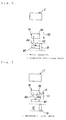
- FIG. 15 and Fig. 16 (a plan view), it is preferable that stoppers for defining a position are respectively provided to an inspecting position C1 for the leaking liquid inspection and an inspecting position C2 for the entering air inspection.
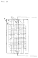
- the leaking liquid inspection apparatus is almost the same as apparatus disclosed by Japanese Patent Application Disclosure No. 5-124628, but as shown in Fig. 17, there is a different point by which plural slender members 72 as an insulator are designed on an electrode plate 70.
- the slender member 72 prevents the containers W, W1 from directly touching an electrode 74.
- the difference point is cited as difference in expression mainly but the technical contents are the same as the contents disclosed by Japanese Patent Application Disclosure No. 5-124628, so that repetitive explanation is omitted.
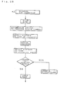
- Fig. 19 illustrates a flowchart of inspection carried out in the entering air inspection apparatus.
- the entering air inspection apparatus is the same as an apparatus disclosed by Japanese Patent Application Disclosure No. 5-124629 except the difference in expression, so that repetitive explanation is omitted.
Landscapes
- Physics & Mathematics (AREA)
- General Physics & Mathematics (AREA)
- Examining Or Testing Airtightness (AREA)
- Dairy Products (AREA)
- Application Of Or Painting With Fluid Materials (AREA)
- Road Signs Or Road Markings (AREA)
- Electrical Discharge Machining, Electrochemical Machining, And Combined Machining (AREA)
- Sampling And Sample Adjustment (AREA)
Applications Claiming Priority (3)
| Application Number | Priority Date | Filing Date | Title |
|---|---|---|---|
| JP219778/94 | 1994-09-14 | ||
| JP6219778A JP2780151B2 (ja) | 1994-09-14 | 1994-09-14 | 検査機構 |
| JP21977894 | 1994-09-14 |
Publications (3)
| Publication Number | Publication Date |
|---|---|
| EP0702223A2 true EP0702223A2 (de) | 1996-03-20 |
| EP0702223A3 EP0702223A3 (de) | 1998-04-22 |
| EP0702223B1 EP0702223B1 (de) | 2000-04-26 |
Family
ID=16740861
Family Applications (1)
| Application Number | Title | Priority Date | Filing Date |
|---|---|---|---|
| EP95306446A Expired - Lifetime EP0702223B1 (de) | 1994-09-14 | 1995-09-14 | Inspektionssystem |
Country Status (6)
| Country | Link |
|---|---|
| US (1) | US5618990A (de) |
| EP (1) | EP0702223B1 (de) |
| JP (1) | JP2780151B2 (de) |
| CA (1) | CA2157956A1 (de) |
| DE (1) | DE69516473T2 (de) |
| NO (1) | NO313216B1 (de) |
Cited By (1)
| Publication number | Priority date | Publication date | Assignee | Title |
|---|---|---|---|---|
| US7614282B2 (en) | 2004-06-07 | 2009-11-10 | Inspection Machinery (No 2) Pty Ltd. | Apparatus and method for testing flexible packages for defects |
Families Citing this family (6)
| Publication number | Priority date | Publication date | Assignee | Title |
|---|---|---|---|---|
| US6578407B1 (en) * | 2002-01-25 | 2003-06-17 | Valiant Corporation | System for leak testing industrial components |
| US7421886B1 (en) | 2007-06-15 | 2008-09-09 | Fox Michael A | Quick connect coupling test apparatus and method |
| WO2012129496A1 (en) * | 2011-03-23 | 2012-09-27 | Comau Inc. | Flexible leak test apparatus and method |
| KR102291054B1 (ko) | 2014-06-05 | 2021-08-20 | 가부시키가이샤 엔테크 | 용기 검사 장치 |
| CN113237604B (zh) * | 2021-06-28 | 2022-12-06 | 苏州大学 | 一种用于逆变器气密测试和通电测试的设备 |
| CN115026013B (zh) * | 2022-05-31 | 2023-12-19 | 博众精工科技股份有限公司 | 一种气密检测装置及检测流水线 |
Citations (1)
| Publication number | Priority date | Publication date | Assignee | Title |
|---|---|---|---|---|
| JPH05124628A (ja) | 1991-10-22 | 1993-05-21 | Yakult Honsha Co Ltd | 液漏れ検査装置 |
Family Cites Families (15)
| Publication number | Priority date | Publication date | Assignee | Title |
|---|---|---|---|---|
| CA646086A (en) * | 1962-08-07 | A. Thompson Earl | Gaging and sorting apparatus | |
| US3221539A (en) * | 1958-12-10 | 1965-12-07 | Ajem Lab Inc | Method and apparatus for leak testing castings |
| US3132508A (en) * | 1961-02-09 | 1964-05-12 | Gard Ind Inc | Pressure tester and rejecter |
| US3465572A (en) * | 1968-01-29 | 1969-09-09 | Aerojet General Co | Method and apparatus for simultaneous testing of containers for ability to withstand internal pressurization and for fluid leakage |
| AU449169B2 (en) * | 1968-10-23 | 1974-05-16 | Owens-Illinois, Inc | Leak detector |
| US4099404A (en) * | 1974-05-31 | 1978-07-11 | General Battery Corporation | Automatic air leak testing apparatus and method for batteries |
| JPS5235691A (en) * | 1975-09-16 | 1977-03-18 | Citizen Watch Co Ltd | Surface inspection apparatus for cylindrical pellets |
| JPS5317492A (en) * | 1976-07-29 | 1978-02-17 | Shiyouetsu Aono | Apparatus for automatically constant ouantity charging and transferring |
| US4081991A (en) * | 1976-08-09 | 1978-04-04 | Powers Manufacturing, Inc. | Apparatus for pressure testing frangible containers |
| US4602499A (en) * | 1984-12-24 | 1986-07-29 | Scans Associates, Inc. | Flexible industrial system with quick change part holding means |
| US4788850A (en) * | 1987-04-06 | 1988-12-06 | Five X Corporation | Bottle testing apparatus |
| AT393198B (de) * | 1989-03-13 | 1991-08-26 | Haas Franz Waffelmasch | Waffelteig, gebackenem backteig oder dergleichen |
| US5193685A (en) * | 1991-06-20 | 1993-03-16 | Trevithick William J | Gemstone sorting apparatus and methods |
| JPH085471B2 (ja) * | 1991-10-22 | 1996-01-24 | 株式会社ヤクルト本社 | エアー混入検査装置 |
| US5284252A (en) * | 1991-11-13 | 1994-02-08 | United Parcel Service Of America, Inc. | Automatic rotary sorter |
-
1994
- 1994-09-14 JP JP6219778A patent/JP2780151B2/ja not_active Expired - Fee Related
-
1995
- 1995-09-11 CA CA002157956A patent/CA2157956A1/en not_active Abandoned
- 1995-09-13 US US08/527,599 patent/US5618990A/en not_active Expired - Fee Related
- 1995-09-13 NO NO19953613A patent/NO313216B1/no not_active IP Right Cessation
- 1995-09-14 EP EP95306446A patent/EP0702223B1/de not_active Expired - Lifetime
- 1995-09-14 DE DE69516473T patent/DE69516473T2/de not_active Expired - Fee Related
Patent Citations (1)
| Publication number | Priority date | Publication date | Assignee | Title |
|---|---|---|---|---|
| JPH05124628A (ja) | 1991-10-22 | 1993-05-21 | Yakult Honsha Co Ltd | 液漏れ検査装置 |
Cited By (1)
| Publication number | Priority date | Publication date | Assignee | Title |
|---|---|---|---|---|
| US7614282B2 (en) | 2004-06-07 | 2009-11-10 | Inspection Machinery (No 2) Pty Ltd. | Apparatus and method for testing flexible packages for defects |
Also Published As
| Publication number | Publication date |
|---|---|
| EP0702223A3 (de) | 1998-04-22 |
| DE69516473D1 (de) | 2000-05-31 |
| JP2780151B2 (ja) | 1998-07-30 |
| EP0702223B1 (de) | 2000-04-26 |
| NO953613D0 (no) | 1995-09-13 |
| US5618990A (en) | 1997-04-08 |
| DE69516473T2 (de) | 2000-09-07 |
| JPH0880918A (ja) | 1996-03-26 |
| NO313216B1 (no) | 2002-08-26 |
| NO953613L (no) | 1996-03-15 |
| CA2157956A1 (en) | 1996-03-15 |
Similar Documents
| Publication | Publication Date | Title |
|---|---|---|
| EP0702223B1 (de) | Inspektionssystem | |
| EP0242567A1 (de) | Vorrichtung zum Füllen von Beuteln | |
| JP7140823B2 (ja) | ピンホール検査装置及びピンホールの有無が検査された包装袋の製造方法 | |
| CN211013425U (zh) | 一种液态生料带瓶的密封性检测装置 | |
| WO2016088713A1 (ja) | チューブ容器検査装置 | |
| JP5760520B2 (ja) | リーク検査装置 | |
| CN114007942A (zh) | 一种出厂检查装置、具有该装置的包装装置及包装系统 | |
| JP2000046685A (ja) | 包装袋体内空気の漏洩検出方法並びに装置 | |
| US20180297792A1 (en) | Transport module for transporting a container and a processing device and a method for transporting a container | |
| CN115415184A (zh) | 直线连续式塑料安瓿真空衰减检漏机 | |
| CN210349983U (zh) | 预处理装置 | |
| CN220195619U (zh) | 密封检测生产线 | |
| US11524850B2 (en) | Treatment device and container treatment machine | |
| JP2002029628A (ja) | パウチ搬送装置 | |
| CN113666324B (zh) | 软桶新鲜矿泉水灌装装置、工艺以及托瓶设备 | |
| CN213700832U (zh) | 一种药袋在线翻面输送装置 | |
| CN210047716U (zh) | 排气装置及具有其的封口设备 | |
| JP2002162365A (ja) | 密封包装袋のピンホール検出方法及びその装置 | |
| JP2002154505A (ja) | 容器包装装置 | |
| JP2005298024A (ja) | 液体の充填方法及び装置 | |
| CN222248931U (zh) | 一种用于塑料瓶加工的输送定位装置 | |
| WO2018228244A1 (zh) | 全自动智能衣服包装系统 | |
| CN218751733U (zh) | 一种面膜灌装设备 | |
| CN221832846U (zh) | 一种五金件平面度检测装置 | |
| CN215974930U (zh) | 软桶新鲜矿泉水灌装装置以及托瓶设备 |
Legal Events
| Date | Code | Title | Description |
|---|---|---|---|
| PUAI | Public reference made under article 153(3) epc to a published international application that has entered the european phase |
Free format text: ORIGINAL CODE: 0009012 |
|
| AK | Designated contracting states |
Kind code of ref document: A2 Designated state(s): CH DE FR GB IT LI NL SE |
|
| PUAL | Search report despatched |
Free format text: ORIGINAL CODE: 0009013 |
|
| AK | Designated contracting states |
Kind code of ref document: A3 Designated state(s): CH DE FR GB IT LI NL SE |
|
| 17P | Request for examination filed |
Effective date: 19980604 |
|
| GRAG | Despatch of communication of intention to grant |
Free format text: ORIGINAL CODE: EPIDOS AGRA |
|
| 17Q | First examination report despatched |
Effective date: 19990820 |
|
| GRAG | Despatch of communication of intention to grant |
Free format text: ORIGINAL CODE: EPIDOS AGRA |
|
| GRAH | Despatch of communication of intention to grant a patent |
Free format text: ORIGINAL CODE: EPIDOS IGRA |
|
| GRAH | Despatch of communication of intention to grant a patent |
Free format text: ORIGINAL CODE: EPIDOS IGRA |
|
| GRAA | (expected) grant |
Free format text: ORIGINAL CODE: 0009210 |
|
| AK | Designated contracting states |
Kind code of ref document: B1 Designated state(s): CH DE FR GB IT LI NL SE |
|
| REG | Reference to a national code |
Ref country code: CH Ref legal event code: NV Representative=s name: A. BRAUN, BRAUN, HERITIER, ESCHMANN AG PATENTANWAE Ref country code: CH Ref legal event code: EP |
|
| ITF | It: translation for a ep patent filed | ||
| REF | Corresponds to: |
Ref document number: 69516473 Country of ref document: DE Date of ref document: 20000531 |
|
| ET | Fr: translation filed | ||
| PLBE | No opposition filed within time limit |
Free format text: ORIGINAL CODE: 0009261 |
|
| STAA | Information on the status of an ep patent application or granted ep patent |
Free format text: STATUS: NO OPPOSITION FILED WITHIN TIME LIMIT |
|
| 26N | No opposition filed | ||
| REG | Reference to a national code |
Ref country code: GB Ref legal event code: IF02 |
|
| PGFP | Annual fee paid to national office [announced via postgrant information from national office to epo] |
Ref country code: SE Payment date: 20030904 Year of fee payment: 9 |
|
| PGFP | Annual fee paid to national office [announced via postgrant information from national office to epo] |
Ref country code: FR Payment date: 20030909 Year of fee payment: 9 |
|
| PGFP | Annual fee paid to national office [announced via postgrant information from national office to epo] |
Ref country code: GB Payment date: 20030910 Year of fee payment: 9 |
|
| PGFP | Annual fee paid to national office [announced via postgrant information from national office to epo] |
Ref country code: CH Payment date: 20030918 Year of fee payment: 9 |
|
| PGFP | Annual fee paid to national office [announced via postgrant information from national office to epo] |
Ref country code: NL Payment date: 20030922 Year of fee payment: 9 |
|
| PGFP | Annual fee paid to national office [announced via postgrant information from national office to epo] |
Ref country code: DE Payment date: 20030925 Year of fee payment: 9 |
|
| PG25 | Lapsed in a contracting state [announced via postgrant information from national office to epo] |
Ref country code: GB Free format text: LAPSE BECAUSE OF NON-PAYMENT OF DUE FEES Effective date: 20040914 |
|
| PG25 | Lapsed in a contracting state [announced via postgrant information from national office to epo] |
Ref country code: SE Free format text: LAPSE BECAUSE OF NON-PAYMENT OF DUE FEES Effective date: 20040915 |
|
| PG25 | Lapsed in a contracting state [announced via postgrant information from national office to epo] |
Ref country code: LI Free format text: LAPSE BECAUSE OF NON-PAYMENT OF DUE FEES Effective date: 20040930 Ref country code: CH Free format text: LAPSE BECAUSE OF NON-PAYMENT OF DUE FEES Effective date: 20040930 |
|
| PG25 | Lapsed in a contracting state [announced via postgrant information from national office to epo] |
Ref country code: NL Free format text: LAPSE BECAUSE OF NON-PAYMENT OF DUE FEES Effective date: 20050401 Ref country code: DE Free format text: LAPSE BECAUSE OF NON-PAYMENT OF DUE FEES Effective date: 20050401 |
|
| EUG | Se: european patent has lapsed | ||
| GBPC | Gb: european patent ceased through non-payment of renewal fee |
Effective date: 20040914 |
|
| REG | Reference to a national code |
Ref country code: CH Ref legal event code: PL |
|
| PG25 | Lapsed in a contracting state [announced via postgrant information from national office to epo] |
Ref country code: FR Free format text: LAPSE BECAUSE OF NON-PAYMENT OF DUE FEES Effective date: 20050531 |
|
| NLV4 | Nl: lapsed or anulled due to non-payment of the annual fee |
Effective date: 20050401 |
|
| REG | Reference to a national code |
Ref country code: FR Ref legal event code: ST |
|
| PG25 | Lapsed in a contracting state [announced via postgrant information from national office to epo] |
Ref country code: IT Free format text: LAPSE BECAUSE OF NON-PAYMENT OF DUE FEES Effective date: 20050914 |