EP0702246A1 - Tragbares Gerät zum Messen der Rückstreuung von Licht - Google Patents
Tragbares Gerät zum Messen der Rückstreuung von Licht Download PDFInfo
- Publication number
- EP0702246A1 EP0702246A1 EP95402062A EP95402062A EP0702246A1 EP 0702246 A1 EP0702246 A1 EP 0702246A1 EP 95402062 A EP95402062 A EP 95402062A EP 95402062 A EP95402062 A EP 95402062A EP 0702246 A1 EP0702246 A1 EP 0702246A1
- Authority
- EP
- European Patent Office
- Prior art keywords
- mirror
- input
- reflectors
- diameter
- telescope
- Prior art date
- Legal status (The legal status is an assumption and is not a legal conclusion. Google has not performed a legal analysis and makes no representation as to the accuracy of the status listed.)
- Granted
Links
- 230000003287 optical effect Effects 0.000 claims abstract description 21
- 230000004907 flux Effects 0.000 claims description 2
- 230000004075 alteration Effects 0.000 description 6
- 241000581464 Dactyloscopidae Species 0.000 description 5
- 239000000443 aerosol Substances 0.000 description 3
- 238000005259 measurement Methods 0.000 description 3
- 238000010276 construction Methods 0.000 description 2
- 238000001514 detection method Methods 0.000 description 2
- 238000010586 diagram Methods 0.000 description 2
- 229910052732 germanium Inorganic materials 0.000 description 2
- GNPVGFCGXDBREM-UHFFFAOYSA-N germanium atom Chemical compound [Ge] GNPVGFCGXDBREM-UHFFFAOYSA-N 0.000 description 2
- 238000000429 assembly Methods 0.000 description 1
- 230000008901 benefit Effects 0.000 description 1
- 230000005540 biological transmission Effects 0.000 description 1
- 230000001427 coherent effect Effects 0.000 description 1
- 230000007547 defect Effects 0.000 description 1
- 229910003460 diamond Inorganic materials 0.000 description 1
- 239000010432 diamond Substances 0.000 description 1
- 230000000694 effects Effects 0.000 description 1
- 229940082150 encore Drugs 0.000 description 1
- 235000021183 entrée Nutrition 0.000 description 1
- 210000000887 face Anatomy 0.000 description 1
- 238000003754 machining Methods 0.000 description 1
- 230000007246 mechanism Effects 0.000 description 1
- 239000000203 mixture Substances 0.000 description 1
- 230000003071 parasitic effect Effects 0.000 description 1
- 239000002245 particle Substances 0.000 description 1
- 210000001747 pupil Anatomy 0.000 description 1
- 230000009467 reduction Effects 0.000 description 1
- 239000000523 sample Substances 0.000 description 1
- 238000010408 sweeping Methods 0.000 description 1
Images

Classifications
-
- G—PHYSICS
- G01—MEASURING; TESTING
- G01S—RADIO DIRECTION-FINDING; RADIO NAVIGATION; DETERMINING DISTANCE OR VELOCITY BY USE OF RADIO WAVES; LOCATING OR PRESENCE-DETECTING BY USE OF THE REFLECTION OR RERADIATION OF RADIO WAVES; ANALOGOUS ARRANGEMENTS USING OTHER WAVES
- G01S7/00—Details of systems according to groups G01S13/00, G01S15/00, G01S17/00
- G01S7/48—Details of systems according to groups G01S13/00, G01S15/00, G01S17/00 of systems according to group G01S17/00
- G01S7/481—Constructional features, e.g. arrangements of optical elements
- G01S7/4817—Constructional features, e.g. arrangements of optical elements relating to scanning
-
- G—PHYSICS
- G02—OPTICS
- G02B—OPTICAL ELEMENTS, SYSTEMS OR APPARATUS
- G02B26/00—Optical devices or arrangements for the control of light using movable or deformable optical elements
- G02B26/08—Optical devices or arrangements for the control of light using movable or deformable optical elements for controlling the direction of light
- G02B26/10—Scanning systems
Definitions
- the present invention relates to devices on board an air or space vehicle, intended for measuring the backscattering of light by a distant scene.
- lidars comprising a laser for emitting short light pulses, a channel for receiving the backscattered light flux and conical scanning optical means making it possible to orient a common direction of emission of the laser and reception by said channel according to successive generators of a cone.
- the invention finds an important application in the field of lidars on board satellites and intended for meteorological exploration of the earth.
- These lidars emit a laser pulse, from a few nanoseconds to a few microseconds in length, through a telescope.
- the wave backscattered by aerosol particles from the atmosphere can measure parameters such as aerosol concentration or wind speed.
- a cutting of the return signal by time windows makes it possible to draw up a map of the parameters across the thickness of the atmosphere probed.
- the lidars used can be inconsistent: they then only provide information on the variation of the aerosol density as a function of the altitude and on the altitude of the tops of the clouds, unless the Doppler shift is detected by a spectrometer such as 'a Fabry-Pérot.
- Doppler lidars which allow direct measurement of wind speed by Doppler effect and heterodyne detection, the backscattered wave undergoing a proportional frequency shift at the relative radial speed of the target.
- the wind speed at a given altitude is then obtained by subtracting, from the measured relative radial speed, the contributions from the speed of the carrier of the device and from the drive speed linked to the rotation of the earth.
- a device of the above type intended for meteorological applications is therefore advantageously provided for measuring at least two components of the speed, separated by approximately 30 °.
- the line of sight of a transmitting telescope fixed with respect to the satellite describes a curve on the surface of the earth which reproduces the track of the satellite.
- the device To obtain good coverage of the earth, it is necessary for the device to probe the atmosphere on either side of the trace of the satellite on the ground.
- a scanning device located in front of it such as a plane mirror, giving a conical scan, which results in a line cycloid sweep on the ground.
- the invention aims in particular to provide a device of the type defined above, which meets the requirements of practice better than those previously known. It aims in particular to reduce the mass and dimensions of the moving parts necessary to carry out the conical scanning.
- the invention proposes in particular a device of the kind defined above, in accordance with claim 1.
- the reflectors can in particular be constituted by fractions outside the paraboloid axis which each focus a parallel beam of light coming from the scene observed towards the rotating mirror. These paraboloid fractions thus constitute both reflectors and successive telescope components.
- the reflectors are arranged between a lens reduction optic for the diameter of the input and output beam of the device and said rotary mirror.
- This lens optic can comprise a single telescope proper and, for each of the successive viewing directions, a corrective optical element which can also be provided to give rise to a parallel beam of light, directed parallel to the axis of rotation of the mirror. rotary, of much smaller diameter than the diameter of the input and output beam of the device.
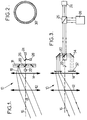
- the device comprises a telescope 10, dioptric in the case of FIG. 1, constituted by an input lens 12 and a field lens 14. These lenses are calculated so that an incident parallel beam in a direction of angle of incidence ⁇ relative to the axis 16 of the telescope (this axis 16 being oriented towards the nadir when used on satellite) gives rise to a beam converging on a focal plane 18, of axis 19 parallel to the optical axis of the telescope 16 which constitutes the scanning axis.
- Optical scanning means comprise a mirror 20 placed on the axis 16, having a dimension much smaller than that of the input beam collected by the lens 12.
- a stepping motor 22 makes it possible to rotate the mirror 20 around axis 16.
- a deflection mirror 25 corresponds to each possible position of the mirror 20.
- the mirror 20 Due to the low inertia of the mirror 20, it is possible to make it advance step by step, keeping it in the same position during transmission and until complete reception of the return echo. This eliminates the angular aberrations that would cause a scan at constant angular speed.
- the translational movement of the satellite does not in fact induce angular aberrations, due to the composition of the speeds.
- the step-by-step operating mode eliminates microvibrations from a continuous scanning mechanism.
- FIG. 3 shows a possible constitution of the device, the principle diagram of which is given in FIG. 1.
- Each angular stop position of the mirror 20 corresponds to an optical sub-assembly comprising a diverging lens 32 providing an output beam parallel to the axis 16 and a mirror 34 returning to the rotating mirror 20.
- the lens 32 can be aspherical and constitute a corrective element. It can also be replaced or supplemented by a corrective element such as a blade with aspherical parallel faces or a holographic element.
- the separator 26 may be constituted by an electro-optical switch.
- the inlet opening diameter of such a device is only limited by the diameter which it is possible to give to the lenses 12 and 14. In the case of a device intended to operate in the infrared, comprising so germanium lenses, it is difficult to exceed a diameter of 50 cm.
- the telescope makes it possible to reduce the diameter of the input beam by a factor of around 10, within an acceptable size.
- the telescope can have the constitution shown in figure 4, with germanium lenses.
- the single lens 14 of FIG. 2 is replaced by two lenses with spherical surfaces 14a and 14b.
- the corrective element shown in FIG. 4 comprises a divergent lens 32 giving rise to a parallel beam and an aspherical blade 33 which serves to compensate for the residual aberrations.
- the speed measurement will generally be carried out by heterodyne detection on the signal supplied by the detector 24.
- a lens telescope like the one in Figure 3 does not allow to go beyond a scanning angle ⁇ of about 45 ° and an input diameter of about 50 cm, in infrared .
- a telescope with angularly distributed mirrors When looking for large scanning angles and / or entry diameters, you can use a telescope with angularly distributed mirrors.
- Figure 5 shows the basic construction of such a device.
- the telescope comprises several fractions, each materialized by a parabolic or pseudo-parabolic mirror 36, off axis.
- the number of fractions corresponds to the number of successive positions given to the scanning mirror 20 (usually from 4 to 20).
- the successive directions of emission and reception are all located on a cone whose apex angle is defined by the characteristics of the parabolic mirrors 36.
- a corrective element 32 is further interposed on each optical path, between the rotating mirror 20 and the respective parabolic mirror 36.
- the device shown in Figure 5, like that of Figure 3, allows without difficulty to reduce the diameter of the input-output beam in a ratio of about 10. It has the advantage of authorizing the obtaining of a sweeping cone with a half-angle at the top ⁇ high, which can easily exceed 45 °. In addition, the diameter of the beam emitted or received can easily exceed one meter.
- FIGS. 6 and 7 show a system comprising several devices 38 (three for example) which may have one of the constitutions described above, if not that they include a laser 28 and a common detector.
- the three devices have different orientations, so that the traces on the ground of the beam, assuming the fixed satellite, have an offset relative arrangement, like that shown in FIG. 7.
- the devices 38 are used successively by orienting the beams coming from their mirrors output turns 20 towards the switch 26, by means of an additional respective return mirror 40 and of a mirror rotating in some positions 42 controlled by a stepping motor 44.
- the reception beam has a width at least equivalent to a circle of 0.5 m in diameter.
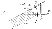
- the embodiment shown in Figure 8 achieves this result with limited space, reduced mass and relatively easy to perform elements.
- each aspherical mirror 46 - lens 50 assembly receives a beam comprised between the generator 48 of the scanning cone 8 and the beam 52.
- the mirror 36 is scalloped on each optical path to bypass the passage of light.
- the primary mirror 36 being spherical, its realization is easy. It can have a large aperture on the order of F / 0.5, which reduces the size of the telescope.
- the mirror 46 and the lens 50 are of revolution, so that they can be produced without difficulty by diamond machining.
- the aspherization of the system 46 - 50 is calculated so as to obtain a stigmatic system for the direction and to satisfy the condition of aplanetism around the direction 48.
- the lidar operates in step-by-step mode and that the optical parts are fixed during emission and reception of the laser pulse, the required field is practically zero.
- the existence of a nonzero field where the telescope is limited by diffraction, is useful on the one hand for the alignment of the telescope on the ground and on the other hand to take into account the defects of optical alignments in flight.
- a device actually produced comprises a mirror 36 1.4 m in diameter and eight to twelve sets 46 - 50 - 25 regularly distributed around the axis 16. Each set corresponds to a generator 48 and to an angular position of the scanning mirror 20.
Landscapes
- Physics & Mathematics (AREA)
- General Physics & Mathematics (AREA)
- Engineering & Computer Science (AREA)
- Optics & Photonics (AREA)
- Computer Networks & Wireless Communication (AREA)
- Radar, Positioning & Navigation (AREA)
- Remote Sensing (AREA)
- Optical Radar Systems And Details Thereof (AREA)
- Photometry And Measurement Of Optical Pulse Characteristics (AREA)
Applications Claiming Priority (2)
| Application Number | Priority Date | Filing Date | Title |
|---|---|---|---|
| FR9410905 | 1994-09-13 | ||
| FR9410905A FR2724464B1 (fr) | 1994-09-13 | 1994-09-13 | Dispositif embarquable de mesure de retrodiffusion de lumiere |
Publications (2)
| Publication Number | Publication Date |
|---|---|
| EP0702246A1 true EP0702246A1 (de) | 1996-03-20 |
| EP0702246B1 EP0702246B1 (de) | 1997-11-19 |
Family
ID=9466890
Family Applications (1)
| Application Number | Title | Priority Date | Filing Date |
|---|---|---|---|
| EP95402062A Expired - Lifetime EP0702246B1 (de) | 1994-09-13 | 1995-09-12 | Tragbares Gerät zum Messen der Rückstreuung von Licht |
Country Status (6)
| Country | Link |
|---|---|
| US (1) | US5598263A (de) |
| EP (1) | EP0702246B1 (de) |
| JP (1) | JPH08178749A (de) |
| DE (1) | DE69501072T2 (de) |
| ES (1) | ES2110303T3 (de) |
| FR (1) | FR2724464B1 (de) |
Cited By (1)
| Publication number | Priority date | Publication date | Assignee | Title |
|---|---|---|---|---|
| EP3026475A1 (de) * | 2014-11-25 | 2016-06-01 | NCR Corporation | Abtaster mit einstellbarem sichtfeld |
Families Citing this family (10)
| Publication number | Priority date | Publication date | Assignee | Title |
|---|---|---|---|---|
| FR2766931B1 (fr) * | 1997-08-01 | 1999-10-15 | Sextant Avionique | Dispositif optique pour viseur de casque comportant un miroir aspherique |
| FR2833086B1 (fr) * | 2001-11-30 | 2004-02-27 | Thales Sa | Dispositif de veille optronique sectorielle ou panoramique a grande vitesse sans mouvement apparent |
| IT1391180B1 (it) * | 2008-07-07 | 2011-11-18 | Consiglio Nazionale Ricerche | Procedimento per la caratterizzazione del particolato atmosferico mediante un dispositivo lidar a retrodiffusione elastica e retroriflessione, e sistema lidar per l'attuazione del procedimento |
| US7920262B2 (en) * | 2008-09-17 | 2011-04-05 | The United States Of America As Represented By The Secretary Of The Army | Systems for measuring backscattered light using rotating mirror |
| US8169596B2 (en) | 2009-08-17 | 2012-05-01 | Seegrid Corporation | System and method using a multi-plane curtain |
| EP3220160B9 (de) * | 2016-03-14 | 2020-03-04 | Riegl Laser Measurement Systems GmbH | Fluggerät mit laserscanner |
| US11474254B2 (en) | 2017-11-07 | 2022-10-18 | Piaggio Fast Forward Inc. | Multi-axes scanning system from single-axis scanner |
| DE102018125826A1 (de) | 2018-10-18 | 2020-04-23 | Sick Ag | Optoelektronischer Sensor und Verfahren zur Erfassung von Objekten |
| DE102020102247A1 (de) * | 2020-01-30 | 2021-08-05 | Sick Ag | Optoelektronischer Sensor und Verfahren zur Erfassung von Objekten |
| US20230393245A1 (en) * | 2020-10-23 | 2023-12-07 | Sense Photonics, Inc. | Integrated long-range narrow-fov and short-range wide-fov solid-state flash lidar system |
Citations (4)
| Publication number | Priority date | Publication date | Assignee | Title |
|---|---|---|---|---|
| US4340299A (en) * | 1980-03-13 | 1982-07-20 | United Technologies Corporation | Optical doppler radar system using a conically scanned laser beam |
| DE9010222U1 (de) * | 1990-07-05 | 1991-08-01 | Birkle, Gebhard, 7750 Konstanz | Ringförmiger Spiegel- oder Brechungskörper, vorzugsweise zum optischen Abtasten der Oberfläche eines Objektes, dessen Oberfläche Licht zu reflektieren, zu streuen oder zu brechen imstande ist |
| US5071239A (en) | 1989-02-23 | 1991-12-10 | United Technologies Corporation | Catadioptric conically scanning telescope |
| US5255065A (en) * | 1992-03-10 | 1993-10-19 | The United States Of America As Represented By The Administrator Of The National Aeronautics And Space Administration | Conically scanned holographic lidar telescope |
Family Cites Families (3)
| Publication number | Priority date | Publication date | Assignee | Title |
|---|---|---|---|---|
| US4328421A (en) * | 1980-02-25 | 1982-05-04 | Barnes Engineering Company | Horizon sensor |
| US4459024A (en) * | 1981-12-09 | 1984-07-10 | Conoco Inc. | Method and apparatus for light detection and ranging for use in visually obstructed areas |
| US5418608A (en) * | 1993-05-04 | 1995-05-23 | Harbor Branch Oceanographic Institution Inc. | Three dimensional mapping systems and methods |
-
1994
- 1994-09-13 FR FR9410905A patent/FR2724464B1/fr not_active Expired - Lifetime
-
1995
- 1995-09-12 US US08/526,932 patent/US5598263A/en not_active Expired - Lifetime
- 1995-09-12 ES ES95402062T patent/ES2110303T3/es not_active Expired - Lifetime
- 1995-09-12 DE DE69501072T patent/DE69501072T2/de not_active Expired - Lifetime
- 1995-09-12 EP EP95402062A patent/EP0702246B1/de not_active Expired - Lifetime
- 1995-09-13 JP JP7235642A patent/JPH08178749A/ja not_active Withdrawn
Patent Citations (4)
| Publication number | Priority date | Publication date | Assignee | Title |
|---|---|---|---|---|
| US4340299A (en) * | 1980-03-13 | 1982-07-20 | United Technologies Corporation | Optical doppler radar system using a conically scanned laser beam |
| US5071239A (en) | 1989-02-23 | 1991-12-10 | United Technologies Corporation | Catadioptric conically scanning telescope |
| DE9010222U1 (de) * | 1990-07-05 | 1991-08-01 | Birkle, Gebhard, 7750 Konstanz | Ringförmiger Spiegel- oder Brechungskörper, vorzugsweise zum optischen Abtasten der Oberfläche eines Objektes, dessen Oberfläche Licht zu reflektieren, zu streuen oder zu brechen imstande ist |
| US5255065A (en) * | 1992-03-10 | 1993-10-19 | The United States Of America As Represented By The Administrator Of The National Aeronautics And Space Administration | Conically scanned holographic lidar telescope |
Cited By (1)
| Publication number | Priority date | Publication date | Assignee | Title |
|---|---|---|---|---|
| EP3026475A1 (de) * | 2014-11-25 | 2016-06-01 | NCR Corporation | Abtaster mit einstellbarem sichtfeld |
Also Published As
| Publication number | Publication date |
|---|---|
| ES2110303T3 (es) | 1998-02-01 |
| EP0702246B1 (de) | 1997-11-19 |
| DE69501072D1 (de) | 1998-01-02 |
| DE69501072T2 (de) | 1998-06-18 |
| FR2724464B1 (fr) | 1996-11-22 |
| US5598263A (en) | 1997-01-28 |
| FR2724464A1 (fr) | 1996-03-15 |
| JPH08178749A (ja) | 1996-07-12 |
Similar Documents
| Publication | Publication Date | Title |
|---|---|---|
| EP0004227B1 (de) | Einrichtung zur optoelektrischen Detektion und zur Bestimmung der Winkelablage eines leuchtenden Objekts, sowie deren Verwendung | |
| EP0419320B1 (de) | Vorrichtung zur automatischen Harmonisierung für ein opto-elektronisches System | |
| EP2173042B1 (de) | Optische Sende-Empfangseinheit mit Kontrolle der Senderichtung | |
| FR2539864A1 (fr) | Systeme de guidage d'engin par faisceau lumineux | |
| EP0702246B1 (de) | Tragbares Gerät zum Messen der Rückstreuung von Licht | |
| EP1449020B1 (de) | Einrichtung zur schnellen sektoriellen oder panoramischen überwachung ohne anscheinende bewegung | |
| EP0034772B1 (de) | Vorrichtung zur Bestimmung der Winkellage eines mittels Lichtpulse beleuchteten Zieles | |
| FR2690997A1 (fr) | Système optoélectronique d'acquisition de cible à très grand champ. | |
| FR2686312A1 (fr) | Vehicule spatial d'observation laser, notamment pour vitesse de vents, et instrument d'observation adapte a en faire partie. | |
| EP0241374A1 (de) | Optronische Abweichungsvorrichtung zur räumlichen und spektralen Erkennung von infraroten Lichtquellen | |
| FR2505505A1 (fr) | Dispositif laser pour detecter et neutraliser l'optique d'un appareil de reperage adverse | |
| EP0778958B1 (de) | Vorrichtung zum ausrichten eines beobachtungsinstrumentes | |
| EP0189217A1 (de) | Optisch-mechanischer Analysator mit einem festen telemetrischen Feld | |
| EP0353138A1 (de) | Multispektrales Spiegelgerät | |
| EP0645020A1 (de) | Rundumsichtgerät mit optimaler raumabdeckung durch aneinanderfügen von sichtfeldern | |
| FR2687791A1 (fr) | Systeme optronique de poursuite tridimensionnelle avec alignement automatique d'un telemetre optique sur la cible. | |
| EP3607352B1 (de) | Vorrichtung zur datenerfassung auf einem ziel, plattform und verfahren dafür | |
| EP1856552B1 (de) | Gegenmassnahmevorrichtung zur bedrohungsverfolgung in form eines zielsuchkopfflugkörper | |
| FR2690532A1 (fr) | Dispositif de pointage pour appareil optique. | |
| FR2576115A1 (fr) | Analyseur optico-mecanique ayant un champ de telemetrie fixe | |
| EP0684488A1 (de) | Laser-Beobachtungsanordnung in Weltraum, und Raumfahrzeug damit | |
| FR2525339A1 (fr) | Dispositif laser pour guider un missile sur une cible | |
| FR2654218A1 (fr) | Systeme optronique de poursuite tridimensionnelle avec alignement automatique d'un telemetre optique sur la cible. | |
| EP0561680A1 (de) | Vorrichtung zum Messen der axialen Geschwindigkeit | |
| EP4544287A1 (de) | System zur bestimmung der dämpfung einer lichtwelle, die durch ein abtastvolumen fliesst |
Legal Events
| Date | Code | Title | Description |
|---|---|---|---|
| PUAI | Public reference made under article 153(3) epc to a published international application that has entered the european phase |
Free format text: ORIGINAL CODE: 0009012 |
|
| AK | Designated contracting states |
Kind code of ref document: A1 Designated state(s): BE DE ES GB IT NL |
|
| 17P | Request for examination filed |
Effective date: 19960409 |
|
| GRAG | Despatch of communication of intention to grant |
Free format text: ORIGINAL CODE: EPIDOS AGRA |
|
| 17Q | First examination report despatched |
Effective date: 19970321 |
|
| GRAH | Despatch of communication of intention to grant a patent |
Free format text: ORIGINAL CODE: EPIDOS IGRA |
|
| GRAH | Despatch of communication of intention to grant a patent |
Free format text: ORIGINAL CODE: EPIDOS IGRA |
|
| GRAA | (expected) grant |
Free format text: ORIGINAL CODE: 0009210 |
|
| AK | Designated contracting states |
Kind code of ref document: B1 Designated state(s): BE DE ES GB IT NL |
|
| GBT | Gb: translation of ep patent filed (gb section 77(6)(a)/1977) |
Effective date: 19971117 |
|
| ITF | It: translation for a ep patent filed | ||
| REF | Corresponds to: |
Ref document number: 69501072 Country of ref document: DE Date of ref document: 19980102 |
|
| REG | Reference to a national code |
Ref country code: ES Ref legal event code: FG2A Ref document number: 2110303 Country of ref document: ES Kind code of ref document: T3 |
|
| PLBE | No opposition filed within time limit |
Free format text: ORIGINAL CODE: 0009261 |
|
| STAA | Information on the status of an ep patent application or granted ep patent |
Free format text: STATUS: NO OPPOSITION FILED WITHIN TIME LIMIT |
|
| 26N | No opposition filed | ||
| REG | Reference to a national code |
Ref country code: GB Ref legal event code: IF02 |
|
| PGFP | Annual fee paid to national office [announced via postgrant information from national office to epo] |
Ref country code: NL Payment date: 20020815 Year of fee payment: 8 |
|
| PGFP | Annual fee paid to national office [announced via postgrant information from national office to epo] |
Ref country code: ES Payment date: 20020826 Year of fee payment: 8 |
|
| PGFP | Annual fee paid to national office [announced via postgrant information from national office to epo] |
Ref country code: BE Payment date: 20021011 Year of fee payment: 8 |
|
| PG25 | Lapsed in a contracting state [announced via postgrant information from national office to epo] |
Ref country code: ES Free format text: LAPSE BECAUSE OF NON-PAYMENT OF DUE FEES Effective date: 20030913 |
|
| PG25 | Lapsed in a contracting state [announced via postgrant information from national office to epo] |
Ref country code: BE Free format text: LAPSE BECAUSE OF NON-PAYMENT OF DUE FEES Effective date: 20030930 |
|
| BERE | Be: lapsed |
Owner name: *MATRA MARCONI SPACE FRANCE Effective date: 20030930 |
|
| PG25 | Lapsed in a contracting state [announced via postgrant information from national office to epo] |
Ref country code: NL Free format text: LAPSE BECAUSE OF NON-PAYMENT OF DUE FEES Effective date: 20040401 |
|
| NLV4 | Nl: lapsed or anulled due to non-payment of the annual fee |
Effective date: 20040401 |
|
| REG | Reference to a national code |
Ref country code: ES Ref legal event code: FD2A Effective date: 20030913 |
|
| PGFP | Annual fee paid to national office [announced via postgrant information from national office to epo] |
Ref country code: DE Payment date: 20100910 Year of fee payment: 16 |
|
| PGFP | Annual fee paid to national office [announced via postgrant information from national office to epo] |
Ref country code: GB Payment date: 20110824 Year of fee payment: 17 |
|
| PGFP | Annual fee paid to national office [announced via postgrant information from national office to epo] |
Ref country code: IT Payment date: 20110926 Year of fee payment: 17 |
|
| GBPC | Gb: european patent ceased through non-payment of renewal fee |
Effective date: 20120912 |
|
| PG25 | Lapsed in a contracting state [announced via postgrant information from national office to epo] |
Ref country code: DE Free format text: LAPSE BECAUSE OF NON-PAYMENT OF DUE FEES Effective date: 20130403 Ref country code: GB Free format text: LAPSE BECAUSE OF NON-PAYMENT OF DUE FEES Effective date: 20120912 |
|
| PG25 | Lapsed in a contracting state [announced via postgrant information from national office to epo] |
Ref country code: IT Free format text: LAPSE BECAUSE OF NON-PAYMENT OF DUE FEES Effective date: 20120912 |
|
| REG | Reference to a national code |
Ref country code: DE Ref legal event code: R119 Ref document number: 69501072 Country of ref document: DE Effective date: 20130403 |