EP0702262A1 - Selbständiges Gerät zum Belichten und Entwickeln eines Filmes - Google Patents
Selbständiges Gerät zum Belichten und Entwickeln eines Filmes Download PDFInfo
- Publication number
- EP0702262A1 EP0702262A1 EP95306398A EP95306398A EP0702262A1 EP 0702262 A1 EP0702262 A1 EP 0702262A1 EP 95306398 A EP95306398 A EP 95306398A EP 95306398 A EP95306398 A EP 95306398A EP 0702262 A1 EP0702262 A1 EP 0702262A1
- Authority
- EP
- European Patent Office
- Prior art keywords
- film
- vacuum
- carriage
- frame
- machine
- Prior art date
- Legal status (The legal status is an assumption and is not a legal conclusion. Google has not performed a legal analysis and makes no representation as to the accuracy of the status listed.)
- Withdrawn
Links
- 238000011161 development Methods 0.000 claims abstract description 10
- 238000010438 heat treatment Methods 0.000 claims description 33
- 238000007600 charging Methods 0.000 claims description 15
- 238000007786 electrostatic charging Methods 0.000 claims description 6
- 238000002508 contact lithography Methods 0.000 claims description 4
- 230000004888 barrier function Effects 0.000 claims description 3
- 230000000903 blocking effect Effects 0.000 claims description 3
- 239000011324 bead Substances 0.000 claims description 2
- 230000007423 decrease Effects 0.000 claims description 2
- 230000002093 peripheral effect Effects 0.000 claims description 2
- 238000007789 sealing Methods 0.000 claims description 2
- 238000012545 processing Methods 0.000 abstract description 9
- 230000007246 mechanism Effects 0.000 abstract 1
- 239000011521 glass Substances 0.000 description 16
- 230000004913 activation Effects 0.000 description 10
- 239000000839 emulsion Substances 0.000 description 10
- 238000007639 printing Methods 0.000 description 4
- 230000009849 deactivation Effects 0.000 description 3
- 229920001821 foam rubber Polymers 0.000 description 3
- 238000000034 method Methods 0.000 description 3
- 230000008569 process Effects 0.000 description 3
- 238000005096 rolling process Methods 0.000 description 3
- 239000000126 substance Substances 0.000 description 3
- 230000008859 change Effects 0.000 description 2
- 238000011017 operating method Methods 0.000 description 2
- 230000000717 retained effect Effects 0.000 description 2
- RYGMFSIKBFXOCR-UHFFFAOYSA-N Copper Chemical compound [Cu] RYGMFSIKBFXOCR-UHFFFAOYSA-N 0.000 description 1
- NIXOWILDQLNWCW-UHFFFAOYSA-N acrylic acid group Chemical group C(C=C)(=O)O NIXOWILDQLNWCW-UHFFFAOYSA-N 0.000 description 1
- 230000009471 action Effects 0.000 description 1
- 230000015572 biosynthetic process Effects 0.000 description 1
- 238000004891 communication Methods 0.000 description 1
- 238000010276 construction Methods 0.000 description 1
- 229910052802 copper Inorganic materials 0.000 description 1
- 239000010949 copper Substances 0.000 description 1
- 238000000151 deposition Methods 0.000 description 1
- 238000001514 detection method Methods 0.000 description 1
- 239000000383 hazardous chemical Substances 0.000 description 1
- 231100000206 health hazard Toxicity 0.000 description 1
- 239000000463 material Substances 0.000 description 1
- 238000012986 modification Methods 0.000 description 1
- 230000004048 modification Effects 0.000 description 1
- 239000004033 plastic Substances 0.000 description 1
- 229910052709 silver Inorganic materials 0.000 description 1
- 239000004332 silver Substances 0.000 description 1
- -1 silver halide Chemical class 0.000 description 1
- 125000006850 spacer group Chemical group 0.000 description 1
- 238000012546 transfer Methods 0.000 description 1
- 238000009423 ventilation Methods 0.000 description 1
Images





Classifications
-
- G—PHYSICS
- G03—PHOTOGRAPHY; CINEMATOGRAPHY; ANALOGOUS TECHNIQUES USING WAVES OTHER THAN OPTICAL WAVES; ELECTROGRAPHY; HOLOGRAPHY
- G03B—APPARATUS OR ARRANGEMENTS FOR TAKING PHOTOGRAPHS OR FOR PROJECTING OR VIEWING THEM; APPARATUS OR ARRANGEMENTS EMPLOYING ANALOGOUS TECHNIQUES USING WAVES OTHER THAN OPTICAL WAVES; ACCESSORIES THEREFOR
- G03B27/00—Photographic printing apparatus
- G03B27/02—Exposure apparatus for contact printing
- G03B27/14—Details
- G03B27/18—Maintaining or producing contact pressure between original and light-sensitive material
- G03B27/20—Maintaining or producing contact pressure between original and light-sensitive material by using a vacuum or fluid pressure
-
- G—PHYSICS
- G03—PHOTOGRAPHY; CINEMATOGRAPHY; ANALOGOUS TECHNIQUES USING WAVES OTHER THAN OPTICAL WAVES; ELECTROGRAPHY; HOLOGRAPHY
- G03B—APPARATUS OR ARRANGEMENTS FOR TAKING PHOTOGRAPHS OR FOR PROJECTING OR VIEWING THEM; APPARATUS OR ARRANGEMENTS EMPLOYING ANALOGOUS TECHNIQUES USING WAVES OTHER THAN OPTICAL WAVES; ACCESSORIES THEREFOR
- G03B27/00—Photographic printing apparatus
- G03B27/02—Exposure apparatus for contact printing
- G03B27/14—Details
- G03B27/30—Details adapted to be combined with processing apparatus
- G03B27/306—Heat development
-
- G—PHYSICS
- G03—PHOTOGRAPHY; CINEMATOGRAPHY; ANALOGOUS TECHNIQUES USING WAVES OTHER THAN OPTICAL WAVES; ELECTROGRAPHY; HOLOGRAPHY
- G03G—ELECTROGRAPHY; ELECTROPHOTOGRAPHY; MAGNETOGRAPHY
- G03G15/00—Apparatus for electrographic processes using a charge pattern
- G03G15/22—Apparatus for electrographic processes using a charge pattern involving the combination of more than one step according to groups G03G13/02 - G03G13/20
- G03G15/225—Apparatus for electrographic processes using a charge pattern involving the combination of more than one step according to groups G03G13/02 - G03G13/20 using contact-printing
Definitions
- This invention relates generally to the formation of images on film through light exposure, and more particularly to a self-contained machine providing a light blocking enclosure for light exposing images on a film requiring at least a film-activating operation prior to light exposure of an image and a heat development step following exposure.
- Exposing machines for contacts (reverses) and duplicates of an original negative (or positive) image using this traditional film are well known and consist of a blanket frame including a flexible impervious blanket and a glass frame juxtaposed in snug registry with a peripheral sealing bead, defining a contact printing chamber. Hinges or other linkage interconnect the glass and blanket frame so that one may be elevated with respect to the other in order to permit loading the film and original image.
- a vacuum source is provided having a conduit for providing vacuum communication to the printing chamber.
- the flexible blanket of the blanket frame is drawn tightly and snugly up against the glass of the glass frame after which a light is presented to the frame assembly for exposing the film.
- the film is then subsequently developed by processing it through a series of chemical baths which develop the film and trap the image therein.
- the developed film is then used to transfer the image from the film onto lithographic printing plates, proofing materials, screen frames, printed circuit boards, etc.
- Verde Digital Film A new category of image-recording film has been developed by Xerox Corporation under the name Verde Digital Film which requires special handling.
- One type of the film is referred to as Verde VSX and requires an activation stage and a development stage during utilization.
- Verde VSX One type of the film is referred to as Verde VSX and requires an activation stage and a development stage during utilization.
- a negative electrical charge must be applied to the emulsion side of the film, subsequent to which an image is positioned in vacuum contact thereagainst, and a light exposure is provided.
- the back face of the film is heated which develops the film to trap an image photographically therein.
- Verde VIX Another example of this new generation film is referred to as Verde VIX and requires an activation, deactivation, and heat development stage in order to form an image therein.
- a positive charge is applied to the emulsion side of the film, subsequent to which an image is positioned in vacuum contact thereagainst, and a light exposure is provided.
- a flood lamp exposure is subsequently provided to the emulsion side of the film, and then a negative charge is provided also on the emulsion side to deactivate the film.
- heat is applied to the film back face which develops the film and traps an image therein.
- This new generation of film has a number of desirable attributes over conventional films.
- One important feature is that the film is not light sensitive until an electric charge has been applied. This eliminates the problem with more conventional films of handling the film prior to exposure which damages it.
- no chemicals are used to process the film.
- the chemicals used to process conventional films are environmentally unfriendly and may create health hazards and storage risks, thereby increasing the cost of processing conventional film.
- this new film however requires a number of additional steps during use. These steps must be done in the dark since once the film is activated but before it is developed the film is sensitive to any light. Although these steps are easily adapted to scanner/image setters where film is on a roll, to date, there is no good way to make a contact (reverse image) or duplicate of the film which most users will require. The only way contemplated is that these steps would be carried out manually in a darkroom with a traditional exposing machine and separate stations for charging and heating the film.
- a self-contained light-blocking machine which allows an operator to insert an image-recording film while in an in-active state into the machine of this invention, subsequent to which the door is closed to prevent light from entering therein.
- the film-loaded machine then performs a series of preferably automated operations which activate the film, expose the film to a negative (or positive) image, and subsequently heat develop the film to lock the image therein.
- Objects, features and advantages of this invention are to provide a self-contained film processing machine which is relatively small, compact, self supporting, rugged, durable, readily and easily packaged, and allows an operator to insert an image and film into the machine where the film is subsequently activated, exposed, and developed. Once the film is loaded, it is processed inside a completely enclosed light-blocking environment.
- the device of this invention is furthermore easily microprocessor controlled utilizing electric motors and pneumatic (or solenoid) valves, and a variety of electrical sensing and detecting switches which allow for complete detection of the machine operation, save for introduction of a film and negative (or positive) image therein by an operator external to the machine.
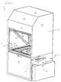
- Figure 1 illustrates a self-contained film processing machine having a light-blocking barrier enclosure 12 including a door 14 movable between open and close positions which defines an opening 16.
- a negative (or positive) image 18 is placed on a glass frame 20 and a film 22 which will later be activated, exposed and heat developed is then placed over it.
- the film 22 is a new generation of image-recording film which is not light sensitive until an electric charge is applied to activate the film afterwhich it is exposed and subsequently heat developed in order to trap an image photographically on the film.
- the barrier enclosure 12 includes a framework 24 which is substantially completely encased by panels 26 in combination with door 14 which when completely closed seals light from entering therein.
- an electrostatic charging carriage 28 is supported on the framework 24 where it is passed over the film as it is held in close parallel proximity to the carrier. Furthermore, a heating element 30 is likewise provided on the framework 24 for heat developing the film 22 as it is passed in contact with the heater which develops the film subsequent to exposing it to light.
- a point light source 32 which is preferably reflected off a mirror 31 is provided in a base portion 33 of the machine beneath the glass frame 20 which exposes the photographic negative (or positive) image 18 on the film 22.
- a microprocessor-based control box 34 is also provided which regulates the activation of valves (to direct the flow of the vacuum pump), cylinders and motion-producing components in machine 10. Furthermore, limit switches are monitored to facilitate control of the machine 10 through the microprocessor-based control box 34.
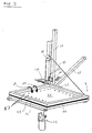
- FIG. 2 shows the film processing machine 10 with selected exterior panels omitted from the framework 24 in order to better depict the layout of internal structural components contained therein.
- Framework 24 includes a charging carriage support frame 36 constructed from a pair of diagonal members 38 and 40 and a horizontal member 42 which supports the charging carrier 28 while it is axially displaced along the diagonal members 38 and 40.
- Glass frame 20 is horizontally supported in the enclosure 12 beneath which the light source 32 is contained for light-exposing the film 22 through glass frame 20 on which the image 18 and film 22 are supported.
- the heating element 30 is horizontally positioned across the back portion of the framework 24 beneath which is pivotally supported a blanket frame 44 which pivots about hinges 46 and 48 between vertical and horizontal positions.
- a vacuum carriage 50 is also provided on framework 24 which is movable between raised and lowered positions therealong for transporting light-exposed film 22 during the development stage of operation.
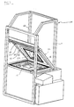
- Figure 4 depicts generally the blanket frame 44 in its closed, or horizontal position.
- Blanket frame 44 is rotatably connected via hinges 46 and 48 to the edge of glass frame 20.
- the glass frame 20 is likewise hingedly connected via hinges 49 which facilitates raising of the glass frame to change and maintain the light source 32.
- Seal 144 is furthermore depicted between frames 20 and 44.
- the blanket frame 44 is rotatably supported inside the enclosure 12 and vacuum engages with the film 22 while in a horizontal position over negative 18 where it is initially placed on the glass frame 20 at the start of an image copying cycle.
- the blanket frame 44 has a substantially flush platen face 52 formed from a sheet of Acrylic which is secured to a larger piece of PVC plastic plate 53, with screws 57 provided substantially about the periphery of inner platen 52 which extend thru plate 52 and a double face tape provided between inner platen 52 and plate 53 into the backside of plate 53 forming a chamber between the pair.
- a foam rubber seal 54 is provided on the outer surface of inner platen 52 substantially about the periphery of said chamber and both the face and seal have perforations 56 which communicate to said chamber through which a vacuum is applied to engage the film 22 against the platen face.
- the platen can be rotated to pick up and carry the film between horizontal and vertical positions.
- a cable 58 is affixed to a top edge of the blanket frame where it passes through a pulley 60 and down to an electric motor and drum 62 which is electrically activated to retract and extend the cable and pivotally raise and lower the blanket frame while transporting a piece of film 22.
- the heating element 30 as depicted in Figure 2 is positioned above the blanket frame 44 when raised to an elevated, or vertical position.
- the heating element 30 is affixed at either end to vertical support bars 61 and 63 on the back of each vertical member 64 and 66, respectively, which form part of framework 24.
- the blanket frame is nested flush between vertical members 64 and 66 in its vertically elevated position, and heating element is positioned vertically above, in slightly spaced-apart relationship.
- the heating element 30 is electrically controlled during operation of the machine 10, in order to apply heat to the film as the vacuum carriage 50 whose operation will be discussed generally hereinafter, passed by it.
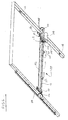
- the vacuum carriage 50 is vertically translated between raised and lowered positions along vertical members 64 and 66 against which it is guided by a pair of linear gear racks 68 and 70 which are affixed to each of member 64 and 66, respectively.
- a pair of rotary gears 72 and 74 provided at either end of the vacuum carriage 50 respectively mate with each of racks 68 and 70.
- Each rotary gear 72 and 74 is held in biased engagement with each rack 68 and 70, respectively, by a pair of rolling contact elements 76 which engage with the opposed back faces of vertical members 64 and 66, respectively, to maintain the rotary gears in meshed engagement with the linear gear racks during vertical motion of the vacuum carriage.
- the pairs of rolling contact elements 76 are provided at each end of the carriage in spaced apart relationship which maintains the vacuum carriage 50 in vertical alignment as it is moved between raised and lowered positions.
- the vacuum carriage 50 includes a main horizontal cross bar 78 which supports a vertical frame 80 therealong. Spaced apart pairs of the rolling contact elements 76 are affixed to the cross bar 78 in order to maintain the vertical alignment of the frame 80 between vertical members 64 and 66 during motion of the carriage therebetween.
- a pair of rotary bushings 82 and 84 support a rotary shaft 86 on the cross bar 78, and a rotary gear 72 and 74 is affixed at either end, respectively.
- a cable 87 is connected to cross bar 78 and passes through a pair of pulleys 88 and 89 on support frame 36 arranged above the vacuum carriage 50.
- An electric motor and drum 90 receives the other end of cable 87 to electrically raise and lower vacuum carriage 50 while it is transporting an exposed piece of film.
- the microprocessor-based control box 34 directs and controls activation of motor 90 in order to heat-develop a piece of exposed film as it is passed in contact with the heater element.
- Vacuum carriage 50 is constructed and arranged to facilitate the lowering of the carriage substantially adjacent the blanket frame as it vacuum supports an exposed piece of film.
- the lowered carriage 50 is then biased in contact with the film 22 along a portion which laterally extends from the frame 80 in order to engage and pick up the piece of film 22.
- the engaged portion is then retracted and the carriage 50 is transported vertically past the heating element 30 in order to develop the exposed film.
- the engaging portion consists of a pair of horizontal vacuum bars 94 and 96 which are connected to top and bottom edges of frame 80, respectively, in horizontal arrangement, which are inwardly biased upon demand through extension and retraction of pneumatic cylinders 98 through which they are mounted to frame 80.
- the pneumatic cylinders When extended, the pneumatic cylinders engage the vacuum bars against a piece of film 22 which is vacuum supported in a vertical configuration on blanket frame 44.
- cylinders 98 By lowering the vacuum carriage 50 to a lowered position substantially parallel with the blanket frame, cylinders 98 are pressurized so that they extend and engage the vacuum bars 94 and 96 against the top and bottom edges of the piece of film 22.
- Vacuum bars 94 and 96 both preferably have an elongated piece of foam rubber 100 on their engaging faces which have perforations 102 through which a vacuum is applied while engaged with the film.
- the bars support and carry the film away from the blanket frame, afterwhich it is raised toward an upward position and passed in contact with heating element 30 which heat develops the exposed film.
- the vacuum on blanket frame 44 is released such that the film is completely supported between bars 94 and 96 in a vertical configuration.
- the vacuum bars 94 and 96 are actuated between extended and retracted positions by pairs of top and bottom cylinders 98 which converge at a slight angle as they are extended such that each bar axially extends from frame 80 at a slight incline toward the other bar so that extension of each bar decreases their spaced apart relative outer end positions as they contact a piece of film carried on the blanket frame 44.
- the cylinders 98 are retracted which increases their spaced apart relation, thus assuring that a positive tension is maintained on the film between the top and bottom horizontal edges, along bars 94 and 96 with which they are vacuum retained.
- a pair of top and bottom positive clamps 103 and 105 are then activated to clamp the film along bars 94 and 96, respectively, to further secure the film.
- motor 90 is energized to raise the carriage and film vertically.
- pneumatic cylinder 107 is activated causing the heating element to be pushed forward in close proximity to the film.
- the heating element 30 consists of a tubular heater inside of a rectangular copper bar which has a flush face with perforations 109 through which a low level vacuum is then applied to pull the film in physical contact with the heater element in order to heat develop the film as it is passed vertically therealong.
- the electrostatic charging conveyor 28 is moved between raised and lowered positions along support frame 36 through the action of an electric motor drive 104 affixed to a cross bar 106.
- the cross bar 106 has a pair of rotary bushings 108 and 110 which support a rotary shaft 112 including rotary gears 114 and 116 affixed at either end.
- a sprocket gear 118 is coupled via a chain 120 to the motor drive 104 such that the motor is electrically actuated to drive the sprocket and shaft which rotates the gears 114 and 116 and raises or lowers the carriage therealong.
- a pair of linear gear racks 122 and 124 are provided on diagonal members 38 and 40, respectively, against which the rotary gears 114 and 116 rotate in gearmeshed engagement.
- Spaced-apart pairs of rotary bushings 126 are provided on a back face of each gear rack, respectively, which maintain each gear in engagement with each rack, as well as support the cross bar 106 in planar relationship with the support frame 136 as they rotate in engagement with the back face of each rack.
- An electrical charging wire 119 is carried on charging carrier 28 to electrically charge and activate a piece of film 22 vacuum supported on carriage 50 while held in an inclined position between diagonal members 38 and 40.
- the wire 119 is stretched across a mounting plate 121 from which it is separated at either end by a spacer block, and the plate is further carried on brackets 123 where it is detachably mounted with screws 125.
- the wire 119 is electrically charged under the direction of microprocessor-based control box 34 while carriage 28 is past completely over the surface of a blanket-frame mounted piece of film 22.
- a first magnetic proximity switch 128 is affixed to the outer frame edge of glass frame 20 to detect the horizontal placement of blanket frame 44 therealong.
- a second magnetic proximity switch 130 is mounted on diagonal member 38 to sense the rotated positioning of blanket frame 44 between diagonal members 38 and 40 prior to electrically charging a supported piece of film with carriage 28.
- a third magnetic proximity switch 132 is supported on vertical member 64 at a location which detects the vertical positioning of blanket frame 44 between the vertical members 64 and 66.
- a spring-biased plunger rod 134 engages the backface of blanket frame 44 to produce a positive bias against the raised blanket frame 44 which downwardly drives the frame when it is lowered.
- Figure 6 depicts a wand-activated electrical trigger switch 136 and 138 provided at the topmost and lowermost rack positions.
- trigger switch 136 and 138 When the charging carriage contacts each trigger switch, power to motor 104 is terminated, and microprocessor-based control box 34 resets the polarity to the motor in order to reverse its direction when power is next re-applied.
- Figure 5 depicts a second set of wand-activated electrical trigger switches 140 and 142 which are mounted on support bars 61 adjacent the uppermost and lowermost positions for vacuum carriage 50. Switches 140 and 142 measure end position of the carriage as they contact a switch which shuts off power to motor 90 and resets microprocessor-based control box 34 to change direction of motor 90 when power is reapplied.
- Each of the various switches 128-142 depicted in the above mentioned figures can be further utilized to monitor safe operation of machine 10 in order to prevent inadvertent start-up of a plurality of motors 62, 90, and 104 when it is not desirable to do so.
- concurrent operation of motor 90 to lower vacuum carriage 50 while motor 62 is raising blanket frame 44 can cause a collision therebetween resulting in significant damage to the respective components.
- microprocessor-based control box 34 can be used to automatically coordinate operation of the machine 10 which directs electrical activation and deactivation of the respective motor components.
- each operation can be separately switch-actuated by a human operator who first loads a negative 18 and film 22 into the machine, and then subsequently closes door 14 to charge, expose, and develop the film within the machine.
- a human operator first positions a negative image (or positive image) onto a glass frame 20 while door 14 is opened, as shown in Figure 1. Subsequently, a piece of film 22 is positioned over the negative 18, and door 14 is subsequently closed which seals out light. A light-tight environment is thereby created inside the enclosure 12 in which the film is activated, exposed, and developed.
- Verde VSX digital film will be utilized in this operating procedure. A Verde VSX digital film requires an activation stage and a development stage during utilization. First, a negative electrical charge is applied to an emulsion side of the film, subsequent to which an image is positioned in vacuum contact thereagainst and a light exposure is provided. Subsequently, the backface of the exposed film 22 is heated which heat develops the film and traps an image photographically therein.
- blanket frame 44 is lowered to a horizontal position as depicted in Figure 3.
- a vacuum is applied via vacuum tube 146 which communicates with the backface of blanket frame 44 to apply vacuum via perforations 56 in platen 52 and seal 54.
- the film 22 is firmly engaged with platen 52 where it is supported thereagainst.
- both film 22 and blanket frame 44 are raised via motor 62 to an angled and elevated position inside carriage support frame 36. Subsequently, motor 104 is activated to first lower the electrostatic charging carriage 28 to a downwardmost position, and then raise carriage 28 while the changing wire 119 is electrically activated to charge the film 22 as carriage 28 is subsequently raised thereadjacent.
- the film 22 is only electrostatically charged by wire 119 during upward motion of the carriage 28. Alternatively, the film could be charged during downward motion, or during both downward and upward motion.
- the unexposed film is sensitized afterwhich it is transported back to its original horizontal position as shown in Figure 3.
- a main vacuum is applied to blanket frame 44 through tube 148 and port 149 in plate 53 outside of platen 52, seal 54, and edges of film 22 to evacuate the air in the space between blanket frame 44 and glass frame 20 and sealed by fully encompassing seal 144 to remove voids and airgaps between the film 22 and image 18, bringing them in intimate contact.
- vacuum is simultaneously applied via vacuum tube 146 to perforations 56 for at least an initial period of time to speed said contact by lessening the trapping of air.
- point light source 14 is activated to expose image 18 onto film 22.
- the said main vacuum is released and blanket frame 44 is raised along with exposed film 22 to a vertical position as shown in Figure 2.
- vacuum carriage 50 is subsequently lowered to a position adjacent with the blanket frame 44 and film 22 as shown in Figure 8.
- vacuum carriage 50 is pneumatically charged which extends pneumatic cylinders 98 and rearwardly biases vacuum bars 94 and 96 in engagement with the film 22 affixed to vacuum carriage platen face 52.
- a vacuum is applied to bars 94 and 96 through corresponding foam rubber seals 100 having perforations 102 such that the film 22 is vacuum engaged with the vacuum carriage 50, as well as the blanket frame 44.
- the vacuum to the blanket frame 44 is released, and pneumatic cylinders which have internal retraction springs are bled which retracts the cylinders, bars 94 and 96, and attached film 22 away from flat face 52.
- vacuum carriage 50 is raised to an elevated position as shown in Figure 5.
- the heating element 30 which is already being maintained at the correct temperature, heats film 22 along its back face as vacuum carriage 50 is vertically raised thereadjacent, exposing the film back face to heating element 30 while it is lifted vertically therealong.
- Application of heat from heating element 30 to the back face of film 22 serves to deactivate and develop the exposed film afterwhich it can be readily handled without affecting its exposed images. It is necessary that the film 22 be heated on the non-emulsion side, or back side or else the emulsion which contacts negative 18 will be damaged.
- the heating element 30 must be in physical contact with the film 22.
- a pair of top and bottom positive clamps 103 and 105 are actuated to clamp the film along bars 94 and 96 before the carriage is raised to an elevated position to further secure the film.
- the carriage 50 is transported vertically such that the top positive clamp 103 is just above heating element 30.
- Air cylinder 107 is then activated causing the heating element 30 to be pushed forward in close proximity to the film.
- a low level vacuum is then applied via perforations 109 in heating element 30 to pull the film in physical contact with the heater element.
- the carriage continues to transport upwards with the film in contact with the heater element 30 until the bottom positive clamp 105 is just short of touching heating element 30.
- the vacuum to heater element 30 is released, air cylinder 107 is deactivated causing the heating element 30 to retract away from the carriage, and top and bottom clamps 103 and 105 are released.
- Vacuum carriage 50 is then lowered back to the position depicted in figure 8, subsequent to which pneumatic cylinders 98 are again actuated, blanket frame 44 is evacuated to engage the film, cylinders 98 are deactivated to release the film from carriage 50, and carriage 50 is raised back to the elevated position of Figure 5.
- the exposed and developed film 22 is retained on vacuum carriage 50 which is pivoted downward to the configuration of Figure 3 subsequent to which a vacuum is released via tube 146, depositing the film on top of the negative 18.
- frame 44 is raised allowing for removal of the exposed and developed film by lowering door 14.
- Utilization of an alternative type of image-recording film requires an activation stage, a deactivation stage, and a heat development stage in order to form and trap an image therein.
- a positive charge is applied to the emulsion side of the film, subsequent to which an image is positioned in vacuum contact thereagainst, and a light exposure is provided.
- a flood lamp exposure is subsequently provided to the emulsion side of the film, and then a negative charge is provided also on the emulsion side to deactivate the film.
- charging carriage 28 first applies a positive charge, and subsequent to exposure applies a negative charge to the film.
- a flood exposure lamp 152 which is shown in dashed lines optionally in Figure 2 is provided behind door 14 in a bottom portion of opening 16. Lamp 152 is activated subsequent to exposure, afterwhich charging carriage 28 is used in combination with blanket frame 44 to transport and negatively charge the film prior to heat development by vacuum carriage 52 and heating element 30.
- a human operator instructs the microprocessor control box, via a switch, which film is being utilized.
Landscapes
- Physics & Mathematics (AREA)
- General Physics & Mathematics (AREA)
- Fluid Mechanics (AREA)
- Exposure And Positioning Against Photoresist Photosensitive Materials (AREA)
Applications Claiming Priority (4)
| Application Number | Priority Date | Filing Date | Title |
|---|---|---|---|
| US339503 | 1989-04-17 | ||
| US30508694A | 1994-09-13 | 1994-09-13 | |
| US305086 | 1994-09-13 | ||
| US08/339,503 US5774203A (en) | 1994-09-13 | 1994-11-14 | Self-contained film exposing/developing machine |
Publications (1)
| Publication Number | Publication Date |
|---|---|
| EP0702262A1 true EP0702262A1 (de) | 1996-03-20 |
Family
ID=26974399
Family Applications (1)
| Application Number | Title | Priority Date | Filing Date |
|---|---|---|---|
| EP95306398A Withdrawn EP0702262A1 (de) | 1994-09-13 | 1995-09-13 | Selbständiges Gerät zum Belichten und Entwickeln eines Filmes |
Country Status (3)
| Country | Link |
|---|---|
| US (1) | US5774203A (de) |
| EP (1) | EP0702262A1 (de) |
| CA (1) | CA2158095A1 (de) |
Families Citing this family (2)
| Publication number | Priority date | Publication date | Assignee | Title |
|---|---|---|---|---|
| SE2151181A1 (en) | 2021-09-27 | 2023-03-28 | Metatarsal implant | |
| WO2026046512A1 (en) | 2024-08-29 | 2026-03-05 | Episurf Ip-Management Ab | Metatarsal implant |
Citations (5)
| Publication number | Priority date | Publication date | Assignee | Title |
|---|---|---|---|---|
| DE1414991A1 (de) * | 1960-03-17 | 1969-04-30 | Rank Xerox Ltd | Vorrichtung zur Induktion von Ladungen |
| US4743948A (en) * | 1985-12-23 | 1988-05-10 | Fuji Photo Film Co., Ltd. | Recording and projecting apparatus |
| EP0418459A2 (de) * | 1989-09-19 | 1991-03-27 | nuArc Company, Inc. | Belichtungsvorrichtung |
| WO1991007693A1 (en) * | 1989-11-17 | 1991-05-30 | Eastman Kodak Company | A contact printer and a method of exposing sensitized graphic art film and paper |
| DE4213399A1 (de) * | 1991-04-23 | 1992-10-29 | Fuji Photo Film Co Ltd | Vorrichtung zum anfertigen von farbproben |
Family Cites Families (7)
| Publication number | Priority date | Publication date | Assignee | Title |
|---|---|---|---|---|
| US3176601A (en) * | 1962-12-03 | 1965-04-06 | James W Bradley | Step-and-repeat machine |
| US3554644A (en) * | 1968-06-19 | 1971-01-12 | Berkey Photo Inc | Photographic printer |
| US3635599A (en) * | 1969-04-04 | 1972-01-18 | Air Reduction | Flame-arresting vent valve |
| US3888586A (en) * | 1974-02-04 | 1975-06-10 | Simco Co Inc | Contact printing apparatus with electrostatic hold-down |
| US4754309A (en) * | 1986-07-25 | 1988-06-28 | Amergraph Corporation | Vacuum frame |
| US4885603A (en) * | 1987-04-02 | 1989-12-05 | Brother Kogyo Kabushiki Kaisha | Image recording apparatus for producing glossy image medium |
| US5204711A (en) * | 1990-06-08 | 1993-04-20 | Nippon Seiko Kabushiki Kaisha | Projection exposure device |
-
1994
- 1994-11-14 US US08/339,503 patent/US5774203A/en not_active Expired - Fee Related
-
1995
- 1995-09-12 CA CA002158095A patent/CA2158095A1/en not_active Abandoned
- 1995-09-13 EP EP95306398A patent/EP0702262A1/de not_active Withdrawn
Patent Citations (5)
| Publication number | Priority date | Publication date | Assignee | Title |
|---|---|---|---|---|
| DE1414991A1 (de) * | 1960-03-17 | 1969-04-30 | Rank Xerox Ltd | Vorrichtung zur Induktion von Ladungen |
| US4743948A (en) * | 1985-12-23 | 1988-05-10 | Fuji Photo Film Co., Ltd. | Recording and projecting apparatus |
| EP0418459A2 (de) * | 1989-09-19 | 1991-03-27 | nuArc Company, Inc. | Belichtungsvorrichtung |
| WO1991007693A1 (en) * | 1989-11-17 | 1991-05-30 | Eastman Kodak Company | A contact printer and a method of exposing sensitized graphic art film and paper |
| DE4213399A1 (de) * | 1991-04-23 | 1992-10-29 | Fuji Photo Film Co Ltd | Vorrichtung zum anfertigen von farbproben |
Also Published As
| Publication number | Publication date |
|---|---|
| CA2158095A1 (en) | 1996-03-14 |
| US5774203A (en) | 1998-06-30 |
Similar Documents
| Publication | Publication Date | Title |
|---|---|---|
| US3208335A (en) | Photographic apparatus | |
| US4571073A (en) | Apparatus for the exposure of photosensitive plates on two sides | |
| US5774203A (en) | Self-contained film exposing/developing machine | |
| JPS6228453B2 (de) | ||
| US3959654A (en) | Dispenser for sheet like material | |
| US4707125A (en) | Photographic registration apparatus and method | |
| US4641940A (en) | Sheet film processing apparatus for exposed sheet film | |
| JPH0468612B2 (de) | ||
| US2846920A (en) | Photocopying and photoprinting apparatus | |
| US3671124A (en) | Microfilm duplicator and method of photocopying microfilms | |
| JP2584816B2 (ja) | 現像装置 | |
| US3371576A (en) | Enlarger easel | |
| JP2667308B2 (ja) | 写真感光材料供給装置 | |
| JPH077210B2 (ja) | 明室操作可能な密着走査露光装置 | |
| JPH10293370A (ja) | 可動形フォトサーモグラフィーフィルムプロセッサ | |
| JP3327678B2 (ja) | カラープルーフ作製装置 | |
| JP2535370B2 (ja) | 現像装置 | |
| JP2811114B2 (ja) | 露光装置 | |
| JPH0446276Y2 (de) | ||
| JP2759080B2 (ja) | 密着露光装置 | |
| JPH01170923A (ja) | シート材の吸気密着方法 | |
| JPH01164944A (ja) | 密着露光装置 | |
| JPH01164946A (ja) | 密着露光装置 | |
| JPH01161352A (ja) | 密着露光装置 | |
| JPH01196064A (ja) | カラープルーフ作成装置 |
Legal Events
| Date | Code | Title | Description |
|---|---|---|---|
| PUAI | Public reference made under article 153(3) epc to a published international application that has entered the european phase |
Free format text: ORIGINAL CODE: 0009012 |
|
| AK | Designated contracting states |
Kind code of ref document: A1 Designated state(s): DE GB |
|
| STAA | Information on the status of an ep patent application or granted ep patent |
Free format text: STATUS: THE APPLICATION IS DEEMED TO BE WITHDRAWN |
|
| 18D | Application deemed to be withdrawn |
Effective date: 19960921 |