EP0702369A2 - Milieu d'enregistrement d'information et dispositif de reproduction d'informations - Google Patents
Milieu d'enregistrement d'information et dispositif de reproduction d'informations Download PDFInfo
- Publication number
- EP0702369A2 EP0702369A2 EP95114567A EP95114567A EP0702369A2 EP 0702369 A2 EP0702369 A2 EP 0702369A2 EP 95114567 A EP95114567 A EP 95114567A EP 95114567 A EP95114567 A EP 95114567A EP 0702369 A2 EP0702369 A2 EP 0702369A2
- Authority
- EP
- European Patent Office
- Prior art keywords
- information
- data
- reproducing
- processing
- error
- Prior art date
- Legal status (The legal status is an assumption and is not a legal conclusion. Google has not performed a legal analysis and makes no representation as to the accuracy of the status listed.)
- Ceased
Links
Images








Classifications
-
- G—PHYSICS
- G11—INFORMATION STORAGE
- G11B—INFORMATION STORAGE BASED ON RELATIVE MOVEMENT BETWEEN RECORD CARRIER AND TRANSDUCER
- G11B27/00—Editing; Indexing; Addressing; Timing or synchronising; Monitoring; Measuring tape travel
- G11B27/10—Indexing; Addressing; Timing or synchronising; Measuring tape travel
- G11B27/102—Programmed access in sequence to addressed parts of tracks of operating record carriers
-
- G—PHYSICS
- G11—INFORMATION STORAGE
- G11B—INFORMATION STORAGE BASED ON RELATIVE MOVEMENT BETWEEN RECORD CARRIER AND TRANSDUCER
- G11B20/00—Signal processing not specific to the method of recording or reproducing; Circuits therefor
- G11B20/10—Digital recording or reproducing
- G11B20/10527—Audio or video recording; Data buffering arrangements
-
- G—PHYSICS
- G11—INFORMATION STORAGE
- G11B—INFORMATION STORAGE BASED ON RELATIVE MOVEMENT BETWEEN RECORD CARRIER AND TRANSDUCER
- G11B20/00—Signal processing not specific to the method of recording or reproducing; Circuits therefor
- G11B20/10—Digital recording or reproducing
- G11B20/18—Error detection or correction; Testing, e.g. of drop-outs
-
- G—PHYSICS
- G11—INFORMATION STORAGE
- G11B—INFORMATION STORAGE BASED ON RELATIVE MOVEMENT BETWEEN RECORD CARRIER AND TRANSDUCER
- G11B27/00—Editing; Indexing; Addressing; Timing or synchronising; Monitoring; Measuring tape travel
- G11B27/10—Indexing; Addressing; Timing or synchronising; Measuring tape travel
- G11B27/19—Indexing; Addressing; Timing or synchronising; Measuring tape travel by using information detectable on the record carrier
- G11B27/28—Indexing; Addressing; Timing or synchronising; Measuring tape travel by using information detectable on the record carrier by using information signals recorded by the same method as the main recording
- G11B27/32—Indexing; Addressing; Timing or synchronising; Measuring tape travel by using information detectable on the record carrier by using information signals recorded by the same method as the main recording on separate auxiliary tracks of the same or an auxiliary record carrier
- G11B27/327—Table of contents
-
- G—PHYSICS
- G11—INFORMATION STORAGE
- G11B—INFORMATION STORAGE BASED ON RELATIVE MOVEMENT BETWEEN RECORD CARRIER AND TRANSDUCER
- G11B27/00—Editing; Indexing; Addressing; Timing or synchronising; Monitoring; Measuring tape travel
- G11B27/10—Indexing; Addressing; Timing or synchronising; Measuring tape travel
- G11B27/34—Indicating arrangements
-
- G—PHYSICS
- G11—INFORMATION STORAGE
- G11B—INFORMATION STORAGE BASED ON RELATIVE MOVEMENT BETWEEN RECORD CARRIER AND TRANSDUCER
- G11B27/00—Editing; Indexing; Addressing; Timing or synchronising; Monitoring; Measuring tape travel
- G11B27/36—Monitoring, i.e. supervising the progress of recording or reproducing
-
- G—PHYSICS
- G11—INFORMATION STORAGE
- G11B—INFORMATION STORAGE BASED ON RELATIVE MOVEMENT BETWEEN RECORD CARRIER AND TRANSDUCER
- G11B7/00—Recording or reproducing by optical means, e.g. recording using a thermal beam of optical radiation by modifying optical properties or the physical structure, reproducing using an optical beam at lower power by sensing optical properties; Record carriers therefor
- G11B7/002—Recording, reproducing or erasing systems characterised by the shape or form of the carrier
- G11B7/0033—Recording, reproducing or erasing systems characterised by the shape or form of the carrier with cards or other card-like flat carriers, e.g. flat sheets of optical film
-
- H—ELECTRICITY
- H04—ELECTRIC COMMUNICATION TECHNIQUE
- H04N—PICTORIAL COMMUNICATION, e.g. TELEVISION
- H04N5/00—Details of television systems
- H04N5/76—Television signal recording
- H04N5/84—Television signal recording using optical recording
Definitions
- This invention relates to an information recording medium such as paper for recording so-called multimedia information containing audio information such as voices and music, video information obtained by a camera, video device or the like, and digital code data obtained by a personal computer, word processor or the like in the form of optically readable code pattern, and an information reproducing device for optically reading a code pattern recorded on the information recording medium and reproducing the original multimedia information.
- multimedia information containing audio information such as voices and music, video information obtained by a camera, video device or the like, and digital code data obtained by a personal computer, word processor or the like in the form of optically readable code pattern
- an information reproducing device for optically reading a code pattern recorded on the information recording medium and reproducing the original multimedia information.
- a group containing some of the inventors of this invention invented a system for recording multimedia information containing at leat one of audio information, video information, digital code data on an information recording medium such as paper in the form of dot code as coded information or image information which can be sent by facsimile transmission and which can be duplicated in large quantities at low cost and a system for reproducing the information and filed the International Application as international application No. PCT/JP93/01377 (International Application KOKAI Publication No. WO 94/08314).
- the dot code pattern itself remains in a stage in which the structure for enhancing the recording density is studied, and the information reproducing device and information recording medium in the above International application are provided without fully taking the flexibility for the future change into consideration.
- This invention has been made in order to solve the above problems, and an object of this invention is to provide an information recording medium and information reproducing device capable of stably reproducing code patterns at high speed and dealing with code patterns even if the code pattern structure itself is changed in the future.
- an information reproducing medium having a portion in which multimedia information containing at least one of audio information, video information and digital code data is recorded in the form of an optically readable code pattern, the information recording medium being applied to restoring means for reading the code pattern and restoring the original multimedia information, the restoring means comprising: first hierarchical processing means for converting the code pattern thus read into code data as an image, adding information relating to the reading to the code data as first processing information, and outputting the resultant information; second hierarchical processing means for recognizing the first processing information output from the first hierarchical processing means, processing code data output from the first hierarchical processing means, creating blocks by collecting the code data for each preset unit, and outputting the blocks; third hierarchical processing means for collecting the blocks output from the second hierarchical processing means, extracting second processing information at least necessary for creating supermacro-blocks of a larger preset unit from the code data of the blocks, recognizing the second processing information, creating supermacro-blocks based on the second
- an information reproducing device for optically reading a code pattern from an information recording medium having a portion in which multimedia information containing at least one of audio information, video information and digital code data is recorded in the form of an optically readable code pattern and restoring the original multimedia information, comprising: first hierarchical processing means for converting the code pattern thus read into code data as an image, adding information relating to the reading as first processing information to the code data and then outputting the same; second hierarchical processing means for recognizing first processing information output from the first hierarchical processing means to process code data output from the first hierarchical processing means, creating blocks by collecting the code data for each preset unit, and outputting the blocks; third hierarchical processing means for extracting second processing information at least necessary for creating supermacro-blocks of a larger preset unit by collecting the blocks output from the second hierarchical processing means from the code data of the blocks, recognizing the thus extracted second processing information, creating supermacro-blocks based on the second processing information, extracting third processing information
- an information reproducing device for optically reading a code pattern from an information recording medium having a portion in which multimedia information containing at least one of audio information, video information and digital code data is recorded in the form of an optically readable code pattern and restoring the original multimedia information, comprising: first hierarchical processing means for converting the code pattern thus read into code data as an image, adding information relating to the reading as first processing information to the code data, and then outputting the same; second hierarchical processing means for recognizing first processing information output from the first hierarchical processing means to process code data output from the first hierarchical processing means, creating blocks by collecting the code data for each preset unit, and outputting the blocks; third hierarchical processing means for extracting second processing information at least necessary for creating supermacro-blocks of a larger preset unit by collecting the blocks output from the second hierarchical processing means from the code data of the blocks, recognizing the thus extracted second processing information, creating supermacro-blocks based on the second processing information, extracting third
- an information reproducing device comprising: scanning means for optically reading a code pattern from an information recording medium having a portion in which multimedia information containing at least one of audio information, video information arid digital code data is recorded in the form of an optically readable code pattern; restoring means for restoring the code pattern read by the scanning means into original multimedia information; and error informing means for informing occurrence of error when the original multimedia information cannot be restored by the restoring means while determining whether the cause of non-reproduction is caused by an error occurring in the processing process by the scanning means or restoring means or by the fact that the information reproducing device is not applicable to the code pattern read by the scanning means.
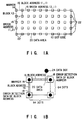
- a dot code 10 is constructed by arranging a plurality of blocks 12 each of which is constructed by a plurality of dots arranged according to the content of data. That is, the blocks 12 which are treated as data for every given unit are collectively arranged.
- Each of the blocks 12 is constructed by a marker 14, block addresses 16, address error detection data 18, and a data area 20 into which actual data is set.
- the blocks 12 constructing the dot code 10 are arranged in a two-dimensional form and the block addresses 16 are added to each of the blocks.
- An address for the X and Y addresses is attached to the block address 16.
- the X and Y addresses of a block lying in the uppermost and leftmost position are set to (1, 1).
- the block address of a block lying on the right side of the above block is set to (2, 1).
- a block address obtained by incrementing the X address for a block lying in the farther position in the right direction and incrementing the Y address for a block lying in the farther position in the downward direction is attached to the block, and thus the block address 16 is attached to each of the blocks 12.
- Markers lying in the downmost position and markers lying in the rightmost position are treated as dummy markers 22. That is, the block 12 for one of the markers 14 is data in an area surrounded by four markers 14 containing the above marker and lying in the lower right position with respect to the above marker, and the markers in the lowermost position and rightmost position are auxiliary markers arranged to define the blocks lying in the second positions from the lowermost and rightmost positions, that is, dummy markers 22.
- a block address 16 and error detection data 18 of the block address are attached between the marker 14 of the block 12 and a lower marker thereof.
- a block address 16 and error detection data 18 of the block address are attached between the marker 14 of the block 12 and a marker on the right side thereof.
- the block addresses 16 are arranged on the left side and upper side of the data area 20 and the marker 14 is arranged on the upper left corner of the data area.
- the block addresses 16 are recorded on two portions of one block is shown, but it is possible to record the block address in one portion.
- the block address can be reliably detected by detecting one of the two block addresses even if noise is superposed on the other block address and an error occurs, and therefore, it is preferable to record the block addresses in two portions.
- the each of data dots 24 in the data area 20 has the dot size of several ten ⁇ m, for example.
- the size of the data dot may be reduced to several ⁇ m depending on applications or purposes of usage, but in general, the size is set to 40 ⁇ m, 20 ⁇ m or 80 ⁇ m.
- the data area 20 has the size of 64 ⁇ 64 dots.
- the sizes can be freely enlarged or reduced in a range in which an error caused by the equal division can be neglected.
- the marker 14 has a function of position index and is set to have the size which modulated data does not have, and may be formed in a circular form with the size of seven or more dots of the data dots 24, for example, or formed as a black circular mark with the size of approx. 7 ⁇ 7 dots.
- the block address 16 and error detection data 18 are constructed by the same dots as the data dots 24.
- the hierarchical segmentation includes a plurality of logical hierarchical structures of the layers 1 to 5 on both of the recording and reproducing sides.
- multimedia information caused in an application process X
- an application program on the computer containing audio information such as voices and music, video information derived from a camera or video device, and digital code data obtained from a personal computer or word processor is transferred to an MMP recording device 26 used as an information recording device via the application layer (layer 5) and presentation layer (layer 4) constructed on the computer.
- received data is printed or recorded on an information recording medium (transmission medium) 30 such as paper as an optically readable dot code pattern by the data link layer (layer 3), block data layer (layer 2) and physical layer (layer 1).
- the information recording medium (transmission medium) 30 is handed over to the reproducing side.
- the code pattern recorded on the medium 30 can be sent to the reproducing side by facsimile and printed or recorded on the information recording medium 30 such as paper on the reproducing side.
- the code pattern recorded on the information recording medium 30 is photographed, the data editing process is effected according to the restoring processing procedure from the layer 1 to the layer 3 or to the layer 5 in the reverse order of the order at the recording time, and resultant data is given to the reproducing side computer.
- the reproducing side computer reproduced multimedia information is given to the application process (application program) Y via the processing function of the layers 4 and 5, if necessary, in the reverse order of the order on the recording side.
- each layer (hierarchy) of the reproducing side is explained in detail, and since the layers of the recording side are just opposite to those of the reproducing side, the explanation therefor is omitted.
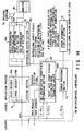
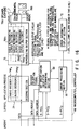
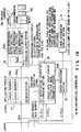
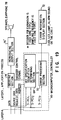
- FIG. 3A and FIG. 3B are diagrams showing an example of the procedure of a process effected over multiple stages by use of a plurality of hierarchical structures on the reproducing side.
- N-SDU n indicates the Nth layer service data unit No. n
- N-PDU n indicates the Nth layer protocol data unit No. n
- N-PCI n indicates the Nth layer protocol control information No. n (corresponding to various processing information in this invention)
- N-UD n indicates the Nth layer user data No. n
- ADU indicates the application data unit
- the layer 1 plays a basic role of ensuring reliably transmission of quantization data of a dot image.
- the layer 1 defines electrical/physical conditions and various conditions for quantization (that is, simple transfer rule of the dot pattern, equalization system, quantization system and the like).
- the intra-layer function required for the layer 1, that is, the service provided therefor includes provision of a plurality of transmission media (paper types), permission of plural dot density, provision of a plurality of scanner resolutions, provision of a plurality of transmission means for video signals, and provision of reading starting/ending function, and it may further include representation of a plurality of gradations (binary value, multiple values) of dots, and permission of multiplexed representation of dots (color image photographing, transmission) as required.
- the layer 1, that is, the physical layer has a functional module (photographing-system module 32) of optically photographing or picking up a dot code pattern recorded on the information recording medium (transmission medium) 30 such as paper and outputting an image signal, and a functional module (reproduction equalizing module 34, quantization module 36) of subjecting an image signal to the pre-processing (gain control, equalization processing) and then sampling/quantizing the signal.
- a functional module photographing-system module 32
- reproduction equalizing module 34, quantization module 36 of subjecting an image signal to the pre-processing (gain control, equalization processing) and then sampling/quantizing the signal.
- a functional module of converting the quantized value into digital data to create image data a functional module of forming image data into a structure form to convert the data into a given data format constructed by structure information (header, that is, first processing information) and data (substance of image data) and outputting the same to an adjacent upper layer, that is, the layer 2, a functional module of inputting/outputting status information and control information relating to the process and the like.
- Structured (image) data of photographing frame unit is given from the layer 1 to the upper layer 2 as a service data unit (1-SDU1).
- the layer 2 plays a basic role of reliably transmitting a block and a bit string in the block (in-block bit string).
- the layer 2 defines various conditions (that is, block detection system, channel bit detection system, coding modulation/demodulation system, and the like) for block transmission.
- the intra-layer function required for the layer 2, that is, the service provided therefor includes block extraction and detection of dot sampling points, provision of a plurality of recording systems (provision of binary value, multiple values, multiplexed system and the like), provision of a plurality of block patterns, provision of a plurality of coding modulation/demodulation systems, detection of the relative position of the block, information of block detection error, obstruction overcoming operations and the like.
- provision of a plurality of block patterns includes a block size detection function, marker definition/detection function, adaptation of the readout order of various dots and the like.
- the layer 2, that is, the block data layer includes a functional module of receiving structured (image) data (1-SDU1) input from the adjacent lower layer, that is, the layer 1 as 2-PDU1, recognizing and dividing the structure information (2-PDI1, that is, first processing information) and data substance (2-UD1), and converting the data substance into a suitable form for the process, a functional module (block-unit dot detection point extraction (marker detection, pattern matching and the like) module 38, dot detection (identification/determination module 40) of processing the data substance converted into the suitable form for the processing and extracting a plurality of blocks formed in a block form for every given information code unit, and a functional module (block ID data reproducing module 42, in-block data reproducing module 44) of processing the extracted block and reproducing the information code of block unit.
- a functional module block-unit dot detection point extraction (marker detection, pattern matching and the like) module 38, dot detection (identification/determination module 40) of processing the data substance converted into the suitable form for the processing and
- the information code of block unit contains data substance, coding modulation information and structured information for linking a plurality of blocks.
- the layer 2 has a functional module (coding demodulation module 46) of reading the coding modulation information from the information of block unit and demodulating the data substance according to the coding modulation information, a functional module of outputting structured data (block header, that is, second processing information) of the demodulated block-form information code and data substance (user data) to the adjacent upper layer, that is, the layer 3 as 2-SDU1, a functional module of inputting/outputting control information and status information relating to the processing, and the like.
- coding demodulation module 46 of reading the coding modulation information from the information of block unit and demodulating the data substance according to the coding modulation information
- a functional module of outputting structured data (block header, that is, second processing information) of the demodulated block-form information code and data substance (user data) to the adjacent upper layer, that is, the layer 3 as 2-SDU1
- a block unit dot detection point or marker is detected from image data for every block data which is the first given unit, and data dots are detected for every block unit according to the detected marker to restore data of bit string.
- the detail of the processing is described in International Application No. PCT/JP93/01377 (International Application KOKAI Publication No. WO 94/08314).
- For data of the block unit a header or block ID data is reproduced, then in-block data is reproduced as user data, demodulation for coding is effected and the data is given to the upper layer, that is, the layer 3 as data of block data unit.
- the layer 3 plays a basic role of creating a given data mass (subset element (fourth given unit)) which is ensured to have a preset error quality and ensuring reliably transmission.
- the layer 3 defines conditions for linking block data (first given unit) and various conditions (that is, interleave system/structure) for creating macro-blocks (third given unit)/supermacro-blocks (second given unit), (super) macro-block header and user data error control (that is, ECC system/structure) and the like.
- the intra-layer function required for the layer 3, that is, the service provided therefor includes provision of a function of restoring an abnormal condition of block address reading/writing, determination of a reading state of a desired block (checking of a block of valid reading), setting of block arrangement structure, creation of intermediate data masses, provision of a plurality of interleave systems/ranges/structures, provision of a plurality of ECC systems/ranges/structures, and the like.
- the layer 3, that is, the data link layer has a functional module (block link (macro-block creation) module 48) of receiving a block-formation information code (2-SDU1) input from the adjacent lower layer, that is, the layer 2 as 3-PDU1, recognizing and reading structured information (3-PCI1, that is, second processing information) from the input code, and linking a plurality of data substances (3-UD1) of block unit according to the structured information to create (construct) a macro-block or supermacro-block.
- a functional module block link (macro-block creation) module 48 of receiving a block-formation information code (2-SDU1) input from the adjacent lower layer, that is, the layer 2 as 3-PDU1, recognizing and reading structured information (3-PCI1, that is, second processing information) from the input code, and linking a plurality of data substances (3-UD1) of block unit according to the structured information to create (construct) a macro-block or supermacro-block.
- the block unit receives bit data strings in the block unit from the layer 2, recognizes and divides a block header as 3-PCI1 (second processing information) of a given number of bits from the head of each block and a user data as 3-UD1, and linking blocks according to information described in the block header to create a macro-block.
- the thus created macro-block is constructed by attached information (macro-block header, that is, one of second processing information) dispersedly arranged in the block and data substance (user data).
- the layer 3 has a module (macro-block header unit de-interleave/error correction module 50) of reading the interleave information from the macro-block header, de-interleaving the user data of the macro-block according to the interleave information, reading the error correction information from the macro-block header, and performing the error correction process to the de-interleaved user data according to the error correction information, a functional block (macro-block link (supermacro-block creation) module 52) of reading structured information for creating (constructing) a supermacro-block from the macro-block header, and linking a plurality of macro-blocks according to the structured information to create (construct) a supermacro-block, a functional module (supermacro-block unit de-interleave module 54) of reading interleave information from the macro-block header and de-interleaving user data of the supermacro-block according to the interleave information, a functional module (supermacro-block unit error correction
- the layer 3 has a multi-stage function of first linking or coupling the blocks to create a macro-block and then linking the macro-block to a supermacro-block. Then, after the error correction process, it reads the subset structure specification (third processing information) described in the macro-block header, separates the supermacro-block into data corresponding to the concept of subset elements, and outputs the subset elements. That is, data is given to the upper layer as 3-SDU1 in the unit of subset element.
- the layer 4 plays a basic role of ensuring creation of a subset.
- the layer 4 defines various conditions for linking subset elements to create a subset.
- the intra-layer function required for the layer 4, that is, the service provided therefor includes selection of subset elements necessary for an object file, creation of the subset and determination of the condition therefor, and adaptable data conversion for DOS or the like.
- the subset indicates recognizable information unit data. That is, the macro-block and supermacro-block contain multimedia information such as sound and picture and each of data masses obtained by dividing the above block into data masses each of which is limited to information relating only to sound or information relating only to picture so as to be recognized as one type of information unit is called a subset.
- the layer 4, that is, the presentation layer has a functional module (subset element link information reading module 60) of receiving data (3-SDU1) of subset element unit input from the adjacent lower layer, that is, the layer 3 as 4-PDU1 and reading structured information (4-PCI1, that is, fourth processing information) from the received data, and a functional module (subset element link (subset creation) module 62) of linking data substances of subset element unit according to the read structured information to create (construct) a subset.
- Data of subset element unit is constructed by structured information (subset element header) for linking subset elements to create (construct) a subset and user data substance.
- the layer 4 has a functional module of reading attached information necessary for an existing or new interface with the adjacent upper layer from the created subset and attaining the interface matching, a functional module of outputting part of the subset or the entire attached information and data substance as 4-SDU1 to the adjacent upper layer, that is, the layer 5, and a functional module of inputting/outputting control information and status information relating to the process.
- the layer 5 (application layer) plays a basic role of unfailingly ensuring that the file management can be carried out in good condition.
- the layer 5 defines various conditions (that is, file creating condition and the like) for effecting the file management.
- the intra-layer function required for the layer 5, that is, the service provided therefor includes provision of the read/write process of a subset or file of application request.
- the layer 5, that is, the application layer has a functional module (file management system module 64) of receiving subset data (4-SDU1) input from the adjacent lower layer, that is, the layer 4 as 5-PDU1, reading file management information from the attached information (5-PCI1, that is, fifth processing information) or data substance (5-UD1), effecting the file management according to the file management information, and reading data in the unit of subset or in the unit of file after linking subsets to create a file, a functional module of outputting data unit of the file unit or subset unit created based on the file management as 5-SDU1 to the application process, and a functional module of inputting/outputting control information and status information relating to the process.
- file management system module 64 of receiving subset data (4-SDU1) input from the adjacent lower layer, that is, the layer 4 as 5-PDU1, reading file management information from the attached information (5-PCI1, that is, fifth processing information) or data substance (5-UD1), effecting the file management according to the file management information, and reading data in the unit of sub
- the application process plays a basic role of realizing the application using the MMP system.
- the application process includes the source sample data shuffling system/structure, scramble system/structure for ciphering, and data compression system/structure, data structure of sound, text or image and the like.
- the function required for the application process includes provision of source sample data shuffling system, provision of scramble system and the like, and it may further include provision of a plurality of data compression systems and compression/expansion operations, determination of information types, selection of data structure and the like, if required.
- This invention relates to the detail of the layer 5 (application layer) and the application process layer in the case of stand-alone type for realizing the hierarchical structure described in Jpn. Pat. Appln. No. 6-121368 (International Application No. PCT/JP95/01050).
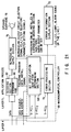
- FIG. 4 is a diagram showing the structure of the first embodiment.
- a microcomputer or controller 66 constructs a set specification identifier determining section 68 and an error processing section 70, and it receives a subset from the layer 4, that is, it receives 4-SDU1 as 5-PDU1, receives 4-SDU2 which is a status signal as 5-PCI2, and receives 4-SDU3 which is a parameter setting signal as 5-PCI3.
- the set specification identifier determining section 68 determines whether the readout code information is a dot code 10 or not, whether it matches with the specification or not, and whether it can be reproduced by use of the hardware or not based on 5-PCI2 and 5-PCI1 among 5-PDU1, and if the result of determination is "NO", it causes the error processing section 70 to effect the error processing operation and causes the error information display section 72 to display the error state. Further, the set specification identifier determining section 68 effects processes of setting parameters for reproduction, setting selection of the decoder of the decoding section 74, and selection of the reproducing output section 76 and the like. Further, it outputs a data request, data address and the like to the layer 4.
- the decoding section 74 receives and decodes 5-UD1 among 5-PDU1 and includes an audio decoder 74A for decoding audio information and an image decoder 74B for decoding image information.
- Text information is output as it is. That is, since a subset or data obtained in the form of data mass which is limited to information relating only to sound, information relating only to image or information relating only to text so as to be recognized as one information unit is input from the layer 4, an adequate decoding process corresponding to the information is effected. For example, in the case of audio information, if data is compressed in the compression system of CELP system in which the information is specified to human languages, a corresponding decoding process is effected in the audio decoder 74A.
- the decoder 74B is selectively operated by a decoder selection signal from the set specification identifier determining section 68.
- the reproducing output section 76 receives a decoded output from the decoder section 74 and converts the same into a signal suitable for the output device and includes an audio reproducing output section 76A, image reproducing output section 76B and text reproducing output section 76C.
- the reproducing output sections 76A, 76B, 76C are selectively operated by a reproducing output circuit selection signal from the set specification identifier determining section 68, and in this case, since the audio reproducing output section 76A is designed to cope with plural types of clocks and filters, for example, the clock and filter for the sampling frequency of 7 kHz or 8 kHz, or the clock and filter for the sampling frequency of 48 kHz of CD quality, the clock and filter can also be selected by the reproducing output circuit selection signal.
- the image reproducing output section 76B converts the image size into 640 ⁇ 480 dots, for example, according to the reproducing output circuit selection signal.
- the text reproducing output section 76C converts text information into characters.
- an output signal of the audio reproducing output section 76A is output as a voice from an audio output device 78 such as a speaker, earphone or headphone. Further, output signals from the image reproducing output section 76B and text reproducing output section 76C are displayed on a display output device 80 such as a monitor.
- the error processing section 70 informs occurrence of error to the user by lighting an alarm lamp of LED, displaying markers or characters by LCD, lighting a red or yellow lamp on the error information display section 72, or generating beep sound or giving warning by voice according to the type of the error.
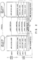
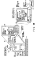
- data is transferred from the layer 4 in the form of subset, and a file header area 84 is exceptionally attached in the front portion of the top subset header area 821 which is first arranged in the subset.
- a file header area 84 is exceptionally attached in the front portion of the top subset header area 821 which is first arranged in the subset.
- three subsets are successively shown to simultaneously indicate cases of audio, image and text information, but in practice, data is transferred for each subset.
- a next subset data control header (SDCH) pointer 84A, set specification name identifier 84B and information 84C indicating the presence/absence of SDCH are inserted.
- SDCH data control header
- UDF user data format
- the next SDCH pointer 84A takes an area of four bytes and designates a head address of the next SDCH.
- the set specification name identifier 84B includes a file specification name (for example, "m, p, 1") 84B1 of three bytes, file specification version 84B2 of three bytes, and set specification name and set specification version 84B3 and 84B4 of eight bytes in total.
- the set specification name 84B3 indicates the specification name to make it unnecessary to refer to each SDCH in a case where the specification value of each SDCH is determined by the individual specification.
- the presence/absence-of-SDCH indicating information 84C indicates the presence or absence of SDCH.
- subset header areas 821, 822 and 823 different information items corresponding to the types of data items inserted into the data areas 881, 882 and 883 of the corresponding subset are inserted.
- the subset area 821 indicates a case wherein audio data is inserted into the data area 881, and the subset data control header (SDCH) 8211 is constructed by a user data format (UDF) 8211a, next SDCH pointer 8211b, parameter 8211c, and data area starting and ending addresses 8211d, 8211e.
- SDCH subset data control header
- the UDF 8211a indicates the type of data inserted into the corresponding data area 881, and in this case, information of "audio" is inserted.
- next SDCH pointer 8211b the head address of SDCH of the next subset header is inserted.
- the absence of a next subset is indicated by inserting a value, for example, "FF H ( H indicates a hexadecimal number)" or "00 H " which the content of the next SDCH pointer cannot take as an address.
- a parameter for audio is inserted, and the following information items are inserted, for example.
- information of "audio data is present” indicates whether audio information is present or not
- information of "stereo” indicates whether data is stereo or not.
- Information of "R/L order” indicates whether the arrangement of data is “right, left” or “left, right” in the case of stereo.
- Information of "reservation” indicates an available area to be used later when an additional parameter is provided.
- Information of "compression system” specifies the compression system such as CELP system, and information of "quantization bit number” indicates that the quantization bit number is 8 bits, 16 bits or 14 bits, for example.
- Information of "sampling frequency” indicates that the sampling frequency is 8 kHz, 16 kHz, 32 kHz or 48 kHz, and information of "data size” indicates the amount of total data in the data area 881.
- the head address and end address of the corresponding data area 881 are inserted.
- the subset header area 822 indicates a case wherein image data is inserted into the data area 882, and the SDCH 8221 is constructed by a UDF 8221a, next SDCH pointer 8221b, parameter 8221c, and data area starting and ending addresses 8221d, 8221e.
- the parameter 8221c the following information items are inserted, for example.
- information of "color system” indicates whether image data is a color image or black and white image, and if it is a color image, the information also indicates whether the image data is based on RGB, or on cyan, magenta and color difference component.
- Information of " ⁇ characteristic” indicates whether the ⁇ characteristic is 1 or 0.45
- information of "compression system” indicates the compression system such as JPEG system.
- Information of "quantization bit number” indicates 8 bits, 6 bits or 10 bits or more which is more precise.
- information items of "horizontal pixel number” and "vertical pixel number” define the size of an image plane used for forming a 2-dimensional image. For example, it indicates whether the image is a so-called VGA image of 640 ⁇ 480 dots or a high-resolution image such as a so-called SVGA image of 1260 ⁇ 1090 dots.
- the subset header area 823 indicates a case wherein text data is inserted into the data area 883, and the SDCH 8231 is constructed by a UDF 8231a, next SDCH pointer 8231b, parameter 8231c, and data area starting and ending addresses 8231d, 8231e.
- the parameter 8231c the following information items are inserted, for example.
- compression system in the decoding section 74 in FIG. 4 is made based on the assumption that text data is not compressed, but it becomes necessary to compress the data when the amount of data becomes large, and the compression system used in such a case is described here.
- Data items in the file header area 84 and subset header areas 821, 822, 823 are supplied to the set specification identifier determining section 68 as 5-PCI1 and data items in the data areas 881, 882, 883 are input to the decoding section 74.
- FIG. 6 is a flowchart of the reproducing process with the construction of FIG. 4.
- the set specification identifier determining section 68 reads 5-PCI2 which is a status signal (step 11) and checks whether a subset is completed or not (step S12). Since data is transferred from the layer 4 to the layer 5 when the data for one subset unit is obtained and a status signal indicating that the data for one subset unit is obtained or the subset can be output is supplied as 5-PCI2, it becomes possible to determine whether the subset is completed or not according to the signal. If the subset is not yet completed, the step S11 is effected again.
- step S13 whether or not an error is generated in the process effected up to the layer 4, that is, whether or not block data has been read as a code or whether or not the error correction has been completely effected in the error correcting process can be determined.
- step S14 If the error information is not good, that is, if the error is present, an error flag E is set to "1" (step S14) and then the error process as will be described later is effected (step S15). That is, the error processing section 70 effects the error display corresponding to the type of error by lighting an alarm lamp of LED, displaying markers or characters by LCD, lighting a red or yellow lamp on the error information display section 72, or generating beep sound or giving warning by voice, for example.
- the set specification identifier determining section 68 effects the process of determining the set specification name identifier 84B of the file header area 84 among 5-PCI1 (step S16). Whether it is a reproducible code or not is determined according to the set specification name identifier 84B. The process is explained in detail later.
- step S17 the decode mode and reproducing parameter setting process which is described later in detail is effected (step S17). That is, a decoder selection signal, reproducing output circuit selection signal and parameters such as a clock and filter necessary for the reproducing process are extracted and set according to 5-PCI1.
- the decoder selection signal is input to the decode section 74, the reproducing output circuit selection signal and parameters are input to the reproducing output section 76, and various parameters are set and selected.
- the audio decoder 74A is selected by the decoder selection signal and the input data is subjected to the decoding process by the audio decoder 74A. Then, the audio data is passed through the audio output section 76A selected by the reproducing output circuit selection signal and corresponding to the voice having parameters set therein and reproduced and output from the audio output device 78 such as a speaker or earphone.
- the data is supplied via the image decoder 74B and image reproducing output section 76B and displayed on the display output device 80 such as a monitor, and if it is determined that data is text data, the data is supplied via the decoding section 74 as it is, converted into characters by the text reproducing output section 76C and displayed on the display output device 80.
- FIG. 7 is a flowchart for illustrating the set specification name identifier determining process in the step S16 in detail.
- the counter S is initialized to "4" and the counter k is initialized to "0" (step S21).
- the reason why the counter S is set to "4" is that the next SDCH pointer 84A of the file header area 84 is set to four bytes as described before, and if it is set to six bytes, the counter S is set to "6".
- the counter k simply functions as a loop counter, and therefore, a value "0" is set as an initial value.
- a value (A+S) is set into an address counter a and a value (i+k) is set into a counter i (step S22).
- A indicates a head address of the file header area 84, and therefore, if the value of the counter S, in this example, "4" is added to the value of A, the content of the address counter a indicates the head address of the set specification name identifier 84B.
- the pattern Mi is constructed as "m, p, 1, 1, 0, 0, O, L, Y, S, 1, 1, 0, 0", for example. That is, the first three bytes “m, p, 1" correspond to the file specification name 84B1 of the set specification name identifier 84B, the next three bytes “1, 0, 0” correspond to the file specification version 84B2 of the same, and the following bytes “O, L, Y, S, 1, 1, 0, 0" correspond to the set specification name and set specification version 84B3 and 84B4 of 8 bytes. That is, this example indicates "mp1 version 1.00, OLYS1 version 1.00".
- the set specification name 84B3 indicates the specification name so as to omit the necessity of referring to each SDCH if the specification value of each SDCH is determined by the individual specification. For example, the sound source, compression system and sampling rate are determined by "S1".
- a plurality of patterns Mi are prepared and, for example, if the set specification name 84B3 is "V1”, the audio source, compression system and sampling rate are determined, if it is “I1”, the image source, compression system and display size are determined, and if it is "T1", the text source and file form are determined.
- step S23 whether or not the pattern Ma (bytes indicated by the address a ) of the set specification name identifier 84B coincides with the pattern Mi (bytes indicated by i) stored in the memory (not shown) is determined (step S23), if the former pattern coincides with the latter pattern, whether the value of the counter k has reached n or not is determined (step S24), if it is determined that it has not reached n, the values of the counters S and k are incremented by "1" (step S25), and the process returns to the step S22 to compare the next byte data.
- step S23 if it is determined in the step S23 that the former pattern does not coincide with the latter pattern, "2" is set into the error flag E (step S26) and then the error process in the step S27 is effected.
- the error processing section 70 first determines whether the error flag E set by the set specification identifier determining section 68 is "2" or not (step S31). In the error process in the step S15, since the error flag E is set at "1", scanning error and instruction of re-scanning are displayed (step S32). For example, when the scanning section for effecting the process in the layer 1 and the restoring section for effecting the processes of the other layers are constructed in different casings, the error information display section 72 is constructed to contain error information display sections mounted on the respective casings. Therefore, display in the case where the error flag E is set at "1" is attained by an error display information section mounted on the scanning section (not shown).
- step S33 if the error flag E is set at "2", that is, in the case of error processing in the step S27, whether the value of the counter S is less than "9", that is, whether non-coincident byte is detected during the comparison of a portion of the file form name and file version of "m, p, 1, 1, 0, 0" which is the front half of the pattern Mi is determined (step S33).
- step S34 the file-off-specification code is displayed.
- the second processing routine is used in the case of applicable type, that is, when the hardware is applicable even if the code is off-specification, and in this case, it is recognized that the code is a non-registered code of MMP specification, and a corresponding processing routine is effected to reproduce and output data in the same manner as described before (step S35). That is, even if the error flag E is set at "2", it is determined that no error has occurred and a next step is effected when the hardware is an applicable type, but the error is displayed when the hardware is not an applicable type.
- step S36 display of non-reproducible state corresponding to the error state is effected (step S36).
- the error display in the above steps S32, S34, S36 is attained, for example, by lighting an alarm lamp of LED, displaying markers or characters by LCD, lighting a red or yellow lamp on the error information display section 72, or generating beep sound or giving warning by voice according to the type of the error, but it is possible to inform the type of error to the user by displaying the contents of the scanning error display, re-scanning instruction display, off-specification code display and non-reproducible display in different manners, for example, by lighting the red lamp for the scanning error, lighting the yellow lamp for the off-specification code.
- the set specification identifier determining section 68 sets the value of the next SDCH pointer 84A of the file header area 84 into the address counter a (step S41), reads UDF lying in the address, for example, UDF 8211a of the subset header area 821, determines the media, for example, voice, outputs a decoder selection signal to the decoding section 74 so as to select the audio decoder 74A, and outputs a reproducing output circuit selection signal to the reproducing output section 76 so as to select the audio reproducing output section 76A (step S42). Then, it reads the content of the next SDCH pointer 8211b of the next address (in this case, "FF H " indicating that no SDCH is present is set) (step S43).
- step S44 the content of SDCH, that is, the parameter 8211c is read (step S44) and the parameter is set (step S45). That is, the parameter setting is effected by the reproducing output circuit selection signal. Then, whether the reading of SDCH data, that is, parameter 8211c is completed or not is determined (step S46), and if it is not yet completed, the step S44 is effected again and the process of reading the next parameter is repeated. That is, since it is already determined that data is audio data by the UDF 8211a and the address range of the parameter 8211c is determined by the specification in the case of audio data, whether the reading of the parameter is completed or not can be determined by determining the address.
- step S47 the data area starting address 8211d and data area ending address 8211e for the corresponding data area 881a are read and stored into a memory (not shown) (step S47).
- FIGS. 10 and 11 are diagrams showing the construction of the second embodiment of this invention and the flowchart of the reproducing process and portions which are the same as those of FIGS. 4 and 6 are denoted by the same reference numerals.
- the construction of this embodiment is different from the construction of the first embodiment in that the set specification identifier determining section 68 includes UDF, SDCH reading section 68A for reading the UDF and SDCH.
- the file structure in which a plurality of subsets are successively arranged and a file header area 84 is arranged only in front of the first subset as shown in FIG. 5 is transferred from the layer 4.
- the UDF, SDCH reading section 68A of the set specification identifier determining section 68 does not terminate the process after one subset is reproduced and output in the step S19, but determines whether the reproducing process for all of the subsets is completed or not (step S51), and if it is not yet completed, the step S17 is effected again and the reproducing process for the next subset data is effected. That is, in the example shown in FIG. 5, audio data is first reproduced, image data is next reproduced and then text data is reproduced.
- FIG. 12 is a diagram showing the file structure in the third embodiment of this invention and portions which are the same as those of FIG. 5 are denoted by the same reference numerals.
- one subset header is attached to each subset, but since data starting addresses 8211d, 8221d, 8231d and ending addresses 8211e, 8221e, 8231e are respectively provided in the subset header areas 821, 822, 823 for corresponding data areas 841, 842, 843, it is not necessary to successively arrange the header areas 821, 822, 823 and the data areas 841, 842, 843, and it is possible to collectively arrange the subset header areas 821, 822, 823 as shown in FIG. 12.
- the flowchart for the reproducing process is the same as that of FIG. 11 of the second embodiment.
- the UDF, SDCH reading section 68A of the set specification identifier determining section 68 collectively reads the subset header areas 821, 822, 823 in the set specification name identifier determining process of the step S16.
- the process of selecting the decoder 74A, 74B and reproducing output section 76A, 76B, 76C and setting parameters is effected.
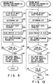
- the parameter setting process may be effected to collectively set the parameters at the first time. That is, as shown in FIG. 13, the value of the next SDCH pointer 84A of the file header area 84 is set into the address counter a (step S41), UDF lying in the address is read and the content thereof is stored into a memory (not shown) (step S42), and then the content of the next SDCH pointer 8211b is read (step S43). After this, the content of the SDCH, that is, the parameter is read (step S44), and the parameter is set into a corresponding reproducing output section (step S45).
- step S46 whether reading of SDCH data, that is, parameter is completed or not is determined (step S46), and if it is not yet completed, the step S44 is effected again and the process of reading the next parameter is repeated.
- step S47 When setting of all of the parameters is completed, a data area starting address and data area ending address for a corresponding data area are read and stored into a memory (not shown) (step S47).
- step S48 whether the reproducing process for all of the subsets is completed or not is determined (step S48), and if it is not yet completed, the step S41 is effected again and the process of storing UDF of the subset and address and setting parameters is repeated.
- the program for the controller 66 can be simplified.
- FIG. 14 is a diagram showing the construction of the fourth embodiment of this invention and portions which are the same as those of FIG. 4 are denoted by the same reference numerals.
- the construction of this embodiment is different from the construction of the first embodiment in that the set specification identifier determining section 68 includes a preset data group storing section 68B for mode and parameter groups in which stores a plurality of mode groups and parameter groups.
- modes or parameters specified by the result of determination in the set specification name identifier 84B can be collectively selected from the mode group or parameter group previously stored in the preset data group storing section 68B for the mode and parameter groups.
- the size of the subset header area can be reduced accordingly and the actual data area can be enlarged. That is, as shown in FIG. 15, the data area 884 can be arranged immediately after the file header area 84 with the subset header area omitted.
- a starting address 84D and ending address 84E of the data area 884 are set in addition to the next SDCH pointer ("FF H ") 84A and set specification name identifier 84B in the file header area 84 (a reference numeral 84F denotes a space area).
- the fourth embodiment can be modified in the same manner as the manner in which the first embodiment is modified into the second embodiment.
- the number of subsets is counted in the set specification name identifier determining process of the step S16 of FIG. 11, the number is counted down each time the reproducing output process for one subset is terminated in the step S19, and when the process returns from the step S51 to the step S17, selection of the decoding section 74 and reproducing output section 76 is effected according to the counted value.
- the process of decoding actual data information of a next subset can be immediately started without reading header information of the next subset, and the process can be simplified and the processing time can be reduced.
- the first to fifth embodiments are examples in which multimedia information including audio data, image data and text data is dealt with, but this embodiment is a case of application in which only audio information among the above information is dealt with.
- FIG. 16 is a diagram showing the construction thereof and is basically the same as the construction of FIG. 4.
- the decoding section 74 includes a plurality of audio decoders 74A1, 74A2, and the reproducing output section 76 includes a plurality of audio reproducing output sections 76A1, 76A2, 76A3. That is, if the information is limited to audio information, a plurality of audio decoders 74A1, 74A2 are provided since audio information includes musical sounds and languages by voice and the compressing and expanding processes for them are provided. Further, in order to cope with this, the reproducing output section 76 is also subdivided according to the voice, environmental sound, and stereo music and the parameters are provided such that the clock and filter characteristic can be adequately selected. Further, in the audio output device 78, the speaker or earphone 78A and stereo speaker 78B can be adequately and selectively used according to the voice, environmental sound or stereo music.
- the reproducing process is basically the same as that of the first embodiment shown in FIG. 6. However, in the set specification name identifier determining process of the step S16, whether data is a reproducible code or not is determined in the first embodiment, but attribute information of the source such as audio information and image information is not determined. On the other hand, in this embodiment, in the set specification name identifier determining process, attribute information of the source is also determined and whether data is an audio code or not is determined, and if the data is an audio code, the process is permitted to proceed to the next step.
- FIG. 17 is a diagram showing the construction of the seventh embodiment which is obtained by modifying the sixth embodiment in the same manner as that in which the first embodiment is modified into the second embodiment.
- reproduction is effected at any time until reproduction for all of the subsets is completed.
- this embodiment has UDF, SDCH reading section 68A as hardware and selects the reproduction. Further, completion of the reproducing process for all of the subsets is determined according to whether the next SDCH pointer is "FF H " or not.
- FIG. 18 is a diagram showing the construction of the eighth embodiment which is obtained by modifying the sixth embodiment in the same manner as that in which the first embodiment is modified into the fourth embodiment.
- a preset data group storing section 68B for storing mode groups and parameter groups are prepared in a program ROM area or the like. That is, after the set specification name identifier determining process is effected, all of the corresponding parameters are collectively recognized by use of the set specification name identifier, immediately set, and then decoded, reproduced and output in an adequate form.
- the eight embodiment can be modified in the same manner as that in which the fourth embodiment is modified into the fifth embodiment.
- FIG. 19 is a diagram showing the construction of the tenth embodiment.
- the decoding sections and reproducing output processing sections are selected according to plural types of compression/expansion systems and sources, although they are exclusively used for audio reproduction, but this embodiment is an example of a low-cost device having a decoding section 74' specified for one compression/expansion system and a reproducing output section 76' specified for one source.
- the decoding section 74' is constructed in hardware to have a compression/expansion system such as DODCELP or LMCELP in which languages are characterized or a compression system such as psi-CELP, and the reproducing output section 76' is constructed in hardware to have a clock rate and filter characteristic corresponding to a sampling rate since the human voice can be sufficiently reproduced by the sampling rate of 8 kHz in the case of languages.
- a compression/expansion system such as DODCELP or LMCELP in which languages are characterized or a compression system such as psi-CELP
- the reproducing output section 76' is constructed in hardware to have a clock rate and filter characteristic corresponding to a sampling rate since the human voice can be sufficiently reproduced by the sampling rate of 8 kHz in the case of languages.
- the set specification identifier determining section 68 reads 5-PCI2 (step S11), and effects the determining process of the set specification name identifier 84B of the file header area 84 (step S16) if it is determined that necessary subsets are collected (step S12) and no error is detected (step S13).
- the above process is effected by determining whether or not the set specification name identifier 84B coincides with an applicable set specification name identifier pattern of this device.
- the decoding section 74' and reproducing output section 76' are permitted to effect the decoding process (step S18) for actual data of the subset and reproducing output process (step S19) therefor.
- the construction is made simple in hardware and the cost can be lowered. Further, since the decoding and reproducing output processes can be immediately started by determining whether the set specification name identifier is coincident or not, the reproducing process can be effected at extremely high speed.
- FIG. 21 is a diagram showing the construction of the eleventh embodiment.
- this embodiment is an example of a device exclusively used for audio reproduction, but this device is not specified to only one compression/expansion system and has a program RAM 90 for storing a decoding process program, and a decoding section 92 for effecting the actual decoding process according to the decoding process program so as to cope with various types of compression/expansion systems.
- the program RAM 90 stores the decoding process program according to a decoding program data install signal from the set specification identifier determining section 68.
- the decoding process program is transferred from the layer 4.
- FIG. 22 is a flowchart for illustrating the operation of the reproducing process of this embodiment, and the set specification identifier determining section 68 first reads 5-PCI2 which is a status signal (step S11), determines whether necessary subsets are collected (step S12), and determines whether any error has occurred or not (step S13). If an error has occurred, the error flag E is set to "1" (step S14), and then the error process is started (step S15). If no error has occurred, the set specification identifier determining section 68 effects the process of determining the set specification name identifier 84B of the file header 84 among 5-PCI1 (step S16).
- the decoding process program is installed into the program RAM 90 (step S61).
- the file structure transferred from the layer 4 has a data area 885 for option data in addition to a data area 881 for audio data as a data area as shown in FIG. 23, and the decoding process program is described in the option data area 885. Therefore, the set specification identifier determining section 68 reads SDCH in the subset header area of the option data area 885, outputs a decoding program data install signal to the program RAM 90 according to the readout SDCH, and then installs data of the option data area 885 into the program RAM 90.
- SDCH 8251 of the subset header area 825 for option data includes UDF 8251a, next SDCH pointer 8251b, parameter 8251c, data area starting and ending addresses 8251d and 8251e.
- the parameter 8251c the following information items are inserted, for example.
- step S62 If the decoding process program install is thus effected, the process of selecting the reproducing output section 76 and setting the parameter is next effected (step S62). After this, data of the data area 881, that is, actual data is decoded by the decoding section 92 (step S18).
- the decoding section 92 effects the decoding process according to the decoding program installed in the program RAM 90. That is, for example, the decoding process in the decoding section 92 is determined only when the decoding program for specifying the compression/expansion system such as DODCELP is installed in the program RAM 90 and the thus determined decoding process is effected. Then, decoded data is reproduced and output to the output device 78 by the selected reproducing output section 76 (step S19).
- control program or the like of the controller 66 for example, in addition to the expansion algorithm program such as the above audio data in the option data area 885. That is, in a case where some modification of version is made in a portion of the layer 4 or the lower layer with which the microcomputer is associated, the version-up of the hardware of the application process and the layer 5 can be attained if the content of modification is described in the option data area 885.
- FIG. 23 a case wherein all of the header areas are collectively arranged in front of the option data area 885 is shown, but it is of course possible to arrange the subset header area 821 for audio data in front of the audio data area 881.
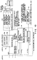
- FIG. 24 shows the twelfth embodiment of the invention, comprising a scanning unit 94 and a data-reproducing unit 96 which are connected by a cable.
- the scanning unit 94 is designed to optically read dot codes.
- the data-reproducing unit 96 is designed to process the dot code thereby to reproduce multimedia information.
- the scanning unit 94 has an error information display section 72A, which displays scanning errors and data-processing errors made in the scanning unit 94.
- the data-reproducing unit 96 has an error information display section 72B which displays errors made in the data-reproducing process performed in the data-reproducing unit 96.
- the scanning unit 94 further comprises a reading section 98 and a first hierarchial process section 100.
- the reading section 98 corresponds to the photographing-system module 32 of layer 1, which comprises a light source, an optical system, a CCD and the like.
- the first hierarchial process section 100 includes a reproduction equalizing module 34, a quantization module 36 and the like and is designed to convert dot codes read by the CCD, into binary data.
- the reading section 98 and first hierarchial process section 100 are connected by two buses and an interface (I/F).
- the first bus is a data bus to transmit the dot code data
- the second bus is a control bus to transmit error signals and control signals.
- the first hierarchial process section 100 has a binary threshold-value detecting section 102.
- the section generates a over/under-exposure signal. This signal, which indicates an error, is supplied through the control bus to the error information display section 72A. Upon receipt of the signal, the section 72A causes a red LED to emit red light, indicating a scanning error has been made.
- the data-reproducing unit 96 further comprises a data-reproducing section 104.
- the section 104 is designed to process not only the layers 2 to 5 and the application process layer.
- the section 104 has two buses, i.e., a data bus and a control bus.
- the section 104 incorporates a microcomputer 66, which controls any other component of the section 104.
- the microcomputer 66 has the error processing section 70 which processes error signals.
- the error processing section 70 supplies an error signal to the error information display section 72B.
- the section 72B displays the error represented by the error signal.
- the error signal is supplied to the error information display section 72A of the scanning unit 94, too, through the control bus and the interface (I/F).
- the section 72A display the error represented by the error signal.
- the error information display section 72A of the scanning section 94 has a green LED, besides the red LED.
- the error information display section 72B of the data-reproducing unit 96 has a liquid crystal display for displaying various messages in words and symbols.
- FIG. 25A shows items of information which are displayed by the error information display section 72A incorporated in the scanning section 94.
- the green LED is turned on.
- the red LED is turned on.
- both LED can blink.
- the green LED and the red LED can indicate nine different operating conditions of the section 96, in accordance with whether thy are turned on or off.
- FIG. 25B shows items of information which are displayed by the error information display section 72B incorporated in the data-reproducing section 96.
- the the section 72B has nine display units arranged in three rows and three columns, each for displaying a message in words or a symbol.
- the nine messages the section 72B can indicate are: (1) switch is on; (2) power supplied is sufficient; (3) the power switch is on; (4) data is being reproduced; (5) data can be read; (6) data cannot be reproduced and dot codes must be scanned again; (7) switches have been erroneously operated;, (8) codes are meaningless (OK); and (9) data can be read but cannot be reproduced.
- Each of the error information display sections 72A and 72B can display nine types of errors, some occurring in the scanning unit 94 and the others occurring in the data-reproducing unit 96. Instead, the error information display section 72A may display only errors which occur in the unit 94, while the error information display section 72B may display errors which occur in the unit 96. Needless to say, the error information display sections 72A and 72B may have means to generate sound to indicate errors occurring in the scanning unit 94 and the data-reproducing unit 96.
Landscapes
- Engineering & Computer Science (AREA)
- Signal Processing (AREA)
- Multimedia (AREA)
- Signal Processing For Digital Recording And Reproducing (AREA)
- Optical Recording Or Reproduction (AREA)
Applications Claiming Priority (2)
| Application Number | Priority Date | Filing Date | Title |
|---|---|---|---|
| JP222309/94 | 1994-09-19 | ||
| JP6222309A JPH0887577A (ja) | 1994-09-19 | 1994-09-19 | 情報記録媒体及び情報再生装置 |
Publications (2)
| Publication Number | Publication Date |
|---|---|
| EP0702369A2 true EP0702369A2 (fr) | 1996-03-20 |
| EP0702369A3 EP0702369A3 (fr) | 1999-02-24 |
Family
ID=16780345
Family Applications (1)
| Application Number | Title | Priority Date | Filing Date |
|---|---|---|---|
| EP95114567A Ceased EP0702369A3 (fr) | 1994-09-19 | 1995-09-15 | Milieu d'enregistrement d'information et dispositif de reproduction d'informations |
Country Status (3)
| Country | Link |
|---|---|
| US (3) | US5754687A (fr) |
| EP (1) | EP0702369A3 (fr) |
| JP (1) | JPH0887577A (fr) |
Cited By (2)
| Publication number | Priority date | Publication date | Assignee | Title |
|---|---|---|---|---|
| WO2003023704A1 (fr) * | 2001-09-11 | 2003-03-20 | Barrington Dyer | Enregistrement de code imprime et systeme de lecture de musique, de voix et de sons. |
| CN1308867C (zh) * | 2002-04-10 | 2007-04-04 | 汤姆森许可贸易公司 | 数据传输设备、数据接收设备及其方法 |
Families Citing this family (22)
| Publication number | Priority date | Publication date | Assignee | Title |
|---|---|---|---|---|
| JP2916373B2 (ja) * | 1994-06-02 | 1999-07-05 | オリンパス光学工業株式会社 | 情報記録媒体及び情報再生装置 |
| JPH0837567A (ja) * | 1994-07-26 | 1996-02-06 | Olympus Optical Co Ltd | 情報記録媒体及び情報再生装置 |
| JPH0887577A (ja) * | 1994-09-19 | 1996-04-02 | Olympus Optical Co Ltd | 情報記録媒体及び情報再生装置 |
| WO1996015628A1 (fr) | 1994-11-11 | 1996-05-23 | Siemens Aktiengesellschaft | Procede et dispositif pour la transmission de donnees telecopieur codees entre des terminaux de communication a capacite multimedia |
| JP2952170B2 (ja) * | 1994-12-16 | 1999-09-20 | オリンパス光学工業株式会社 | 情報再生システム |
| JP3803411B2 (ja) * | 1995-12-25 | 2006-08-02 | オリンパス株式会社 | 情報再生システム及び情報記録媒体 |
| JP2942736B2 (ja) * | 1996-09-03 | 1999-08-30 | オリンパス光学工業株式会社 | コード記録装置 |
| JPH10106166A (ja) * | 1996-09-30 | 1998-04-24 | Toshiba Corp | 再生装置と再生方法 |
| JPH10326331A (ja) * | 1997-03-24 | 1998-12-08 | Olympus Optical Co Ltd | ドットコードを有する記録媒体及びコード読取装置 |
| JP3095071B2 (ja) * | 1998-04-21 | 2000-10-03 | 日本電気株式会社 | パタンマッチング符号化装置、及びその符号化方法 |
| JPH11353420A (ja) * | 1998-06-08 | 1999-12-24 | Olympus Optical Co Ltd | コードイメージ読取装置 |
| JP4393435B2 (ja) * | 1998-11-04 | 2010-01-06 | 株式会社日立製作所 | 受信装置 |
| JP3402581B2 (ja) * | 1998-11-30 | 2003-05-06 | 日本ビクター株式会社 | データ復元装置 |
| US6122230A (en) * | 1999-02-09 | 2000-09-19 | Advanced Communication Design, Inc. | Universal compressed audio player |
| JP4749522B2 (ja) * | 1999-03-26 | 2011-08-17 | ソニー株式会社 | 再生装置および再生方法 |
| WO2001033488A1 (fr) * | 1999-11-02 | 2001-05-10 | Omron Corporation | Code par points bidimensionnel |
| JP4763905B2 (ja) * | 2001-03-06 | 2011-08-31 | オリンパス株式会社 | 符号化画像読取装置 |
| JP2003203349A (ja) * | 2001-10-26 | 2003-07-18 | Shinano Kenshi Co Ltd | 光ディスク記録再生装置 |
| US7169996B2 (en) * | 2002-11-12 | 2007-01-30 | Medialab Solutions Llc | Systems and methods for generating music using data/music data file transmitted/received via a network |
| JP4209176B2 (ja) * | 2002-11-14 | 2009-01-14 | アルパイン株式会社 | クライアント装置およびサーバ装置 |
| JP2012060461A (ja) * | 2010-09-09 | 2012-03-22 | Sony Corp | 再生装置、再生方法、及びプログラム |
| US20130279882A1 (en) * | 2012-04-23 | 2013-10-24 | Apple Inc. | Coding of Video and Audio with Initialization Fragments |
Citations (3)
| Publication number | Priority date | Publication date | Assignee | Title |
|---|---|---|---|---|
| JPH0581673A (ja) * | 1991-09-20 | 1993-04-02 | Csk Corp | リーダーライタ装置及び挿入エラー識別方式 |
| WO1994008314A1 (fr) | 1992-09-28 | 1994-04-14 | Olympus Optical Co., Ltd. | Code a points et systeme d'enregistrement/de reproduction de donnees permettant l'enregistrement/la reproduction d'un code a points |
| JPH06121368A (ja) | 1992-10-08 | 1994-04-28 | N T T Idou Tsuushinmou Kk | 移動通信加入者データアクセス方式 |
Family Cites Families (13)
| Publication number | Priority date | Publication date | Assignee | Title |
|---|---|---|---|---|
| DK127080C (da) * | 1967-07-07 | 1974-03-04 | Svejsecentralen | Fremgangsmåde til automatisk sortering eller registrering af genstande, der hver især er forsynet med en visuel, kodet information, samt et anlæg til udøvelse af fremgangsmåden. |
| WO1980000200A1 (fr) * | 1978-07-07 | 1980-02-07 | News Log Int Inc | Systeme de controle d'information sur microfiche |
| JPS6253750U (fr) * | 1985-09-20 | 1987-04-03 | ||
| JPS62289936A (ja) * | 1986-06-07 | 1987-12-16 | Omron Tateisi Electronics Co | 光学メモリ応用装置 |
| JPH02105333A (ja) * | 1988-10-14 | 1990-04-17 | Hitachi Ltd | 光記録シートならびにその再生方法および再生装置 |
| JPH02244293A (ja) * | 1989-03-17 | 1990-09-28 | Hitachi Ltd | 情報メデイア |
| JP3356442B2 (ja) * | 1991-06-04 | 2002-12-16 | 株式会社東芝 | データ記録再生装置 |
| US5357281A (en) * | 1991-11-07 | 1994-10-18 | Canon Kabushiki Kaisha | Image processing apparatus and terminal apparatus |
| JP2833975B2 (ja) * | 1992-09-28 | 1998-12-09 | オリンパス光学工業株式会社 | ドットコード |
| CA2107727C (fr) * | 1992-10-07 | 1999-06-01 | Hiroaki Ueda | Systeme de compression synchrone et de reconstruction de donnees video et audio |
| JP2916373B2 (ja) * | 1994-06-02 | 1999-07-05 | オリンパス光学工業株式会社 | 情報記録媒体及び情報再生装置 |
| JPH0837567A (ja) * | 1994-07-26 | 1996-02-06 | Olympus Optical Co Ltd | 情報記録媒体及び情報再生装置 |
| JPH0887577A (ja) * | 1994-09-19 | 1996-04-02 | Olympus Optical Co Ltd | 情報記録媒体及び情報再生装置 |
-
1994
- 1994-09-19 JP JP6222309A patent/JPH0887577A/ja active Pending
-
1995
- 1995-09-13 US US08/527,405 patent/US5754687A/en not_active Expired - Fee Related
- 1995-09-15 EP EP95114567A patent/EP0702369A3/fr not_active Ceased
-
1998
- 1998-02-12 US US09/022,872 patent/US5999665A/en not_active Expired - Fee Related
-
1999
- 1999-10-04 US US09/411,089 patent/US6148121A/en not_active Expired - Fee Related
Patent Citations (3)
| Publication number | Priority date | Publication date | Assignee | Title |
|---|---|---|---|---|
| JPH0581673A (ja) * | 1991-09-20 | 1993-04-02 | Csk Corp | リーダーライタ装置及び挿入エラー識別方式 |
| WO1994008314A1 (fr) | 1992-09-28 | 1994-04-14 | Olympus Optical Co., Ltd. | Code a points et systeme d'enregistrement/de reproduction de donnees permettant l'enregistrement/la reproduction d'un code a points |
| JPH06121368A (ja) | 1992-10-08 | 1994-04-28 | N T T Idou Tsuushinmou Kk | 移動通信加入者データアクセス方式 |
Non-Patent Citations (1)
| Title |
|---|
| PATENT ABSTRACTS OF JAPAN vol. 017, no. 422 (P - 1586) 5 August 1993 (1993-08-05) * |
Cited By (2)
| Publication number | Priority date | Publication date | Assignee | Title |
|---|---|---|---|---|
| WO2003023704A1 (fr) * | 2001-09-11 | 2003-03-20 | Barrington Dyer | Enregistrement de code imprime et systeme de lecture de musique, de voix et de sons. |
| CN1308867C (zh) * | 2002-04-10 | 2007-04-04 | 汤姆森许可贸易公司 | 数据传输设备、数据接收设备及其方法 |
Also Published As
| Publication number | Publication date |
|---|---|
| US6148121A (en) | 2000-11-14 |
| US5754687A (en) | 1998-05-19 |
| EP0702369A3 (fr) | 1999-02-24 |
| JPH0887577A (ja) | 1996-04-02 |
| US5999665A (en) | 1999-12-07 |
Similar Documents
| Publication | Publication Date | Title |
|---|---|---|
| US5754687A (en) | Information recording medium and information reproducing apparatus capable of stably reproducing changeable code patterns at high speed | |
| EP0703580B1 (fr) | Dispositif de reproduction d'information | |
| EP1383107B1 (fr) | Structure de code de sonnerie et appareil de lecture de code de sonnerie pour téléphone cellulaire | |
| CN100471242C (zh) | 编码/解码字幕数据项的方法和设备 | |
| EP0720347B1 (fr) | Système pour le codage/décodage d'information d'images | |
| US5841793A (en) | Optical reproduction system having function of rationally changing error data chunk and reproducing multimedia information as code data | |
| CN1781149A (zh) | 具有用于管理文本字幕数据重现的数据结构的记录媒体以及记录和重现的方法和装置 | |
| JPH0837567A (ja) | 情報記録媒体及び情報再生装置 | |
| US5719886A (en) | System for optically recording/reproducing multimedia information using code data | |
| CN1130905C (zh) | 产生数字视频图像的设备 | |
| JPH06314092A (ja) | 文字画像用記録再生装置 | |
| CN1081380C (zh) | 数据再现设备 | |
| EP0961505A2 (fr) | Appareil et procédé de codage d'image supplémentaire | |
| JP2000032388A (ja) | ビデオ及び/又はオ―ディオ信号の記録及び再生用の方法並びに装置 | |
| KR940003668B1 (ko) | 복호신호 에러 수정장치 | |
| JP3660416B2 (ja) | 画像データのエンコード/デコードシステム | |
| JP2002140196A (ja) | 情報再生装置及び情報記録媒体 | |
| JP2000067191A (ja) | カラーバーコードの生成方法及び装置並びに再生方法及び装置 | |
| JP3430489B2 (ja) | インデックスエリアに文字情報を記録するビデオテープレコーダの記録方法 | |
| JP2000209588A (ja) | 画像の符号化方法及び復号方法、電子装置のための副映像デ―タユニットの構成方法、電子装置、及び、電子装置で使用されるデ―タ担体 | |
| JP2857427B2 (ja) | 情報データ処理装置 | |
| GB2379824A (en) | Displaying still images on a divided screen | |
| JP2004186808A (ja) | エンコード方法とデコード方法、及びこれらの装置と記録媒体 | |
| JP3500367B2 (ja) | 情報再生装置 | |
| JPH08146980A (ja) | カラオケシステム |
Legal Events
| Date | Code | Title | Description |
|---|---|---|---|
| PUAI | Public reference made under article 153(3) epc to a published international application that has entered the european phase |
Free format text: ORIGINAL CODE: 0009012 |
|
| AK | Designated contracting states |
Kind code of ref document: A2 Designated state(s): AT BE CH DE DK ES FR GB GR IE IT LI LU MC NL PT SE |
|
| PUAL | Search report despatched |
Free format text: ORIGINAL CODE: 0009013 |
|
| AK | Designated contracting states |
Kind code of ref document: A3 Designated state(s): AT BE CH DE DK ES FR GB GR IE IT LI LU MC NL PT SE |
|
| 17P | Request for examination filed |
Effective date: 19990204 |
|
| 17Q | First examination report despatched |
Effective date: 20000403 |
|
| RTI1 | Title (correction) |
Free format text: INFORMATION REPRODUCING DEVICE |
|
| GRAG | Despatch of communication of intention to grant |
Free format text: ORIGINAL CODE: EPIDOS AGRA |
|
| STAA | Information on the status of an ep patent application or granted ep patent |
Free format text: STATUS: THE APPLICATION HAS BEEN REFUSED |
|
| 18R | Application refused |
Effective date: 20020131 |