EP0702405A1 - Eine pneumatisch gekoppelte Wärmesenkemontage - Google Patents
Eine pneumatisch gekoppelte Wärmesenkemontage Download PDFInfo
- Publication number
- EP0702405A1 EP0702405A1 EP95114226A EP95114226A EP0702405A1 EP 0702405 A1 EP0702405 A1 EP 0702405A1 EP 95114226 A EP95114226 A EP 95114226A EP 95114226 A EP95114226 A EP 95114226A EP 0702405 A1 EP0702405 A1 EP 0702405A1
- Authority
- EP
- European Patent Office
- Prior art keywords
- heat sink
- heat
- pneumatic
- pneumatic pathways
- air flow
- Prior art date
- Legal status (The legal status is an assumption and is not a legal conclusion. Google has not performed a legal analysis and makes no representation as to the accuracy of the status listed.)
- Granted
Links
Images

Classifications
-
- H—ELECTRICITY
- H10—SEMICONDUCTOR DEVICES; ELECTRIC SOLID-STATE DEVICES NOT OTHERWISE PROVIDED FOR
- H10W—GENERIC PACKAGES, INTERCONNECTIONS, CONNECTORS OR OTHER CONSTRUCTIONAL DETAILS OF DEVICES COVERED BY CLASS H10
- H10W40/00—Arrangements for thermal protection or thermal control
- H10W40/40—Arrangements for thermal protection or thermal control involving heat exchange by flowing fluids
- H10W40/43—Arrangements for thermal protection or thermal control involving heat exchange by flowing fluids by flowing gases, e.g. forced air cooling
Definitions
- This invention relates generally to heat sinks and, in particular, to heat sinks used in communication equipment.
- Radio communication systems that provide cellular and land mobile communication services are known in the art.
- Such systems comprise infrastructure equipment, which includes equipment located at one or more sites, and subscriber units, which include portable and mobile communication units.
- infrastructure equipment which includes equipment located at one or more sites, and subscriber units, which include portable and mobile communication units.
- subscriber units which include portable and mobile communication units.
- a variety of equipment is required at each site.
- Such equipment includes radio base stations that support communication channels.
- a base station includes a receiver and a transmitter, where the transmitter amplifies the signal before transmission. This amplification generates a significant amount of heat during operation due to the internal components of the transmitter. In many cases, if left uncontrolled, the heat generated can permanently damage these internal components.
- forced air cooling where the heat generating devices of the transmitter are mounted on a heat sink that comprises a mass of thermally conductive material, such as aluminum.
- the forced air is provided by a fan located adjacent to the heat sink.
- the heat generated by the device is conducted to the heat sink, where the air flow from the fan dissipates the heat to the ambient air.
- Relative to other methods of cooling, such as liquid cooling, forced air cooling offers an economical solution that is relatively easy to incorporate in the design and manufacture of a base station.
- FIG. 1 illustrates an isometric view of a heat sink assembly in accordance with the present invention.
- FIG. 2 illustrates a view of the air flow from an air circulator in accordance with the present invention.
- FIG. 3 illustrates a view of the air flow from an adjacent heat sink in accordance with the present invention.
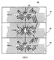
- FIG. 4 illustrates a view of the air flow within three adjacent heat sinks in accordance with the present invention.
- the present invention provides a pneumatically coupled heat sink assembly that allows greater heat dissipation when multiple heat sinks are juxtaposed. This is accomplished through the use of pneumatic pathways being operably coupled with the pneumatic pathways of adjacent heat sinks. These pneumatic pathways are made through heat radiating surfaces that will have at least two of the pneumatic pathways being non-parallel. The non-parallel pneumatic pathways provide the ability for the air flow to be directed away from the air circulator toward the periphery of the heat sink. This allows the air to be then transferred to an adjacent heat sink that can assist in dissipating the heat.
- FIG. 1 illustrates an isometric view of a heat sink assembly 100.
- Air flow 101 represents a forced air flow from an air circulator, which in a preferred embodiment is a fan, mounted to heat sink 100.
- the fan generates a first air flow 101, which flows substantially perpendicular to the convective surface.
- air flow 101 is directed towards heat sink 100, it is directed into the air flow paths 102.
- the air flow paths 102 are pneumatic pathways which run substantially parallel to the convective surface and are directed through the heat radiating surfaces toward the periphery of the heat sink 100. The air flow can then be dissipated to the ambient air or pneumatically passed to an adjacent heat sink, as later described.
- FIG. 2 illustrates a view of the forced air flow through heat sink assembly 200.
- Pneumatic pathways 201 are formed throughout the heat sink assembly by heat radiating surfaces, such as heat fins.
- Air flow 202 represents air flow that has been directed from the area of the air circulator towards the periphery of heat sink 200 through pneumatic pathway 201. This air flow could then be passed to an adjacent heat sink, such as the heat sink represented in FIG. 3.
- FIG. 3 illustrates a view of air flow through heat sink assembly 300.
- pneumatic pathways 201 are formed between heat radiating surfaces of the heat sink.
- Air flows 302 are air flows that could originate from an adjacent heat sink.
- Air flow 301 represents the air flow through heat sink 300, away from the periphery of the convective base surface. These air flows 301 are then dispersed throughout other pneumatic pathways of the heat sink 300 via, e.g., traversing pneumatic pathways 303, as shown. In this manner, the air is permitted to flow throughout the heat radiating surfaces of the heat sink for improved heat dissipation.
- FIG. 4 shows a heat sink assembly 400 that includes three heat sinks (401, 402, and 403) arranged in a pattern according to the present invention.
- heat sinks 401 and 403 include air circulators that force air through the heat radiating surfaces of the heat sinks toward the periphery of the heat sinks.
- Heat sink 402 represents a heat sink without an air circulator. Heat sink 402 will receive air flow from the periphery of heat sinks 401 and 403, and this air flow will be dispersed among the pneumatic pathways formed among the heat radiating surfaces of heat sink 402. The pneumatic pathways of the adjacent heat sinks are aligned such that they will be pneumatically coupled to produce an increased ability to dissipate heat.
- the heat sinks will be aligned so as to minimize the restriction of air flow between adjacent heat sinks.
- the adjacent heat sinks do not need to be perfectly aligned to produce an increased degree of heat dissipation.
- at least two of the pneumatic pathways are at least partially pneumatically coupled, there will be an increase in the heat dissipative ability of the heat sink assembly.
- the present invention provides an increased ability to dissipate heat by juxtaposing multiple heat sinks.
- the heat sinks can include air circulators, such as fans, or they can dissipate heat into the ambient air, as is known in the art. They can also dissipate the heat generated by adjacent heat sinks and passed through pneumatic pathways that couple the heat sinks.
- a heat sink assembly in accordance with the present invention is economical to manufacture and capable of providing greater heat dissipation without the disadvantages that are associated with large heat sinks.
- the present invention will be more economical to manufacture and will provide greater heat dissipation, along with providing the ability to increase the heat dissipation of a heat sink assembly without having to replace a smaller heat sink with a larger heat sink.
- the present invention also allows the flexibility to use multiple heat sinks where currently only large, less economical heat sinks can be used.
Landscapes
- Cooling Or The Like Of Electrical Apparatus (AREA)
- Cooling Or The Like Of Semiconductors Or Solid State Devices (AREA)
Applications Claiming Priority (2)
| Application Number | Priority Date | Filing Date | Title |
|---|---|---|---|
| US308316 | 1994-09-19 | ||
| US08/308,316 US5582240A (en) | 1994-09-19 | 1994-09-19 | Pneumatically coupled heat sink assembly |
Publications (2)
| Publication Number | Publication Date |
|---|---|
| EP0702405A1 true EP0702405A1 (de) | 1996-03-20 |
| EP0702405B1 EP0702405B1 (de) | 2003-05-14 |
Family
ID=23193489
Family Applications (1)
| Application Number | Title | Priority Date | Filing Date |
|---|---|---|---|
| EP95114226A Expired - Lifetime EP0702405B1 (de) | 1994-09-19 | 1995-09-11 | Eine pneumatisch gekoppelte Wärmesenkemontage |
Country Status (10)
| Country | Link |
|---|---|
| US (1) | US5582240A (de) |
| EP (1) | EP0702405B1 (de) |
| KR (1) | KR0182794B1 (de) |
| CN (1) | CN1082724C (de) |
| BR (1) | BR9504030A (de) |
| CO (1) | CO4370140A1 (de) |
| DE (1) | DE69530732T2 (de) |
| NZ (1) | NZ280015A (de) |
| TW (1) | TW307070B (de) |
| ZA (1) | ZA957902B (de) |
Cited By (5)
| Publication number | Priority date | Publication date | Assignee | Title |
|---|---|---|---|---|
| EP0933878A1 (de) * | 1998-01-27 | 1999-08-04 | Lucent Technologies Inc. | Kühlsystem eines Funkkommunikationsgerät |
| EP1202346A1 (de) * | 2000-09-29 | 2002-05-02 | Siemens Aktiengesellschaft | Wärmesenke |
| WO2003030608A1 (en) * | 2001-10-04 | 2003-04-10 | Celestica International Inc. | Cooling system having independent fan location |
| EP1526570A3 (de) * | 2003-10-22 | 2005-06-15 | Motorola, Inc. | Wärmesenken |
| US6912128B2 (en) | 2001-08-09 | 2005-06-28 | Celestica International Inc. | Electronics cooling subassembly |
Families Citing this family (31)
| Publication number | Priority date | Publication date | Assignee | Title |
|---|---|---|---|---|
| US5785116A (en) * | 1996-02-01 | 1998-07-28 | Hewlett-Packard Company | Fan assisted heat sink device |
| JPH11121667A (ja) * | 1997-10-20 | 1999-04-30 | Fujitsu Ltd | ヒートパイプ式冷却装置 |
| US5927385A (en) * | 1998-01-21 | 1999-07-27 | Yeh; Ming Hsin | Cooling device for the CPU of computer |
| US6176299B1 (en) | 1999-02-22 | 2001-01-23 | Agilent Technologies, Inc. | Cooling apparatus for electronic devices |
| US6199624B1 (en) * | 1999-04-30 | 2001-03-13 | Molex Incorporated | Folded fin heat sink and a heat exchanger employing the heat sink |
| US6360816B1 (en) | 1999-12-23 | 2002-03-26 | Agilent Technologies, Inc. | Cooling apparatus for electronic devices |
| US6418020B1 (en) * | 2001-03-30 | 2002-07-09 | Advanced Thermal Technologies | Heat dissipation device with ribbed fin plates |
| US8505063B2 (en) * | 2002-02-22 | 2013-08-06 | Qwest Communications International Inc. | Systems and methods for providing redundant back-up to a video transmission system |
| US6972950B1 (en) * | 2002-06-06 | 2005-12-06 | Raytheon Company | Method and apparatus for cooling a portable computer |
| US7046515B1 (en) | 2002-06-06 | 2006-05-16 | Raytheon Company | Method and apparatus for cooling a circuit component |
| DE10234500A1 (de) * | 2002-07-23 | 2004-02-19 | Siemens Ag | Verfahren zur Wärmeableitung in Mobilfunkgeräten und ein entsprechendes Mobilfunkgerät |
| US6735082B2 (en) * | 2002-08-14 | 2004-05-11 | Agilent Technologies, Inc. | Heatsink with improved heat dissipation capability |
| US20040163795A1 (en) * | 2003-02-25 | 2004-08-26 | Yi-Yung Lin | Heat sink |
| US7079390B2 (en) * | 2003-06-05 | 2006-07-18 | Hewlett-Packard Development, L.P. | System and method for heat dissipation and air flow redirection in a chassis |
| US7198094B2 (en) * | 2003-06-20 | 2007-04-03 | Hewlett-Packard Development Company, L.P. | Finned device for removing heat from an electronic component |
| CN2672865Y (zh) * | 2003-11-14 | 2005-01-19 | 鸿富锦精密工业(深圳)有限公司 | 散热器 |
| US6958914B2 (en) * | 2003-12-09 | 2005-10-25 | Dell Products L.P. | Interlocking heat sink |
| TWI251460B (en) * | 2004-01-09 | 2006-03-11 | Delta Electronics Inc | Compound heat sink with multi-directional fins |
| US7779648B2 (en) * | 2004-11-01 | 2010-08-24 | Tecumseh Products Company | Heat exchanger with enhanced air distribution |
| KR100719702B1 (ko) * | 2005-05-25 | 2007-05-17 | 삼성에스디아이 주식회사 | 플라즈마 디스플레이 장치 |
| JP4480638B2 (ja) * | 2005-07-04 | 2010-06-16 | Necディスプレイソリューションズ株式会社 | 貫流型強制空冷ヒートシンクおよび投写型表示装置 |
| US7532476B2 (en) * | 2006-06-29 | 2009-05-12 | Intel Corporation | Flow solutions for microelectronic cooling |
| CN101516713A (zh) * | 2006-09-19 | 2009-08-26 | 三菱电机株式会社 | 移动体用冷却装置 |
| USD613258S1 (en) * | 2009-05-15 | 2010-04-06 | Koninklije Philips Electronics N.V. | Heatsink |
| USD638376S1 (en) * | 2010-08-06 | 2011-05-24 | Cisco Technology, Inc. | Passive cooling element |
| USD644615S1 (en) * | 2010-08-31 | 2011-09-06 | Canon U.S. Life Sciences, Inc. | Two part heat spreader |
| US20130014921A1 (en) * | 2011-07-14 | 2013-01-17 | Chen Chih-Peng | Air flow guiding structure |
| WO2015022032A1 (en) * | 2013-08-16 | 2015-02-19 | Huawei Technologies Co., Ltd. | Enhanced structure for natural cooling heat sink |
| KR20150145084A (ko) * | 2014-06-18 | 2015-12-29 | 주식회사 케이엠더블유 | 방열 장치 |
| CA2995090A1 (en) | 2015-08-07 | 2017-02-16 | Vishay Dale Electronics, Llc | Molded body and electrical device having a molded body for high voltage applications |
| US11067963B2 (en) * | 2019-01-09 | 2021-07-20 | Dell Products L.P. | System and method for thermal management in a multicomponent system |
Citations (2)
| Publication number | Priority date | Publication date | Assignee | Title |
|---|---|---|---|---|
| US4753290A (en) * | 1986-07-18 | 1988-06-28 | Unisys Corporation | Reduced-stress heat sink device |
| US5019880A (en) * | 1988-01-07 | 1991-05-28 | Prime Computer, Inc. | Heat sink apparatus |
Family Cites Families (16)
| Publication number | Priority date | Publication date | Assignee | Title |
|---|---|---|---|---|
| BE527420A (de) * | 1953-03-20 | |||
| US2965819A (en) * | 1958-08-07 | 1960-12-20 | Rosenbaum Jacob | Heat dissipating electronic mounting apparatus |
| GB1054001A (de) * | 1964-02-14 | |||
| US3280907A (en) * | 1964-09-01 | 1966-10-25 | Hoffman Sidney | Energy transfer device |
| US3312277A (en) * | 1965-03-22 | 1967-04-04 | Astrodyne Inc | Heat sink |
| US3592260A (en) * | 1969-12-05 | 1971-07-13 | Espey Mfg & Electronics Corp | Heat exchanger with inner guide strip |
| US3955122A (en) * | 1974-02-26 | 1976-05-04 | Armor Elevator Company, Inc. | Heat sink mounting for controlled rectifiers |
| US4823869A (en) * | 1986-06-19 | 1989-04-25 | International Business Machines Corporation | Heat sink |
| US4682651A (en) * | 1986-09-08 | 1987-07-28 | Burroughs Corporation (Now Unisys Corporation) | Segmented heat sink device |
| US5077601A (en) * | 1988-09-09 | 1991-12-31 | Hitachi, Ltd. | Cooling system for cooling an electronic device and heat radiation fin for use in the cooling system |
| JPH03222350A (ja) * | 1990-01-29 | 1991-10-01 | Hitachi Ltd | 樹脂封止形半導体装置及びその実装構造 |
| JP2544497B2 (ja) * | 1990-02-28 | 1996-10-16 | 株式会社日立製作所 | コンピュ―タ冷却装置 |
| JPH04192552A (ja) * | 1990-11-27 | 1992-07-10 | Nec Corp | 半導体素子用パッケージ |
| JPH0548282A (ja) * | 1991-08-19 | 1993-02-26 | Sansha Electric Mfg Co Ltd | 冷却フイン構造 |
| US5329436A (en) * | 1993-10-04 | 1994-07-12 | David Chiu | Removable heat sink for xenon arc lamp packages |
| US5368094A (en) * | 1993-11-02 | 1994-11-29 | Hung; Chin-Ping | Bipartite heat sink positioning device for computer chips |
-
1994
- 1994-09-19 US US08/308,316 patent/US5582240A/en not_active Expired - Lifetime
-
1995
- 1995-08-02 TW TW084108017A patent/TW307070B/zh active
- 1995-09-11 EP EP95114226A patent/EP0702405B1/de not_active Expired - Lifetime
- 1995-09-11 DE DE69530732T patent/DE69530732T2/de not_active Expired - Fee Related
- 1995-09-14 NZ NZ280015A patent/NZ280015A/en unknown
- 1995-09-15 BR BR9504030A patent/BR9504030A/pt not_active IP Right Cessation
- 1995-09-18 CN CN95116288A patent/CN1082724C/zh not_active Expired - Fee Related
- 1995-09-18 KR KR1019950030406A patent/KR0182794B1/ko not_active Expired - Fee Related
- 1995-09-19 ZA ZA957902A patent/ZA957902B/xx unknown
- 1995-09-19 CO CO95042912A patent/CO4370140A1/es unknown
Patent Citations (2)
| Publication number | Priority date | Publication date | Assignee | Title |
|---|---|---|---|---|
| US4753290A (en) * | 1986-07-18 | 1988-06-28 | Unisys Corporation | Reduced-stress heat sink device |
| US5019880A (en) * | 1988-01-07 | 1991-05-28 | Prime Computer, Inc. | Heat sink apparatus |
Cited By (5)
| Publication number | Priority date | Publication date | Assignee | Title |
|---|---|---|---|---|
| EP0933878A1 (de) * | 1998-01-27 | 1999-08-04 | Lucent Technologies Inc. | Kühlsystem eines Funkkommunikationsgerät |
| EP1202346A1 (de) * | 2000-09-29 | 2002-05-02 | Siemens Aktiengesellschaft | Wärmesenke |
| US6912128B2 (en) | 2001-08-09 | 2005-06-28 | Celestica International Inc. | Electronics cooling subassembly |
| WO2003030608A1 (en) * | 2001-10-04 | 2003-04-10 | Celestica International Inc. | Cooling system having independent fan location |
| EP1526570A3 (de) * | 2003-10-22 | 2005-06-15 | Motorola, Inc. | Wärmesenken |
Also Published As
| Publication number | Publication date |
|---|---|
| CN1125319A (zh) | 1996-06-26 |
| NZ280015A (en) | 1997-07-27 |
| TW307070B (de) | 1997-06-01 |
| CO4370140A1 (es) | 1996-10-07 |
| ZA957902B (en) | 1996-04-29 |
| DE69530732D1 (de) | 2003-06-18 |
| CN1082724C (zh) | 2002-04-10 |
| DE69530732T2 (de) | 2003-12-18 |
| US5582240A (en) | 1996-12-10 |
| KR960013151A (ko) | 1996-04-20 |
| EP0702405B1 (de) | 2003-05-14 |
| BR9504030A (pt) | 1996-09-24 |
| KR0182794B1 (ko) | 1999-03-20 |
Similar Documents
| Publication | Publication Date | Title |
|---|---|---|
| US5582240A (en) | Pneumatically coupled heat sink assembly | |
| US6330153B1 (en) | Method and system for efficiently removing heat generated from an electronic device | |
| US6851467B1 (en) | Heat sink assembly | |
| EP3440906B1 (de) | Systeme und verfahren zur wärmeverwaltung für emv-abgeschirmte elektronische vorrichtungen mit hoher leistungsdichte | |
| US6691768B2 (en) | Heatsink design for uniform heat dissipation | |
| EP3222955B1 (de) | Kühlvorrichtung und projektionsanzeigevorrichtung | |
| CN108064430B (zh) | 可旋转天线设备 | |
| US6667883B1 (en) | Forced-air cooling of a transceiver unit | |
| CA2261554A1 (en) | Electronic apparatus having an environmentally sealed external enclosure | |
| JP2004228484A (ja) | 冷却装置及び電子機器 | |
| CN107210512B (zh) | 无线电单元壳体和基站天线模块 | |
| US6845812B2 (en) | Heatsink with multiple, selectable fin densities | |
| KR20190065816A (ko) | 엠아이엠오 안테나 장치 | |
| US20230139054A1 (en) | Thermal-Control System Of A Mesh Network Device and Associated Mesh Network Devices | |
| EP2383779B1 (de) | Montagebasis | |
| US6965515B2 (en) | Thermoelectric cooling of low-noise amplifier transistors in wireless communications networks | |
| KR100939992B1 (ko) | 전기전자기기의 냉각장치 및 이를 장착한 전기전자기기 | |
| EP1440612B1 (de) | Mobil-satellitenstreckenendgerät | |
| US11605886B1 (en) | Radome with integrated passive cooling | |
| US6515859B2 (en) | Heat sink alignment | |
| JPH10270616A (ja) | 電子部品の放熱装置 | |
| US20040070939A1 (en) | Heat sink system | |
| US6873527B2 (en) | Heat transfer apparatus | |
| US6452799B1 (en) | Integrated circuit cooling system | |
| CN110602925A (zh) | 一种散热件、通信散热系统 |
Legal Events
| Date | Code | Title | Description |
|---|---|---|---|
| PUAI | Public reference made under article 153(3) epc to a published international application that has entered the european phase |
Free format text: ORIGINAL CODE: 0009012 |
|
| AK | Designated contracting states |
Kind code of ref document: A1 Designated state(s): DE FR GB |
|
| 17P | Request for examination filed |
Effective date: 19960920 |
|
| 17Q | First examination report despatched |
Effective date: 19971015 |
|
| GRAH | Despatch of communication of intention to grant a patent |
Free format text: ORIGINAL CODE: EPIDOS IGRA |
|
| GRAH | Despatch of communication of intention to grant a patent |
Free format text: ORIGINAL CODE: EPIDOS IGRA |
|
| GRAA | (expected) grant |
Free format text: ORIGINAL CODE: 0009210 |
|
| AK | Designated contracting states |
Designated state(s): DE FR GB |
|
| REG | Reference to a national code |
Ref country code: GB Ref legal event code: FG4D |
|
| REF | Corresponds to: |
Ref document number: 69530732 Country of ref document: DE Date of ref document: 20030618 Kind code of ref document: P |
|
| ET | Fr: translation filed | ||
| PLBE | No opposition filed within time limit |
Free format text: ORIGINAL CODE: 0009261 |
|
| STAA | Information on the status of an ep patent application or granted ep patent |
Free format text: STATUS: NO OPPOSITION FILED WITHIN TIME LIMIT |
|
| 26N | No opposition filed |
Effective date: 20040217 |
|
| PGFP | Annual fee paid to national office [announced via postgrant information from national office to epo] |
Ref country code: GB Payment date: 20040812 Year of fee payment: 10 |
|
| PGFP | Annual fee paid to national office [announced via postgrant information from national office to epo] |
Ref country code: FR Payment date: 20040902 Year of fee payment: 10 |
|
| PGFP | Annual fee paid to national office [announced via postgrant information from national office to epo] |
Ref country code: DE Payment date: 20040930 Year of fee payment: 10 |
|
| PG25 | Lapsed in a contracting state [announced via postgrant information from national office to epo] |
Ref country code: GB Free format text: LAPSE BECAUSE OF NON-PAYMENT OF DUE FEES Effective date: 20050911 |
|
| PG25 | Lapsed in a contracting state [announced via postgrant information from national office to epo] |
Ref country code: DE Free format text: LAPSE BECAUSE OF NON-PAYMENT OF DUE FEES Effective date: 20060401 |
|
| GBPC | Gb: european patent ceased through non-payment of renewal fee |
Effective date: 20050911 |
|
| PG25 | Lapsed in a contracting state [announced via postgrant information from national office to epo] |
Ref country code: FR Free format text: LAPSE BECAUSE OF NON-PAYMENT OF DUE FEES Effective date: 20060531 |
|
| REG | Reference to a national code |
Ref country code: FR Ref legal event code: ST Effective date: 20060531 |