EP0702430A2 - Elektrischer Verbinder mit polarisierten Anschlussbuchsen - Google Patents
Elektrischer Verbinder mit polarisierten Anschlussbuchsen Download PDFInfo
- Publication number
- EP0702430A2 EP0702430A2 EP95114234A EP95114234A EP0702430A2 EP 0702430 A2 EP0702430 A2 EP 0702430A2 EP 95114234 A EP95114234 A EP 95114234A EP 95114234 A EP95114234 A EP 95114234A EP 0702430 A2 EP0702430 A2 EP 0702430A2
- Authority
- EP
- European Patent Office
- Prior art keywords
- terminal
- polarizing
- extension
- cavities
- extensions
- Prior art date
- Legal status (The legal status is an assumption and is not a legal conclusion. Google has not performed a legal analysis and makes no representation as to the accuracy of the status listed.)
- Granted
Links
Images




Classifications
-
- H—ELECTRICITY
- H01—ELECTRIC ELEMENTS
- H01R—ELECTRICALLY-CONDUCTIVE CONNECTIONS; STRUCTURAL ASSOCIATIONS OF A PLURALITY OF MUTUALLY-INSULATED ELECTRICAL CONNECTING ELEMENTS; COUPLING DEVICES; CURRENT COLLECTORS
- H01R43/00—Apparatus or processes specially adapted for manufacturing, assembling, maintaining, or repairing of line connectors or current collectors or for joining electric conductors
- H01R43/20—Apparatus or processes specially adapted for manufacturing, assembling, maintaining, or repairing of line connectors or current collectors or for joining electric conductors for assembling or disassembling contact members with insulating base, case or sleeve
-
- H—ELECTRICITY
- H01—ELECTRIC ELEMENTS
- H01R—ELECTRICALLY-CONDUCTIVE CONNECTIONS; STRUCTURAL ASSOCIATIONS OF A PLURALITY OF MUTUALLY-INSULATED ELECTRICAL CONNECTING ELEMENTS; COUPLING DEVICES; CURRENT COLLECTORS
- H01R13/00—Details of coupling devices of the kinds covered by groups H01R12/70 or H01R24/00 - H01R33/00
- H01R13/02—Contact members
- H01R13/15—Pins, blades or sockets having separate spring member for producing or increasing contact pressure
- H01R13/18—Pins, blades or sockets having separate spring member for producing or increasing contact pressure with the spring member surrounding the socket
-
- H—ELECTRICITY
- H01—ELECTRIC ELEMENTS
- H01R—ELECTRICALLY-CONDUCTIVE CONNECTIONS; STRUCTURAL ASSOCIATIONS OF A PLURALITY OF MUTUALLY-INSULATED ELECTRICAL CONNECTING ELEMENTS; COUPLING DEVICES; CURRENT COLLECTORS
- H01R13/00—Details of coupling devices of the kinds covered by groups H01R12/70 or H01R24/00 - H01R33/00
- H01R13/40—Securing contact members in or to a base or case; Insulating of contact members
Definitions
- This invention relates to an electrical connector having electrical terminals therein that are polarized with respect to the housing of the connector.
- Many electrical connectors typically comprise an insulative housing having a plurality of cavities extending therethrough, in which are inserted electrical terminals having a connection end on one end for connection to conducting wires, and a complementary terminal mating end at the other end of the terminal.
- Some terminals in particular small terminals for high density packing in an electrical connector, have roughly square or axi-symmetric shapes.
- the walls separating the terminals become rather thin and therefore quite flexible. Due to the latter two points, it has been possible in certain prior art designs to mistakenly insert the terminals with the wrong orientation within their corresponding cavities.
- Such terminals are not necessarily perfectly square in profile, the thin connector walls are flexible and sometimes allow insertion of the terminal with a 90° orientation with respect to it's intended orientation.
- Such terminals may comprise a pair of opposed cantilever beam contact for mating to a complementary tab contact, such contacts therefore being unmatable to the male tab contact when orientated about their axis by 90° with respect to their correct coupling orientation.
- Such terminals however are matable even if orientated 180° as the cantilever beam contacts are thus once again aligned with the plane of the mating tab contact.
- An object of this invention has been achieved by providing a connector comprising a stamped and formed electrical terminal having a U-shaped base portion extending between a connection section for connecting to conducting wires, and a mating section for electrical connection to a complementary terminal, whereby a side wall of the U-shaped base section extends upwards beyond a tip of an opposing side wall of the base section, and the opposing side wall has an extension directed downwards beyond a base wall of the U-shaped base section such that the terminal can be mounted in a cavity of an electrical connector in a first orientation or in a second orientation 180° with respect thereto, but not at 90° with respect thereto, the connector having grooves therein to accommodate the side wall extensions.
- the diagonally opposed polarizing extensions allow for a more compact configuration whilst nevertheless providing a sturdy and reliable polarizing system which allows 0° or 180° polarization.
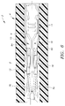
- an electrical connector 2 comprises an insulative housing 4 having terminal receiving cavities 6 extending therethrough for receiving a stamped and formed electrical terminal 8.
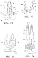
- the terminal 8 comprises an inner contact body 10 (also see Figures 8-10) and an outer backup spring 12 (also see Figures 12 and 13).
- the inner contact body 10 comprising a conductor connection section 14 extending axially into a transition section 16 which extends into a U-shaped body section 18 having a base wall 20 and side walls 22,24.
- a contact section 26 extends from the side walls 22,24 and comprises a pair of opposed cantilever beam contact arms 28 for receiving a mating tab terminal therebetween.
- One of the side walls 22 comprises an upper extension 30 that projects beyond an upper edge 32 of the opposing side wall 24.
- An upper edge 34 of the upper extension 30 has a profile similar in shape to the upper edge 32 and comprises a central raised portion 36 flanked on either side by front and rear clinching edges 38,39 respectively for clinching of the outer backup spring thereto as will be described further on.
- the other side wall 24 similarly has front and rear clinching edges 41,43. Projecting from a lower edge 40, in a position substantially opposite the front clinching edge 41 is a lower extension 42 having a lower edge 44 that projects below the base wall 20.
- the inner contact body is shown in a partially stamped state prior to bending into a U-shape whereby the approximate plain of symmetry is shown by the dotted line 46.
- the outer backup spring 12 is shown in various stages of its stamping and forming process, whereby Figures 12 and 13 show the outer backup spring just prior to removal from the carrier strip 48 and clinching around the inner contact body 10.
- the outer backup spring 12 comprises a body section 50 for wrapping around the inner contact body section 18; and extending axially therefrom for positioning substantially parallel and against the cantilever beam contact arms 28, are cantilever beam spring arms 52 having arcuate projections 54 proximate their free ends for applying spring pressure against the inner contact body arms 28 for increased resiliency thereof.
- the body section 50 comprises a base wall 56, opposed side walls 57,58 and extending from upper edges 60 thereof, are front and rear clinching tabs 59,61,62,63 respectively. Locking lances 64 are stamped out of the side walls 57,58 and project obliquely rearwardly for locking the terminal 8 within the housing cavity 6 as shown in Figure 6.
- the side walls 57,58 are mounted substantially against the inner contact side walls 24,22 respectively, whereby one side wall 58 of the outer backup spring extends further upwards than the other side wall such that the front and rear clinching tabs 62,63 thereof can be clinched over the clinching edges 38,39 respectively of the inner contact body sidewall 22.
- the latter is best seen in Figures 4 and 5 whereby the clinching arms 59,61,62,63 are clinched over their respective side walls 24,22 of the inner contact body in a similar manner except for the one side wall extending further than the other.
- the front and rear clinching arms 59,61 and 62,63 of each side wall 22,24 respectively are attached proximate their free ends with bridge portions 66 that are folded over the central raised portions 36 and against the side walls 22,24. Adjacent the bridging portion 66 is a cutout 68 to allow positioning of the upper edge protrusion 30,36 to fit between the front end rear clinching arms 59,61 and 62,63 respectively thus providing a secure retention means of the outer backup spring to the inner contact body.
- the side wall 57 has a lower U-shaped extension 70 that extends below the base wall 56 in such a manner as to fit around the lower extension 42 of the inner contact body side wall 24.
- the U-shaped lower extension 70 is thus disposed at a substantially opposing diagonal disposition with respect to the upper extension 30,60.
- the U-shaped lower extension 70 has substantially similar proportions and profile in mirror image to the U-shaped clinching arms 62,63 that are folded over the clinching edges 38,39 of the inner contact body side wall 22.
- the diagonally opposed upper and lower extensions of the outer backup spring and inner contact body form polarizing extensions 70,72 respectively for the purpose hereafter described with reference to Figure 7.
- the housing cavity 6 has an almost square profile defined by opposed side faces 74,76 and extending therebetween opposed top and bottom faces 78,80 respectively. Tapered lead-in surfaces 82,84 serve to guide the contact arms and body section between the side walls 74,76.
- the side face 76 extends upwards beyond the side face 74 and extends into a substantially U-shaped corner that joins the top face 78 and forms a substantially U-shaped cavity section 86 for receiving either of the polarizing extensions 72,70 therein.
- the other side face 74 extends lower than the side face 76 and forms a substantially U-shaped cavity section 88 for receiving either of the polarizing extension 70,72 therein. Due to the diagonally opposed polarizing cavity sections 86,88, the general cavity cross-sectional profile is approximate rhombic. The latter allows close centerline to centerline positioning of cavities 6 stacked upon each other and which need to be separated by a wall section 90 that requires a minimum thickness for strength, manufacturability and other properties such as electrical resistance therethrough.
- the terminals 8 can be inserted into the cavities 6 in either a 0° disposition or 180° disposition with respect thereto as soon by the terminal 8' 90° disposition as shown by the terminal 8'' must however be avoided as a mating tab terminal for insertion between the contact arms 88 is not possible in this disposition.
- the terminal 8'' is shown positioned against one of the side wall 74 and whereby the upper polarizing extension 70'' manages to insert into the cavity against the side face 76.
- the lower polarizing extension 72'' however abuts the tapered lead-in surface 84 and prevents insertion of the terminal 8'' into the cavity 6.
- polarizing extension 70,72 Due to the use of opposingly projecting polarizing extension 70,72 they can extend only half the distance beyond the terminal in comparison to a terminal having only one polarizing extension. Furthermore, due to the positioning of the polarizing extensions 70,72 adjacent the side faces 74,76, the polarizing extension abut against corner sections of the housing cavity walls which are far sturdier and less flexible than a central portion of the cavity separating walls such as 90, whereby a polarizing extension positioned centrally may allow forcing of the terminal into the cavity 6 by deformation of the housing wall 90. Furthermore, as the polarizing extensions 70,72 and corresponding cavities 86,88 are diagonally opposed, terminals can be stacked in a compact configuration while maintaining a minimum wall thickness T of the wall 90 between adjacent cavities 6. A further advantage is the ability to insert the terminals in a 0 or 180° disposition which increases the assembly possibility thereof.
- the diagonally opposed polarizing extensions 70,72 allow for a more compact configuration whilst nevertheless providing a sturdy and reliable polarizing system which allows 0 or 180° polarization.
Landscapes
- Engineering & Computer Science (AREA)
- Manufacturing & Machinery (AREA)
- Connector Housings Or Holding Contact Members (AREA)
Applications Claiming Priority (2)
| Application Number | Priority Date | Filing Date | Title |
|---|---|---|---|
| FR9411087A FR2724774A1 (fr) | 1994-09-16 | 1994-09-16 | Connecteur electrique a bornes polarisees |
| FR9411087 | 1994-09-16 |
Publications (3)
| Publication Number | Publication Date |
|---|---|
| EP0702430A2 true EP0702430A2 (de) | 1996-03-20 |
| EP0702430A3 EP0702430A3 (de) | 1997-10-22 |
| EP0702430B1 EP0702430B1 (de) | 2000-03-15 |
Family
ID=9467014
Family Applications (1)
| Application Number | Title | Priority Date | Filing Date |
|---|---|---|---|
| EP19950114234 Expired - Lifetime EP0702430B1 (de) | 1994-09-16 | 1995-09-11 | Polarisierte Anschlussbuchsen und elektrischer Verbinder mit derartigen Buchsen |
Country Status (3)
| Country | Link |
|---|---|
| EP (1) | EP0702430B1 (de) |
| DE (1) | DE69515582T2 (de) |
| FR (1) | FR2724774A1 (de) |
Cited By (2)
| Publication number | Priority date | Publication date | Assignee | Title |
|---|---|---|---|---|
| EP0986142A1 (de) * | 1998-09-09 | 2000-03-15 | Framatome Connectors International | Elektrischer Kontakt für Verbinder mit Kodierrippe |
| US12494602B2 (en) | 2021-07-07 | 2025-12-09 | FCI NANTONG Ltd. | Combo connector |
Families Citing this family (1)
| Publication number | Priority date | Publication date | Assignee | Title |
|---|---|---|---|---|
| WO2014063142A1 (en) * | 2012-10-19 | 2014-04-24 | Lear Corporation | Electrical terminal |
Family Cites Families (4)
| Publication number | Priority date | Publication date | Assignee | Title |
|---|---|---|---|---|
| US4531808A (en) * | 1983-05-16 | 1985-07-30 | Ford Motor Company | Blade coupling terminal |
| US5188545A (en) * | 1990-06-05 | 1993-02-23 | Amp Incorporated | Electrical socket terminal |
| DE9106780U1 (de) * | 1991-06-03 | 1992-10-01 | Grote & Hartmann Gmbh & Co Kg, 5600 Wuppertal | Kastenfeder |
| GB9225136D0 (en) * | 1992-12-01 | 1993-01-20 | Amp Gmbh | Electrical socket terminal |
-
1994
- 1994-09-16 FR FR9411087A patent/FR2724774A1/fr not_active Withdrawn
-
1995
- 1995-09-11 EP EP19950114234 patent/EP0702430B1/de not_active Expired - Lifetime
- 1995-09-11 DE DE1995615582 patent/DE69515582T2/de not_active Expired - Fee Related
Cited By (2)
| Publication number | Priority date | Publication date | Assignee | Title |
|---|---|---|---|---|
| EP0986142A1 (de) * | 1998-09-09 | 2000-03-15 | Framatome Connectors International | Elektrischer Kontakt für Verbinder mit Kodierrippe |
| US12494602B2 (en) | 2021-07-07 | 2025-12-09 | FCI NANTONG Ltd. | Combo connector |
Also Published As
| Publication number | Publication date |
|---|---|
| DE69515582T2 (de) | 2000-09-14 |
| EP0702430B1 (de) | 2000-03-15 |
| EP0702430A3 (de) | 1997-10-22 |
| FR2724774A1 (fr) | 1996-03-22 |
| DE69515582D1 (de) | 2000-04-20 |
Similar Documents
| Publication | Publication Date | Title |
|---|---|---|
| US5151056A (en) | Electrical contact system with cantilever mating beams | |
| EP0760540B1 (de) | Elektrischer Stecker mit verbessertem Verbinderpositioniermittel | |
| US6244910B1 (en) | Electrical box contact with stress limitation | |
| US3069652A (en) | Electrical connector for printed circuit boards | |
| EP1120861B1 (de) | Elektrischer Verbinder mit verbesserter Kontaktbüchse | |
| US6375502B2 (en) | Connector | |
| EP0472006A1 (de) | Elektrischer Steckverbinder mit Mitteln zum Sicherstellen einer zuverlässigen elektrischen Verbindung | |
| EP0935827B1 (de) | Kontakt mit verriegelung zur kontakthalterung und dafür geeignetes gehaüse | |
| US6626701B2 (en) | Connector | |
| US5458502A (en) | IDC Terminal with back-up spring | |
| EP0549958A2 (de) | Elektrische Kontaktbüchse mit verbesserter Kontaktkraft | |
| EP1039590A2 (de) | Elektrische Steckverbinderanordnung | |
| US6840824B2 (en) | Female terminal and electric connector with the female terminals | |
| JPH05258792A (ja) | 過度応力防止手段を有する雄電気端子 | |
| US6994596B2 (en) | Terminal fitting, a connector provided therewith and method of forming a terminal fitting | |
| US7147522B2 (en) | Terminal fitting and a connector provided therewith | |
| US7204728B2 (en) | Terminal fitting and a connector provided therewith | |
| EP0638959A2 (de) | Elektrische Anschlussbuchse | |
| JP3717057B2 (ja) | コネクタのサイドスペーサ構造 | |
| EP1134848B1 (de) | Steckverbinder und Anschlusskontaktgruppe | |
| JP2868405B2 (ja) | 雌型端子 | |
| EP0488349A2 (de) | Verbinder mit Kontaktabstandsplatte mit keilförmigen Kanälen | |
| EP0701299B1 (de) | Elektrische Kontaktbuchse | |
| US7033194B1 (en) | Standardized electrical terminal | |
| EP0702430B1 (de) | Polarisierte Anschlussbuchsen und elektrischer Verbinder mit derartigen Buchsen |
Legal Events
| Date | Code | Title | Description |
|---|---|---|---|
| PUAI | Public reference made under article 153(3) epc to a published international application that has entered the european phase |
Free format text: ORIGINAL CODE: 0009012 |
|
| AK | Designated contracting states |
Kind code of ref document: A2 Designated state(s): DE ES FR GB IT SE |
|
| PUAL | Search report despatched |
Free format text: ORIGINAL CODE: 0009013 |
|
| AK | Designated contracting states |
Kind code of ref document: A3 Designated state(s): DE ES FR GB IT SE |
|
| 17P | Request for examination filed |
Effective date: 19980226 |
|
| GRAG | Despatch of communication of intention to grant |
Free format text: ORIGINAL CODE: EPIDOS AGRA |
|
| RTI1 | Title (correction) |
Free format text: POLARIZED TERMINALS AND ELECTRICAL CONNECTOR COMPRISING SUCH TERMINALS |
|
| 17Q | First examination report despatched |
Effective date: 19990628 |
|
| GRAG | Despatch of communication of intention to grant |
Free format text: ORIGINAL CODE: EPIDOS AGRA |
|
| GRAH | Despatch of communication of intention to grant a patent |
Free format text: ORIGINAL CODE: EPIDOS IGRA |
|
| GRAH | Despatch of communication of intention to grant a patent |
Free format text: ORIGINAL CODE: EPIDOS IGRA |
|
| GRAA | (expected) grant |
Free format text: ORIGINAL CODE: 0009210 |
|
| AK | Designated contracting states |
Kind code of ref document: B1 Designated state(s): DE ES FR GB IT SE |
|
| PG25 | Lapsed in a contracting state [announced via postgrant information from national office to epo] |
Ref country code: SE Free format text: THE PATENT HAS BEEN ANNULLED BY A DECISION OF A NATIONAL AUTHORITY Effective date: 20000315 Ref country code: IT Free format text: LAPSE BECAUSE OF FAILURE TO SUBMIT A TRANSLATION OF THE DESCRIPTION OR TO PAY THE FEE WITHIN THE PRE;WARNING: LAPSES OF ITALIAN PATENTS WITH EFFECTIVE DATE BEFORE 2007 MAY HAVE OCCURRED AT ANY TIME BEFORE 2007. THE CORRECT EFFECTIVE DATE MAY BE DIFFERENT FROM THE ONE RECORDED.SCRIBED TIME-LIMIT Effective date: 20000315 Ref country code: ES Free format text: THE PATENT HAS BEEN ANNULLED BY A DECISION OF A NATIONAL AUTHORITY Effective date: 20000315 |
|
| REF | Corresponds to: |
Ref document number: 69515582 Country of ref document: DE Date of ref document: 20000420 |
|
| ET | Fr: translation filed | ||
| PLBE | No opposition filed within time limit |
Free format text: ORIGINAL CODE: 0009261 |
|
| STAA | Information on the status of an ep patent application or granted ep patent |
Free format text: STATUS: NO OPPOSITION FILED WITHIN TIME LIMIT |
|
| 26N | No opposition filed | ||
| REG | Reference to a national code |
Ref country code: GB Ref legal event code: IF02 |
|
| PGFP | Annual fee paid to national office [announced via postgrant information from national office to epo] |
Ref country code: GB Payment date: 20020808 Year of fee payment: 8 |
|
| PG25 | Lapsed in a contracting state [announced via postgrant information from national office to epo] |
Ref country code: GB Free format text: LAPSE BECAUSE OF NON-PAYMENT OF DUE FEES Effective date: 20030911 |
|
| GBPC | Gb: european patent ceased through non-payment of renewal fee |
Effective date: 20030911 |
|
| PGFP | Annual fee paid to national office [announced via postgrant information from national office to epo] |
Ref country code: DE Payment date: 20040930 Year of fee payment: 10 |
|
| PG25 | Lapsed in a contracting state [announced via postgrant information from national office to epo] |
Ref country code: DE Free format text: LAPSE BECAUSE OF NON-PAYMENT OF DUE FEES Effective date: 20060401 |
|
| PGFP | Annual fee paid to national office [announced via postgrant information from national office to epo] |
Ref country code: FR Payment date: 20140917 Year of fee payment: 20 |