EP0702508B1 - Elektronisches Vorschaltgerät für Gasentladungslampen mit unscharfer Logik - Google Patents
Elektronisches Vorschaltgerät für Gasentladungslampen mit unscharfer Logik Download PDFInfo
- Publication number
- EP0702508B1 EP0702508B1 EP95114572A EP95114572A EP0702508B1 EP 0702508 B1 EP0702508 B1 EP 0702508B1 EP 95114572 A EP95114572 A EP 95114572A EP 95114572 A EP95114572 A EP 95114572A EP 0702508 B1 EP0702508 B1 EP 0702508B1
- Authority
- EP
- European Patent Office
- Prior art keywords
- lamp
- ist
- gas discharge
- discharge lamp
- current
- Prior art date
- Legal status (The legal status is an assumption and is not a legal conclusion. Google has not performed a legal analysis and makes no representation as to the accuracy of the status listed.)
- Expired - Lifetime
Links
Images


Classifications
-
- H—ELECTRICITY
- H05—ELECTRIC TECHNIQUES NOT OTHERWISE PROVIDED FOR
- H05B—ELECTRIC HEATING; ELECTRIC LIGHT SOURCES NOT OTHERWISE PROVIDED FOR; CIRCUIT ARRANGEMENTS FOR ELECTRIC LIGHT SOURCES, IN GENERAL
- H05B41/00—Circuit arrangements or apparatus for igniting or operating discharge lamps
- H05B41/14—Circuit arrangements
- H05B41/36—Controlling
- H05B41/38—Controlling the intensity of light
- H05B41/39—Controlling the intensity of light continuously
- H05B41/392—Controlling the intensity of light continuously using semiconductor devices, e.g. thyristor
-
- Y—GENERAL TAGGING OF NEW TECHNOLOGICAL DEVELOPMENTS; GENERAL TAGGING OF CROSS-SECTIONAL TECHNOLOGIES SPANNING OVER SEVERAL SECTIONS OF THE IPC; TECHNICAL SUBJECTS COVERED BY FORMER USPC CROSS-REFERENCE ART COLLECTIONS [XRACs] AND DIGESTS
- Y10—TECHNICAL SUBJECTS COVERED BY FORMER USPC
- Y10S—TECHNICAL SUBJECTS COVERED BY FORMER USPC CROSS-REFERENCE ART COLLECTIONS [XRACs] AND DIGESTS
- Y10S315/00—Electric lamp and discharge devices: systems
- Y10S315/04—Dimming circuit for fluorescent lamps
-
- Y—GENERAL TAGGING OF NEW TECHNOLOGICAL DEVELOPMENTS; GENERAL TAGGING OF CROSS-SECTIONAL TECHNOLOGIES SPANNING OVER SEVERAL SECTIONS OF THE IPC; TECHNICAL SUBJECTS COVERED BY FORMER USPC CROSS-REFERENCE ART COLLECTIONS [XRACs] AND DIGESTS
- Y10—TECHNICAL SUBJECTS COVERED BY FORMER USPC
- Y10S—TECHNICAL SUBJECTS COVERED BY FORMER USPC CROSS-REFERENCE ART COLLECTIONS [XRACs] AND DIGESTS
- Y10S315/00—Electric lamp and discharge devices: systems
- Y10S315/07—Starting and control circuits for gas discharge lamp using transistors
-
- Y—GENERAL TAGGING OF NEW TECHNOLOGICAL DEVELOPMENTS; GENERAL TAGGING OF CROSS-SECTIONAL TECHNOLOGIES SPANNING OVER SEVERAL SECTIONS OF THE IPC; TECHNICAL SUBJECTS COVERED BY FORMER USPC CROSS-REFERENCE ART COLLECTIONS [XRACs] AND DIGESTS
- Y10—TECHNICAL SUBJECTS COVERED BY FORMER USPC
- Y10S—TECHNICAL SUBJECTS COVERED BY FORMER USPC CROSS-REFERENCE ART COLLECTIONS [XRACs] AND DIGESTS
- Y10S706/00—Data processing: artificial intelligence
- Y10S706/90—Fuzzy logic
Definitions
- the present invention relates to an electronic ballast for Gas discharge lamps according to the preamble of claim 1.
- Ballasts are known in the field of electronic ballasts that work with a positively controlled oscillator and are dimmable. For dimming a gas discharge lamp to be connected to the electronic ballast the current flowing through the lamp changes. This is controlled using the Oscillator achieved by changing the lamp current frequency.
- the Gas discharge lamp is controlled via a series resonance circuit in its load circuit. Approximately corresponds to the frequency of the current delivered to the gas discharge lamp the resonance frequency of the series resonance circuit, the lamp is ignited. By Shift the current frequency from the resonance frequency of the series resonant circuit away or to the resonance frequency of the resonant circuit, the current of the Gas discharge lamp can be lowered or increased. To regulate the lamp current the actual value of the current lamp current is measured and with a setpoint compared. A corresponding current controller generates based on these two Values a control value for the current. The lamp voltage is set accordingly Lamp curve on.
- Gas discharge lamps have a negative characteristic. That means that the The lamp voltage drops when the lamp current increases. The lamp should be brighter the current must be regulated up. But it works because of negative characteristic of the lamp counteracts the drop in lamp voltage.
- the lamp current but the Lamp power, d. H. to regulate the product of lamp current and lamp voltage.
- the lamp power is in turn adjusted via the frequency.
- the actual value of the lamp power is measured and compared with a target value.
- the frequency depends on the sign of the control difference from the resonance frequency of the one present in the load circuit of the lamp Series resonance circuit away or shifted to the resonance frequency.
- Such Ballasts have the disadvantage that only the lamp power can be monitored. Because only the product of lamp voltage and lamp current is regulated, it is not excluded that the electronic ballast may be in an unstable or prohibited range is controlled. For example conceivable that a limit value for the maximum permissible lamp power is maintained is exceeded, however, a limit value for a maximum permissible lamp current becomes.
- the invention has for its object an improved electronic Ballast for gas discharge lamps to specify, which in particular the avoids disadvantages explained above.
- fuzzy logic control technology i.e. the The brightness of the connected gas discharge lamp is controlled by a fuzzy controller regulated that, depending on at least one input variable, a manipulated variable for a physical size of the inverter or the load circuit of the electronic Ballast generated.
- the lamp current is preferably regulated, i.e. the The actual value of the lamp current is recorded and fed to a comparator which measures the actual value with a specified target value and compares the resulting control difference passes on to the fuzzy controller.
- the fuzzy controller generates according to the rules of Fuzzy logic depending on the control difference a control signal for the Inverter or the load circuit.
- the control signal of the Fuzzy controller the frequency or the duty cycle of the lamp current or the Lamp voltage set.
- the fuzzy controller ensures by setting up Decision rules, into which corresponding empirical values can flow, that the Lamp is not controlled in unstable areas.
- the Ambient temperature and / or the filament resistance of the gas discharge lamp is detected and be fed to the fuzzy controller.
- the Fuzzy controller in connection with the detected lamp voltage a statement about make the degree of aging of the connected gas discharge lamp.
- the setpoint signal of the comparator of the control device can be external, e.g. be changeable via a dimmer and also stored as a predetermined fixed value.
- the fuzzy controller as exponential or logarithmic function element, so that between the Output variable of the fuzzy controller and its input variable an exponential or there is a logarithmic relationship. This is - as explained below will be - particularly advantageous to a linear relationship between the of the brightness output received by the gas discharge lamp and that of the To create observers subjectively perceived brightness.
- a special feature of fuzzy logic is that not all input variables are used for Obtaining the output variable must be evaluated.
- Reaches e.g. one or the fuzzy controller sets several of the input variables regardless of the remaining input variables, the output variable to one certain value.
- the output value of the fuzzy controller depends only on the Design of the decision rules, i.e. the so-called fuzzy rules.
- the fuzzy logic is also advantageous for detecting the lamp type connected gas discharge lamp used. From EP-A-0 413 991 it is known to determine the ignition voltage of the connected gas discharge lamp and on the basis the determined ignition voltage to infer the lamp type. The determination of Ignition voltage depends, among other things, on the manufacturer, the degree of aging Gas filling and the heating of the lamp, so that there are overall fluctuations in Range between 10% and 20% when determining the ignition voltage.
- Claim 13 specifies a new method, by means of which by determining at least one operating parameter after startup of the gas discharge lamp Lamp type can be determined.
- the solution according to the invention has the advantage on that several different operating parameters for evaluating the lamp type can be used, the different volatility exhibit. For this reason, it is advantageous to determine the lamp type Fuzzy logic is used because of the free design of the fuzzy rules allows the individual operating parameters to be evaluated individually or in combination. A corresponding solution is given in claim 14.
- the lamp type of the connected gas discharge lamp has been determined, then this preferably in a memory in the form of various operating parameters or stored in the form of the corresponding lamp characteristic so that the lamp type does not have to be constantly checked and determined as long as the corresponding one Gas discharge lamp has not been replaced.
- the lamp can be replaced determined by detecting a possible break in the heating circuit become.
- the corresponding controller of the electronic controls Ballast the brightness of the connected gas discharge lamp in Depending on their type.
- the type of lamp found is optical and / or indicated acoustically so that the user is constantly aware of the type of lamp used.
- an electronic ballast for Gas discharge lamps used the fuzzy logic.
- Fuzzy logic The generally valid statements of Fuzzy logic will be briefly described below.
- Fuzzy logic is logic that works with imprecise statements.
- the single ones Quantities of the fuzzy logic are quantified, i.e. it is for each size only certain value ranges permitted.
- the individual sizes are quantified according to so-called membership functions, the current value being one Input variable of the fuzzy logic a corresponding value range according to its Affiliation function and a corresponding truth value (degree of fulfillment) is assigned.
- the quantified input variables are with their Truth values combined according to certain decision rules, so that a - likewise quantified - output variable of the fuzzy logic system can be derived can.
- the quantified output variable is then converted into a concrete one Output variable converted according to a certain method.
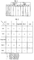
- the heating of a room depends on the interior and Outside temperature of the room should be regulated.
- the two input variables i.e. the inside and outside temperature
- the Output variable i.e. for example the control value for the temperature of the Boiler
- everyone Size is assigned only five ranges of values, according to their corresponding Membership function are delimited from each other.
- the course of the membership functions is by no means mandatory.
- the individual areas can optionally also be non-overlapping and triangular.
- a concrete input value of the fuzzy controller is now based on its corresponding one Membership function assigned to one or more of the areas, depending on whether the areas for the concrete input value overlap or not. Of further is for the concrete input value and for each of its assigned Areas a corresponding truth value or degree of fulfillment.
- the output variable of the controller is also quantified, ie divided into certain value ranges.
- the identifiers label
- strong heating "slight heating”
- Constant “slight cooling”
- strong cooling are available for the output variable, which are each defined between specific temperature limits. The individual temperature limits are determined based on certain empirical values. If the designation for the output variable is "slight cooling” with a truth value of 1.0, this would mean the manipulated variable T 4 for the heating. If the output variable has a correspondingly low truth value, the control value for the heating changes according to the membership function C.
- the fuzzy logic provides the minimum value of the for an AND combination of the input variables two input variables and for an OR combination the maximum value of the two Input variables, so that in principle the fuzzy logic corresponds to the Boolean logic, but with the exception that the fuzzy logic also contains unsharp values between 0 and 1 can combine with each other.
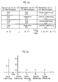
- the individual value pairs of the input variables A and B which correspond to the Affiliation functions in Figure 1 are now obtained after certain rules, the so-called fuzzy rules, combined with each other.
- fuzzy rules For each a combination of a pair of values of input variable A with a pair of values the input variable B results in a certain quantified output variable C.
- the Individual fuzzy rules are set up based on certain empirical values. On the corresponding combination diagram is shown in FIG. 3 with the associated legend. The assignment of a specific identifier of the output variable C to one certain combination of input variables A and B is initially without Consideration of the corresponding truth values.
- the truth value corresponds to the quantified one Output variable C the minimum of the two truth values of each other Combined input variables A and B.
- Figure 4a four pairs of values for the output variable C received.
- the last remaining step to determine a concrete manipulated variable for the Heating is the implementation of the four pairs of values of the quantified output variable C in a specific controller manipulated variable.
- the four different ones Value pairs of the output variable C combined with each other to a specific one to receive a concrete manipulated variable. This process is called defuzzification.
- Figure 4b is intended to illustrate the operation of this method.
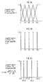
- the associated truth values are applied to the individual identifiers of the output variable C.
- the identifier "strong warming” with a truth value of 0.7 was obtained once for the quantified initial variable C and three times the identifier "slight warming" with a truth value of 0.3 each.
- the remaining identifiers of the associated membership function C have not been determined, which corresponds to a truth value 0 for these identifiers.
- the calculated center of gravity corresponds to the concrete manipulated variable for the boiler temperature. If, for example, it is assumed that T 1 corresponds to a heating boiler temperature of 80 ° C and T 2 corresponds to a heating boiler temperature of 70 ° C, the control value for the heating boiler temperature would be 74 ° C.
- the inventive method results electronic ballast compared to the known electronic ballast a number of advantages.
- the main advantages of fuzzy logic are for example in "Fuzzy logic, the fuzzy logic conquers technology", Daniel McNeill and Paul Freiberger, Droemer Knaur Verlag, 1994. So points for example, the logic control over digital control has the advantage that a possibly existing control difference is gradually reduced, while at comparable digital controllers often exceed or fall below the target value is so that this overregulation must be quickly compensated for.
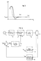
- the fuzzy logic can be used in particular when igniting gas discharge lamps become. Gas discharge lamps are made by approximating the frequency of the Lamp current to the resonance frequency of the existing in the load circuit Series resonance circuit switched on or ignited. Should the lamp after Turn on to operate at a low brightness, so it is necessary after switch the brightness of the lamp down quickly when switching on, whereby at ordinary systems undershoot below the desired brightness occur what in the worst case, the lamp can go out.
- FIG. 5 shows (a) the time-dependent characteristic of the lamp brightness E during an ignition process of the gas discharge lamp. It can be seen that while the lamp brightness is being reduced, the target brightness E target is fallen short of, so that compensation control is necessary to achieve the target value. With the fuzzy logic, on the other hand, an improved approach to the desired brightness value is possible without overshoot or undershoot. For comparison, FIG. 5 shows the brightness characteristic curve (b) that can be achieved with a fuzzy controller.
- fuzzy logic enables a particularly fast response or Setting the output size possible so that when using a fuzzy controller an existing control difference, as can also be seen in FIG. 5, is compensated more quickly can be.
- Other advantages of fuzzy logic can be seen in the fact that compared less information is required about known control systems and additionally this Verbal formulations can be found immediately because the Fuzzy logic works with linguistic terms. For this reason, too human knowledge is brought into the system in the simplest way, without translation into complex mathematical models.
- FIG. 6 shows a first Embodiment of the ballast according to the invention.
- the electronic ballast comprises a rectifier 2, which is fed by a supply voltage source 1 and is connected to an inverter 3.
- a load circuit 4 is connected to the inverter 3, which serves to control a gas discharge lamp 5 and usually contains, inter alia, a series resonance circuit for igniting the connected gas discharge lamp 5.
- the electronic ballast comprises a control device which comprises a controller 7 and a comparator 6.
- the controller 7 is designed as a fuzzy controller.
- the control device can be arranged in the electronic ballast or also externally.
- the lamp current of the connected gas discharge lamp 5 is preferably regulated.
- the lamp current is detected by a current measuring element 8 and the instantaneous actual value of the lamp current i is output to the comparator 6 of the control device.
- the comparator 6 compares the actual value i ist of the lamp current with a predetermined lamp current setpoint i soll , the current setpoint i soll corresponding to a predetermined dimming setpoint, which is output, for example, by a dimmer to the comparator 6.
- Be the current target value i soll or the predetermined dimming setpoint can be changed in both time manually, as is the case with ordinary Dimm healthyen, as well as present an invariable fixed value, for example, stored in the form.
- the comparator 6 determines a control difference value i diff , which is applied to the fuzzy controller 7, on the basis of the comparison of the current setpoint i soll with the actual value i ist .
- the fuzzy controller generates a control value y for the inverter 3 depending on the input variable i diff.
- the lamp brightness is usually set by adjusting the frequency f or the pulse duty factor d of the lamp current of the connected gas discharge lamp 5.
- the fuzzy controller can also be used to regulate the lamp voltage or lamp power.
- a voltage measuring element 9 is provided which detects the instantaneous lamp voltage and generates an actual value of the lamp voltage u ist .
- the lamp voltage actual value signal u ist determined by the voltage measuring element 9 is then applied to the comparator 6 instead of the lamp current actual value signal i ist and compared there with a voltage target value, the comparator 6 then correspondingly Control difference signal of the voltage to the fuzzy controller.
- the current control as shown in FIG. 6, represents the common type of control.
- the reason for this can be seen in the fact that, due to the negative characteristic curve of the lamp, a plurality of lamp current values can be assigned for one lamp voltage value, so that ambiguities would arise in the case of voltage regulation. In contrast, there is only a single lamp voltage value for each lamp current value, so that ambiguities are avoided with the aid of the current control.
- the lamp voltage u detected by the voltage measuring element 9 is to be applied directly to the fuzzy controller 7 as a further input variable of the fuzzy controller 7.
- the fuzzy controller 7 combines the two input values i diff and u which are present in fuzz repeater form, and determines capped decision rules based on previously a corresponding control value signal y for the inverter 3 or the load circuit 4 of the electronic ballast. Due to the properties of the fuzzy logic described above, in contrast to conventional controllers, it is possible in principle to evaluate certain input variables and to combine them, whereby neither the input variables nor the output variable need to belong to the same physical variable (eg current or voltage).
- FIG. 7 shows a further exemplary embodiment, which differs from the first exemplary embodiment shown in FIG. 6 in that, as already described above, the lamp voltage is also monitored by a voltage measuring element 9 and a corresponding actual lamp voltage value u is applied to the fuzzy Controller 7 is created as an additional input variable. Furthermore, in FIG. 7, the fuzzy controller 7 generates a further output signal z in addition to the control value y for the inverter 3. In the drawing, the corresponding parts of the block diagrams are identified by identical reference numerals. In the second exemplary embodiment shown in FIG. 7, the fuzzy controller 7 can draw conclusions about the aging of the connected gas discharge lamp 5 with the aid of the supplied voltage u ist .
- the fuzzy controller assigns each fuzzified lamp voltage value u is a corresponding degree of aging on the basis of previously established decision rules, the degrees of aging also being present in fuzzified form. After defuzzification of the degree of aging has taken place, ie the conversion of the fuzzified degree of aging into a concrete aging value, the fuzzy controller 7 outputs the corresponding output signal z. Furthermore, the feedback voltage u ist can also be used for constant regulation of the lamp power. The lamp voltage of the gas discharge lamp 5 changes depending on the ambient temperature, so that it is necessary for constant regulation of the lamp power, depending on the instantaneous lamp voltage u , the current value has to be increased or decreased.
- the brightness of the connected gas discharge lamp is approximately proportional to the lamp power.
- FIG. 7 it is also indicated that, in addition to the control difference value i diff, alternatively or alternatively also its temporal gradient i ' diff , ie the change in the control difference i diff over time , can be fed to the fuzzy controller 7, since, for example, also when the degree of aging is detected of the connected gas discharge lamp are interested in the rate of change of the lamp current over time and can accordingly be used to determine the degree of aging.
- the output variable Y does not become inherent overlapping value ranges, but by individual, discrete values, so-called Singletons, each modeled with the truth value 1.0.
- the values of the singletons result from inserting the maximum values of the value ranges of the input variable X into the function to be described by the fuzzy component.
- the straight line equation we get for the singletons have the same values as for the maximum values of the value ranges of the Input variable X.
- Figure 9 shows a third embodiment of the invention according to the invention, at that in connection with an electronic ballast for a Gas discharge lamp use is made of the fuzzy logic.
- the exemplary embodiment shown in FIG. 9 is independent of the fuzzy logic the inventive idea is based on different operating parameters of the connected gas discharge lamp after commissioning to the lamp type to close the gas discharge lamp 5.
- the ignition voltage of a connected gas discharge lamp determine and infer the lamp type based on the determined ignition voltage.
- the determination of the ignition voltage depends on many different ones Requirements or parameters, so that the ignition voltage is only inaccurate can be determined.
- the invention proposes at least one Determine the operating parameters of the lamp after its commissioning and on the basis of this operating parameter to infer the lamp type.
- the basic procedure for lamp detection is briefly described below described. It is assumed that the Control device to be controlled physical quantity is the lamp current. To Commissioning of the gas discharge lamp will have different lamp current setpoints specified and the lamp current set according to these setpoints. To each Lamp current setpoint becomes the corresponding actual value of those to be monitored Operating size of the gas discharge lamp determined. The individual thus preserved Actual values of the operating variables are combined with one another, so that subsequently on the basis of the actual values depending on the specified lamp current setpoints Lamp type of the connected gas discharge lamp can be closed. To This purpose is, for example, the evaluation of various predefined ones Characteristic curves of the individual lamp types conceivable. For example, the Current / voltage characteristics of different lamp types can be known. As before different current setpoints are set and accordingly the Lamp voltage determined depending on the set current setpoints. Based the determined current / voltage value pairs and the various existing ones Current / voltage characteristics can be based on the lamp type of the connected Gas discharge lamp can be closed.
- fuzzy logic is advantageously used for the evaluation of individual operating parameter values or different operating parameters in combination.
- a corresponding embodiment is shown in FIG 9.
- the fuzzy logic component 14 specifies current setpoints for setting the lamp current to a control device and detects the actual values R ist , u ist and T ist depending on the set current setpoints. In this way, several actual lamp values R ist , u ist and T ist are assigned to several lamp current values that have been set.
- the controller 7 shown in Figure 9 can also be implemented as a fuzzy controller, in which a supply of the lamp voltage detected is u is as further input variable of the fuzzy controller for more precise control of the lamp current of advantage.
- a supply of the lamp voltage detected is u is as further input variable of the fuzzy controller for more precise control of the lamp current of advantage.
- the fuzzy logic component 14 is the respective (fuzz er) in quantified form the present actual values of the monitored operating variables R, u and T is according to the procedure of Fuzzy logic assigns a corresponding lamp type.
- the decision rules were preferably established on the basis of known characteristic curves of the different lamp types.
- FIG. 10 shows an example of the assignment of the lamp type to the detected actual values of the outside temperature T ist , the filament resistance R ist and the lamp voltage u ist , different current-voltage characteristics being shown for different lamp types.
- the characteristics shown show the current-voltage characteristics of three different lamp types for the temperature range T ist ⁇ 25 ° C and for a filament resistance R ist below a certain limit. For other areas of the temperature T ist and the coil resistance R ist , further characteristic curves are recorded or are already available.
- the voltage range of the lamp voltage u L is divided into several ranges U 1 to U 5 , ie quantified or fuzzified.
- a memory 13 is advantageous with the fuzzy logic 14 connected so that after determining the lamp type, this lamp type for example in the form of the corresponding lamp characteristic or in the form of various operating parameter values can be stored in the memory.
- this lamp type for example in the form of the corresponding lamp characteristic or in the form of various operating parameter values can be stored in the memory.
- the lamp type can also be indicated acoustically or optically be so that the user during the operation of a gas discharge lamp the connected lamp type is constantly informed.
- According to the invention continues proposed to delete the memory after each lamp change. So can for example by detecting an interruption in the heating circuit Gas discharge lamp using a heating current measuring element 12 detects a lamp change and then the memory will be deleted.
- said fuzzy logic component 14 defines a respective current target value i soll according to the determined lamp type to the comparator 6 of the control device.
Landscapes
- Circuit Arrangements For Discharge Lamps (AREA)
Description
Claims (25)
- Elektronisches Vorschaltgerät für Gasentladungslampen,dadurch gekennzeichnet,mit einem Gleichrichter (2) zum Gleichrichten einer Versorgungsspannung,mit einem von dem Gleichrichter gespeisten Wechselrichter (3),mit einem an den Wechselrichter angeschlossenen Lastkreis (4), an den mindestens eine Gasentladungslampe (5) anschließbar ist, undmit einer Regeleinrichtung (6, 7) mit einem Vergleicher (6) zum Regeln der Helligkeit der mindestens einen Gasentladungslampe,
daß die Regeleinrichtung einen Fuzzy-Regler (7) umfaßt, der abhängig von mindestens einem Eingangssignal (idiff, uist, Rist, Tist) als Ausgangssignal einen Stellwert (y) für einen physikalischen Parameter (f,d) des Wechselrichters (3) oder des Lastkreises (4) ermittelt. - Elektronisches Vorschaltgerät nach Anpruch 1,
gekennzeichnet durch
ein Strom-Meßglied (8) zum Ermitteln des Istwerts (iist) des Lampenstromes der mindestens einen Gasentladungslampe (5). - Elektronisches Vorschaltgerät nach Anspruch 2,
dadurch gekennzeichnet,daß der Vergleicher (6) durch Vergleich des Istwertes des Lampenstromes (iist) mit einem vorgebbaren Lampenstrom-Sollwert (isoll) einen Regeldifferenzwert (idiff) ermittelt, unddaß der Regeldifferenzwert als Eingangssignal am Fuzzy-Regler (7) anliegt. - Elektronisches Vorschaltgerät nach einem der vorhergehenden Ansprüche,
dadurch gekennzeichnet,
daß der physikalische Parameter des Wechselrichters (3), für den der Fuzzy-Regler (7) einen Stellwert (y) ermittelt, das Tastverhältnis (d) oder die Frequenz (f) des Lampenstromes oder der Lampenspannung der mindestens einen Gasentladungslampe (5) ist. - Elektronisches Vorschaltgerät nach einem der vorhergehenden Ansprüche,
gekennzeichnet durch
ein Spannungs-Meßglied (9) zum Ermitteln des Istwertes der Lampenspannung (uist) der mindestens einen Gasentladungslampe (5). - Elektronisches Vorschaltgerät nach Anspruch 5,
dadurch gekennzeichnet,
daß der vom Spannungs-Meßglied (9) ermittelte Istwert der Lampenspannung (uist) als Eingangssignal am Fuzzy-Regler (7) anliegt. - Elektronisches Vorschaltgerät nach Anspruch 6,
dadurch gekennzeichnet,
daß ein Temperatur-Meßglied (11) zum Ermitteln des Istwerts der Umgebungstemperatur (Tist) vorhanden ist, und daß der Istwert der Umgebungstemperatur (Tist) als Eingangssignal am Fuzzy-Regler anliegt. - Elektronisches Vorschaltgerät nach einem der Ansprüche 6 oder 7,
dadurch gekennzeichnet,daß ein Widerstand-Meßglied (10) zum Ermitteln des Istwertes des Wendelwiderstandes (Rist) der mindestens einen Gasentladungslampe (5) vorhanden ist, unddaß der Istwert des Wendelwiderstandes (Rist) als Eingangssignal am Fuzzy-Regler (7) anliegt. - Elektronisches Vorschaltgerät nach einem der Ansprüche 6 bis 8,
dadurch gekennzeichnet,
daß der Fuzzy-Regler (7) abhängig von wenigstens einer der an ihm anliegenden Eingangsgröße (idiff, uist, Rist, Tist) ein Ausgangssignal (z) erzeugt, aus dem der Alterungsgrad der angeschlossenen Gasentladungslampe (5) ableitbar ist. - Elektronisches Vorschaltgerät nach einem der Ansprüche 3 bis 9,
dadurch gekennzeichnet,
daß der Sollwert (isoll) des Vergleichers (6) veränderbar ist. - Elektronisches Vorschaltgerät nach einem der vorhergehenden Ansprüche,
dadurch gekennzeichnet,
daß der Fuzzy-Regler (7) das Ausgangssignal (y) gemäß einer exponentiellen Funktion abhängig von dem Eingangssignal (idiff) ermittelt. - Elektronisches Vorschaltgerät nach einem der vorhergehenden Ansprüche,
dadurch gekennzeichnet,
daß der Fuzzy-Regler bei Vorliegen eines Grenzwertes eines oder mehrerer seiner Eingangssignale (idiff, uist, Rist, Tist) unabhängig von den anderen Eingangssignalen das Ausgangssignal bzw. die Ausgangssignale (y, z) ermittelt. - Verfahren zum Erkennen des Lampentyps einer Gasentladungslampe,
gekennzeichnet durch die VerfahrensschritteInbetriebnehmen der Gasentladungslampe (5),Vorgeben verschiedener Lampenstrom-Sollwerte (isoll),Einstellen des Lampenstromes entsprechend den vorgebenen Lampenstrom-Sollwerten (isoll),Ermitteln der Istwerte mindestens einer Betriebsgröße (uist, Rist, Tist) der Gasentladungslampe (5) abhängig von dem jeweils eingestellten Lampenstrom-Sollwert (isoll),Auswählen eines Lampentyps aus mehreren vorgegebenen Lampentypen abhängig von den verschiedenen Lampenstrom-Sollwerten (isoll) und den jeweils dazu ermittelten Istwerten der mindestens einen Betriebsgröße (uist, Rist, Tist), undZuordnen des ausgewählten Lampentyps zu der angeschlossenen Gasentladungslampe (5). - Verfahren nach Anspruch 13,
gekennzeichnet durch die weiteren VerfahrensschritteFuzzifizieren der mindestens einen Betriebsgröße (uist, Rist, Tist) gemäß der Fuzzy-Logik,Aufstellen mindestens einer Entscheidungsregel, die der mindestens einen fuzzifizierten Betriebsgröße (uist, Rist, Tist) der Gasentladungslampe (5) einen von mehreren vorgegebenen Lampentypen gemäß der Fuzzy-Logik zuweisen, undAuswählen eines Lampentyps aus den mehreren vorgegebenen Lampentypen abhängig von den verschiedenen Lampenstrom-Sollwerten und den dazu jeweils ermittelten fuzzifizierten Istwerten der mindestens einen Betriebsgröße (uist, Rist, Tist) anhand der mindestens einen Entscheidungsregel. - Verfahren nach Anspruch 14,
dadurch gekennzeichnet,
daß die mindestens eine Entscheidungsregel anhand bekannter Lampenkennlinien für die mehreren vorgegebenen Lampentypen aufgestellt wird. - Verfahren nach einem der Ansprüche 13 bis 15,
dadurch gekennzeichnet,
daß abhängig von dem ermittelten Lampentyp die Helligkeit der angeschlossenen Gasentladungslampe (5) geregelt wird. - Verfahren nach Anspruch 15,
dadurch gekennzeichnet,
daß nach Ermitteln des Lampentyps der angeschlossenen Gasentladungslampe (5) ein Lampenstrom-Sollwert (isoll) einer Regeleinrichtung (6, 7) zur Regelung des Lampenstromes vorgegeben wird. - Verfahren nach Anspruch 16 oder 17,
dadurch gekennzeichnet,
daß die Helligkeit bzw. der Lampenstrom der Gasentladungslampe (5) gemäß der Fuzzy-Logik geregelt wird. - Verfahren nach einem der Ansprüche 13 bis 18,
dadurch gekennzeichnet,
daß als die mindestens eine Betriebsgröße die Lampenspannung (uist) und/oder der Wendelwiderstand (Rist) der Gasentladungslampe ermittelt wird. - Verfahren nach einem der Ansprüche 13 bis 19,
dadurch gekennzeichnet,
daß als Betriebsgröße zur Auswahl des Lampentyps der Gasentladungslampe (5) die Umgebungstemperatur (Tist) ermittelt wird. - Verfahren nach einem der Ansprüche 13 bis 20,
dadurch gekennzeichnet,
daß der ermittelte Lampentyp in Form von bestimmten Betriebsparameterwerten und/oder von der entsprechenden Lampenkennlinie in einem Speicher (13) gespeichert wird. - Verfahren nach Anspruch 21,
dadurch gekennzeichnet,
daß ein Lampenwechsel erkannt, der Speicher gelöscht und anschließend der Lampentyp der neuen Gasentladungslampe bestimmt wird. - Verfahren nach Anspruch 22,
dadurch gekennzeichnet,
daß ein Lampenwechsel durch Erfassen einer Unterbrechung des Heizstromkreises der Gasentladungslampe (5) erkannt wird. - Verfahren nach einem der Ansprüche 14 bis 23,
dadurch gekennzeichnet,
daß die Helligkeit der Gasentladungslampe (5) gemäß einer exponentiellen Funktion geregelt wird. - Verfahren nach einem der Ansprüche 13 bis 24,
dadurch gekennzeichnet,
daß der ermittelte Lampentyp der Gasentladungslampe (5) optisch und/oder akustisch angezeigt wird.
Applications Claiming Priority (4)
| Application Number | Priority Date | Filing Date | Title |
|---|---|---|---|
| DE4433085 | 1994-09-16 | ||
| DE4433085 | 1994-09-16 | ||
| DE4443784 | 1994-12-08 | ||
| DE4443784A DE4443784A1 (de) | 1994-09-16 | 1994-12-08 | Elektronisches Vorschaltgerät für Gasentladungslampen |
Publications (2)
| Publication Number | Publication Date |
|---|---|
| EP0702508A1 EP0702508A1 (de) | 1996-03-20 |
| EP0702508B1 true EP0702508B1 (de) | 2000-02-02 |
Family
ID=25940203
Family Applications (1)
| Application Number | Title | Priority Date | Filing Date |
|---|---|---|---|
| EP95114572A Expired - Lifetime EP0702508B1 (de) | 1994-09-16 | 1995-09-15 | Elektronisches Vorschaltgerät für Gasentladungslampen mit unscharfer Logik |
Country Status (5)
| Country | Link |
|---|---|
| US (1) | US5600211A (de) |
| EP (1) | EP0702508B1 (de) |
| AT (1) | ATE189573T1 (de) |
| ES (1) | ES2144081T3 (de) |
| FI (1) | FI111792B (de) |
Cited By (1)
| Publication number | Priority date | Publication date | Assignee | Title |
|---|---|---|---|---|
| US8344649B2 (en) | 2007-02-19 | 2013-01-01 | Osram Gesellschaft Mit Beschraenkter Haftung | Universal electronic ballast for operating Hg-free lamps and Hg-containing discharge lamps |
Families Citing this family (39)
| Publication number | Priority date | Publication date | Assignee | Title |
|---|---|---|---|---|
| NZ326348A (en) * | 1996-01-26 | 1999-03-29 | Tridonic Bauelemente | Method and control circuit for regulation of the operational characteristics especially brightness of gas discharge lamps where lamp current is used as a regulating variable |
| DE69736023T2 (de) | 1996-04-10 | 2007-05-10 | Seiko Epson Corp. | Lichtquelleneinheit, Lichtquellengerät und Projektionsanzeigengerät |
| US5806055A (en) * | 1996-12-19 | 1998-09-08 | Zinda, Jr.; Kenneth L. | Solid state ballast system for metal halide lighting using fuzzy logic control |
| DE19708783C1 (de) * | 1997-03-04 | 1998-10-08 | Tridonic Bauelemente | Verfahren und Vorrichtung zum Regeln des Betriebsverhaltens von Gasentladungslampen |
| JP4252117B2 (ja) * | 1997-05-16 | 2009-04-08 | 株式会社デンソー | 放電灯装置 |
| US6127788A (en) * | 1997-05-15 | 2000-10-03 | Denso Corporation | High voltage discharge lamp device |
| SE520653C2 (sv) * | 1998-02-18 | 2003-08-05 | Pls Systems I Hestra Ab | Anordning för användning vid drift av en eller flera urladdningslampor |
| JP3517583B2 (ja) * | 1998-03-27 | 2004-04-12 | キヤノン株式会社 | 露光装置、デバイス製造方法及び放電灯 |
| US6075326A (en) * | 1998-04-20 | 2000-06-13 | Nostwick; Allan A. | High intensity discharge lamp ballast and lighting system |
| US6160361A (en) * | 1998-07-29 | 2000-12-12 | Philips Electronics North America Corporation | For improvements in a lamp type recognition scheme |
| DE19850441A1 (de) | 1998-10-27 | 2000-05-11 | Trilux Lenze Gmbh & Co Kg | Verfahren und Vorschaltgerät zum Betrieb einer mit einer Leuchtstofflampe versehenen Leuchte |
| US6320329B1 (en) * | 1999-07-30 | 2001-11-20 | Philips Electronics North America Corporation | Modular high frequency ballast architecture |
| US6359394B1 (en) * | 1999-12-22 | 2002-03-19 | Phillips Electronics North America Corporation | Scheme for sampling lamp conditions during ignition and steady state modes of lamp operation |
| US6278200B1 (en) * | 2000-06-02 | 2001-08-21 | Astec International Limited | Current management system for a telecommunications power system |
| US7397203B1 (en) * | 2001-04-06 | 2008-07-08 | Lumenergi, Inc. | Fluorescent ballast with unique dimming control |
| US6844682B1 (en) * | 2001-04-06 | 2005-01-18 | Carlile R. Stevens | Fluorescent ballast with emergency lighting capability |
| US6628093B2 (en) * | 2001-04-06 | 2003-09-30 | Carlile R. Stevens | Power inverter for driving alternating current loads |
| DE10133515A1 (de) * | 2001-07-10 | 2003-01-30 | Patent Treuhand Ges Fuer Elektrische Gluehlampen Mbh | Schaltungsanordnung zum Betreiben einer Leuchtstofflampe |
| US6577076B2 (en) * | 2001-09-04 | 2003-06-10 | Koninklijke Philips Electronics N.V. | Adaptive control for half-bridge universal lamp drivers |
| DE10204059B4 (de) * | 2002-01-31 | 2004-07-01 | B & S Elektronische Geräte GmbH | Steuereinrichtung für den Betrieb einer Mehrzahl von mit Gasentladungslampen bestückten Leuchten |
| US7061191B2 (en) * | 2003-07-30 | 2006-06-13 | Lutron Electronics Co., Inc. | System and method for reducing flicker of compact gas discharge lamps at low lamp light output level |
| US7109668B2 (en) * | 2003-10-30 | 2006-09-19 | I.E.P.C. Corp. | Electronic lighting ballast |
| US7443113B2 (en) * | 2003-12-02 | 2008-10-28 | Universal Lighting Technologies, Inc. | Software controlled electronic dimming ballast |
| US20070194721A1 (en) * | 2004-08-20 | 2007-08-23 | Vatche Vorperian | Electronic lighting ballast with multiple outputs to drive electric discharge lamps of different wattage |
| EP1869318A4 (de) * | 2005-04-12 | 2012-10-31 | Metrolight Ltd | Feldkonfigurierbarer ballast |
| DE102005018764A1 (de) * | 2005-04-22 | 2006-10-26 | Tridonicatco Gmbh & Co. Kg | Einstellbare digitale Leuchtmittelleistungsregelung |
| US20090079348A1 (en) * | 2005-04-25 | 2009-03-26 | Harison Toshiba Lighting Corp. | Discharge lamp lighting apparatus and discharge lamp lighting control method |
| DE102005046482A1 (de) * | 2005-09-28 | 2007-03-29 | Patent-Treuhand-Gesellschaft für elektrische Glühlampen mbH | Verfahren zum Einstellen eines elektronischen Vorschaltgeräts |
| GB2437755A (en) * | 2006-05-02 | 2007-11-07 | Koen Geirnaert | Controlling gas discharge lamps |
| WO2009098125A1 (en) * | 2008-02-06 | 2009-08-13 | Proxeon Biosystems A/S | Flow control in high performance liquid chromatography |
| DE102008016753A1 (de) * | 2008-03-31 | 2009-10-01 | Tridonicatco Schweiz Ag | Erkennung des Typs einer Hochdruck (HID)-Entladungslampe |
| DE102008019158B3 (de) * | 2008-04-17 | 2009-11-05 | Vossloh-Schwabe Deutschland Gmbh | Lampentyperkennung für Gasentladungslampen bei Kaltstart |
| DE102008031409A1 (de) | 2008-07-02 | 2010-01-07 | Tridonicatco Gmbh & Co. Kg | Erkennung des Typs einer an einem Betriebsgerät angeschlossenen Gasentladungslampe |
| DE102008047440A1 (de) | 2008-09-16 | 2010-03-25 | Tridonicatco Gmbh & Co. Kg | Bestimmung des Typs eines Leuchtmittels oder der Topologie mehrerer Leuchtmittel |
| CN102059681A (zh) * | 2010-08-20 | 2011-05-18 | 朱益民 | 一种燃气钉枪高压放电检测保护方法、电路及燃气钉枪 |
| DE102010042887A1 (de) * | 2010-10-25 | 2012-04-26 | Bag Engineering Gmbh | Verfahren und Vorrichtung zum Festlegen von zumindest einem Dimmparameter für eine, an einem Multilampen-Betriebsgerät angeschlossene Hochdruck (HID)-Entladungslampe mit vorgegebener Nennleistung |
| JP5289471B2 (ja) * | 2011-01-21 | 2013-09-11 | 三菱電機株式会社 | 光源点灯装置及び照明装置 |
| DE102014005669B4 (de) | 2014-04-19 | 2017-10-26 | Iie Gmbh & Co. Kg | Vorrichtung und Verfahren zum Betreiben eines Lichterzeugers |
| CN106793379A (zh) * | 2016-12-01 | 2017-05-31 | 上海电机学院 | 一种实现恒等照度的路灯的控制方法 |
Family Cites Families (5)
| Publication number | Priority date | Publication date | Assignee | Title |
|---|---|---|---|---|
| US4958108A (en) * | 1989-02-14 | 1990-09-18 | Avtech Corporation | Universal fluorescent lamp ballast |
| EP0409226A3 (en) * | 1989-07-21 | 1993-01-13 | Hitachi, Ltd. | Power supply control system |
| JPH0766864B2 (ja) * | 1989-07-28 | 1995-07-19 | 東芝ライテック株式会社 | 放電灯点灯装置 |
| JPH0527565A (ja) * | 1991-07-18 | 1993-02-05 | Canon Inc | ランプ光量制御装置 |
| DE69424374T2 (de) * | 1993-11-09 | 2000-12-21 | Koninklijke Philips Electronics N.V., Eindhoven | Einrichtung zur automatischen Steuerung einer Beleuchtung |
-
1995
- 1995-09-08 US US08/525,197 patent/US5600211A/en not_active Expired - Lifetime
- 1995-09-13 FI FI954289A patent/FI111792B/fi not_active IP Right Cessation
- 1995-09-15 EP EP95114572A patent/EP0702508B1/de not_active Expired - Lifetime
- 1995-09-15 ES ES95114572T patent/ES2144081T3/es not_active Expired - Lifetime
- 1995-09-15 AT AT95114572T patent/ATE189573T1/de not_active IP Right Cessation
Cited By (2)
| Publication number | Priority date | Publication date | Assignee | Title |
|---|---|---|---|---|
| US8344649B2 (en) | 2007-02-19 | 2013-01-01 | Osram Gesellschaft Mit Beschraenkter Haftung | Universal electronic ballast for operating Hg-free lamps and Hg-containing discharge lamps |
| CN101578925B (zh) * | 2007-02-19 | 2013-01-16 | 欧司朗股份有限公司 | 用于驱动无汞和含汞的放电灯的通用镇流器 |
Also Published As
| Publication number | Publication date |
|---|---|
| US5600211A (en) | 1997-02-04 |
| ATE189573T1 (de) | 2000-02-15 |
| EP0702508A1 (de) | 1996-03-20 |
| ES2144081T3 (es) | 2000-06-01 |
| FI954289L (fi) | 1996-03-17 |
| FI954289A0 (fi) | 1995-09-13 |
| FI111792B (fi) | 2003-09-15 |
Similar Documents
| Publication | Publication Date | Title |
|---|---|---|
| EP0702508B1 (de) | Elektronisches Vorschaltgerät für Gasentladungslampen mit unscharfer Logik | |
| DE4428850B4 (de) | Schaltungsanordnung zum Steuern des Lampenstroms einer Hochdruck-Entladungslampe | |
| DE69617571T2 (de) | Verfahren zur Konstanthaltung der Temperatur eines Lasers | |
| DE10026070B4 (de) | Vorschaltgerät für eine Entladungslampe | |
| EP1488499B1 (de) | Stromversorgungseinrichtung mit mehreren parallel geschalteten schaltnetzteilen | |
| DE3407067A1 (de) | Steuerschaltung fuer gasentladungslampen | |
| DE3903520A1 (de) | Hochfrequenz-energieversorgungsschaltung fuer gasentladungslampen | |
| DE19805732A1 (de) | Verfahren und Schaltung zur Steuerung der Betriebsleistung einer Leuchtstofflampe | |
| DE69121836T2 (de) | Schaltung zur Steuerung einer Entladungslampe an einem Fahrzeug | |
| DE3045631C2 (de) | ||
| DE19909464A1 (de) | Verfahren zur Erzeugung einer geregelten Gleichspannung aus einer Wechselspannung und Stromversorgungseinrichtung zur Durchführung des Verfahrens | |
| DE69824751T2 (de) | Regler | |
| WO1998048597A1 (de) | Schaltungsanordnung zum dimmbaren betrieb einer leuchtstofflampe | |
| DE19841270A1 (de) | Ansteuerschaltung zum Erzeugen eines konstanten Stromes durch zumindest eine Leuchtdiode | |
| DE68915544T2 (de) | Zweipunkt-stromversorgungssperrwandler. | |
| EP1465465A2 (de) | Elektronisches Vorschaltgerät mit Vollbrückenschaltung | |
| DE69513646T2 (de) | Schaltung zum Betreiben von Entladungslampen mit vorgeheizten Wendeln | |
| DE3034489A1 (de) | Leistungs- und pumpregler | |
| DE3610500A1 (de) | Vorrichtung und verfahren zum regeln des stroms in einer induktiven last | |
| DE4443784A1 (de) | Elektronisches Vorschaltgerät für Gasentladungslampen | |
| DE10120497B4 (de) | Elektronisches Vorschaltgerät | |
| DE60216814T2 (de) | Verfahren und vorrichtung zur dimmung von hid lampen | |
| EP0164774A1 (de) | Schaltungsanordnung zur Regelung der Brennspannung von Hochdruckgasentladungslampen | |
| DE69619622T2 (de) | Schaltungsanordnung | |
| EP1047286B1 (de) | Vorschaltgerät für eine Hochdruckgasentladungslampe in einem Kraftfahrzeug |
Legal Events
| Date | Code | Title | Description |
|---|---|---|---|
| PUAI | Public reference made under article 153(3) epc to a published international application that has entered the european phase |
Free format text: ORIGINAL CODE: 0009012 |
|
| AK | Designated contracting states |
Kind code of ref document: A1 Designated state(s): AT CH DE ES FR GB IT LI NL SE |
|
| 17P | Request for examination filed |
Effective date: 19960425 |
|
| GRAG | Despatch of communication of intention to grant |
Free format text: ORIGINAL CODE: EPIDOS AGRA |
|
| 17Q | First examination report despatched |
Effective date: 19990319 |
|
| GRAG | Despatch of communication of intention to grant |
Free format text: ORIGINAL CODE: EPIDOS AGRA |
|
| GRAH | Despatch of communication of intention to grant a patent |
Free format text: ORIGINAL CODE: EPIDOS IGRA |
|
| GRAH | Despatch of communication of intention to grant a patent |
Free format text: ORIGINAL CODE: EPIDOS IGRA |
|
| GRAA | (expected) grant |
Free format text: ORIGINAL CODE: 0009210 |
|
| AK | Designated contracting states |
Kind code of ref document: B1 Designated state(s): AT CH DE ES FR GB IT LI NL SE |
|
| REF | Corresponds to: |
Ref document number: 189573 Country of ref document: AT Date of ref document: 20000215 Kind code of ref document: T |
|
| ET | Fr: translation filed | ||
| REG | Reference to a national code |
Ref country code: CH Ref legal event code: NV Representative=s name: A. BRAUN, BRAUN, HERITIER, ESCHMANN AG PATENTANWAE Ref country code: CH Ref legal event code: EP |
|
| REF | Corresponds to: |
Ref document number: 59507726 Country of ref document: DE Date of ref document: 20000309 |
|
| ITF | It: translation for a ep patent filed | ||
| GBT | Gb: translation of ep patent filed (gb section 77(6)(a)/1977) |
Effective date: 20000503 |
|
| REG | Reference to a national code |
Ref country code: ES Ref legal event code: FG2A Ref document number: 2144081 Country of ref document: ES Kind code of ref document: T3 |
|
| PLBE | No opposition filed within time limit |
Free format text: ORIGINAL CODE: 0009261 |
|
| STAA | Information on the status of an ep patent application or granted ep patent |
Free format text: STATUS: NO OPPOSITION FILED WITHIN TIME LIMIT |
|
| 26N | No opposition filed | ||
| REG | Reference to a national code |
Ref country code: GB Ref legal event code: IF02 |
|
| REG | Reference to a national code |
Ref country code: CH Ref legal event code: PFA Owner name: TRIDONIC BAUELEMENTE GMBH Free format text: TRIDONIC BAUELEMENTE GMBH#SCHMELZHUETTERSTRASSE 34#6850 DORNBIRN (AT) -TRANSFER TO- TRIDONIC BAUELEMENTE GMBH#SCHMELZHUETTERSTRASSE 34#6850 DORNBIRN (AT) |
|
| PGFP | Annual fee paid to national office [announced via postgrant information from national office to epo] |
Ref country code: NL Payment date: 20090921 Year of fee payment: 15 Ref country code: CH Payment date: 20090923 Year of fee payment: 15 Ref country code: AT Payment date: 20090921 Year of fee payment: 15 |
|
| REG | Reference to a national code |
Ref country code: NL Ref legal event code: V1 Effective date: 20110401 |
|
| REG | Reference to a national code |
Ref country code: CH Ref legal event code: PL |
|
| PG25 | Lapsed in a contracting state [announced via postgrant information from national office to epo] |
Ref country code: CH Free format text: LAPSE BECAUSE OF NON-PAYMENT OF DUE FEES Effective date: 20100930 Ref country code: LI Free format text: LAPSE BECAUSE OF NON-PAYMENT OF DUE FEES Effective date: 20100930 |
|
| PG25 | Lapsed in a contracting state [announced via postgrant information from national office to epo] |
Ref country code: NL Free format text: LAPSE BECAUSE OF NON-PAYMENT OF DUE FEES Effective date: 20110401 Ref country code: AT Free format text: LAPSE BECAUSE OF NON-PAYMENT OF DUE FEES Effective date: 20100915 |
|
| PGFP | Annual fee paid to national office [announced via postgrant information from national office to epo] |
Ref country code: IT Payment date: 20110922 Year of fee payment: 17 |
|
| PGFP | Annual fee paid to national office [announced via postgrant information from national office to epo] |
Ref country code: ES Payment date: 20111028 Year of fee payment: 17 |
|
| PGFP | Annual fee paid to national office [announced via postgrant information from national office to epo] |
Ref country code: FR Payment date: 20121017 Year of fee payment: 18 |
|
| PGFP | Annual fee paid to national office [announced via postgrant information from national office to epo] |
Ref country code: SE Payment date: 20120927 Year of fee payment: 18 Ref country code: GB Payment date: 20121001 Year of fee payment: 18 |
|
| PG25 | Lapsed in a contracting state [announced via postgrant information from national office to epo] |
Ref country code: IT Free format text: LAPSE BECAUSE OF NON-PAYMENT OF DUE FEES Effective date: 20120915 |
|
| REG | Reference to a national code |
Ref country code: ES Ref legal event code: FD2A Effective date: 20131022 |
|
| REG | Reference to a national code |
Ref country code: SE Ref legal event code: EUG |
|
| PG25 | Lapsed in a contracting state [announced via postgrant information from national office to epo] |
Ref country code: SE Free format text: LAPSE BECAUSE OF NON-PAYMENT OF DUE FEES Effective date: 20130916 |
|
| GBPC | Gb: european patent ceased through non-payment of renewal fee |
Effective date: 20130915 |
|
| PG25 | Lapsed in a contracting state [announced via postgrant information from national office to epo] |
Ref country code: ES Free format text: LAPSE BECAUSE OF NON-PAYMENT OF DUE FEES Effective date: 20120916 |
|
| REG | Reference to a national code |
Ref country code: FR Ref legal event code: ST Effective date: 20140530 |
|
| PG25 | Lapsed in a contracting state [announced via postgrant information from national office to epo] |
Ref country code: GB Free format text: LAPSE BECAUSE OF NON-PAYMENT OF DUE FEES Effective date: 20130915 |
|
| PG25 | Lapsed in a contracting state [announced via postgrant information from national office to epo] |
Ref country code: FR Free format text: LAPSE BECAUSE OF NON-PAYMENT OF DUE FEES Effective date: 20130930 |
|
| PGFP | Annual fee paid to national office [announced via postgrant information from national office to epo] |
Ref country code: DE Payment date: 20141128 Year of fee payment: 20 |
|
| REG | Reference to a national code |
Ref country code: DE Ref legal event code: R071 Ref document number: 59507726 Country of ref document: DE |