EP0702826B1 - Tourne-disques - Google Patents
Tourne-disques Download PDFInfo
- Publication number
- EP0702826B1 EP0702826B1 EP94916888A EP94916888A EP0702826B1 EP 0702826 B1 EP0702826 B1 EP 0702826B1 EP 94916888 A EP94916888 A EP 94916888A EP 94916888 A EP94916888 A EP 94916888A EP 0702826 B1 EP0702826 B1 EP 0702826B1
- Authority
- EP
- European Patent Office
- Prior art keywords
- disc
- player according
- housing
- holder
- disc player
- Prior art date
- Legal status (The legal status is an assumption and is not a legal conclusion. Google has not performed a legal analysis and makes no representation as to the accuracy of the status listed.)
- Expired - Lifetime
Links
- 230000033001 locomotion Effects 0.000 claims abstract description 11
- 230000005540 biological transmission Effects 0.000 claims abstract description 3
- 230000002441 reversible effect Effects 0.000 claims description 6
- 239000011324 bead Substances 0.000 claims description 3
- 230000006835 compression Effects 0.000 claims description 3
- 238000007906 compression Methods 0.000 claims description 3
- 230000004308 accommodation Effects 0.000 claims 2
- 230000008878 coupling Effects 0.000 claims 1
- 238000010168 coupling process Methods 0.000 claims 1
- 238000005859 coupling reaction Methods 0.000 claims 1
- 238000007373 indentation Methods 0.000 claims 1
- 239000003550 marker Substances 0.000 claims 1
- 239000002184 metal Substances 0.000 claims 1
- 230000003019 stabilising effect Effects 0.000 claims 1
- 238000001514 detection method Methods 0.000 description 6
- 238000010276 construction Methods 0.000 description 2
- 230000000087 stabilizing effect Effects 0.000 description 2
- 238000003860 storage Methods 0.000 description 2
- 238000005253 cladding Methods 0.000 description 1
- 238000006073 displacement reaction Methods 0.000 description 1
- 238000005516 engineering process Methods 0.000 description 1
- 238000003780 insertion Methods 0.000 description 1
- 230000037431 insertion Effects 0.000 description 1
- 238000004519 manufacturing process Methods 0.000 description 1
- 238000000034 method Methods 0.000 description 1
- 239000007787 solid Substances 0.000 description 1
Images




Classifications
-
- G—PHYSICS
- G11—INFORMATION STORAGE
- G11B—INFORMATION STORAGE BASED ON RELATIVE MOVEMENT BETWEEN RECORD CARRIER AND TRANSDUCER
- G11B17/00—Guiding record carriers not specifically of filamentary or web form, or of supports therefor
- G11B17/22—Guiding record carriers not specifically of filamentary or web form, or of supports therefor from random access magazine of disc records
- G11B17/26—Guiding record carriers not specifically of filamentary or web form, or of supports therefor from random access magazine of disc records the magazine having a cylindrical shape with vertical axis
-
- G—PHYSICS
- G11—INFORMATION STORAGE
- G11B—INFORMATION STORAGE BASED ON RELATIVE MOVEMENT BETWEEN RECORD CARRIER AND TRANSDUCER
- G11B17/00—Guiding record carriers not specifically of filamentary or web form, or of supports therefor
- G11B17/22—Guiding record carriers not specifically of filamentary or web form, or of supports therefor from random access magazine of disc records
- G11B17/225—Guiding record carriers not specifically of filamentary or web form, or of supports therefor from random access magazine of disc records wherein the disks are transferred from a fixed magazine to a fixed playing unit using a moving carriage
Definitions
- the invention relates to a disc player with two opposing disc magazines, which have a plurality of superimposed superimposed in storage compartments, each holding a disc holder, and with a movable in the stacking direction of the disc magazine transport device for exchanging a desired disc with the associated disc holder between the receiving compartment and a playback unit, the transport device comprising a horizontally displaceable pull-out device having a slide with a gripping arm.
- a plate changing device is known from EP 0 138 005 B1, in which a vertically movable plate removal device is arranged between two vertical plate sleeves with plate storing plate magazines and carries a plate sleeve gripper which can be moved horizontally thereon.
- This record sleeve gripper is provided with two gripping devices, one of which is optionally in its ready position in the left or right disk magazine, while the other gripping device holds a removed disk case in the middle position in which the disk is located above the turntable of the player.
- a separate gripping device is therefore assigned to each plate magazine.
- Each gripping device comprises two hook elements that can be actuated electromagnetically when the plate removal device is in a first position or a second position for removal a plate sleeve from the first or the second plate magazine. Accordingly, on the one hand the arrangement of two gripping devices and on the other hand the mechanical control of the movable gripping devices requires a considerable amount of production technology.
- EP 0 280 263 A2 discloses a disk player in which the disks are deposited in two stacks and can be played in two playback stations. The individual records can be played from two sides. They will no longer be put back in the same stack after playing.
- an endless conveyor belt is designed as a pull-out device. The position of the pull-out device cannot be used to check the plate position with this device.
- sensitive disruptions to operation are to be expected, which cannot be tolerated.
- EP 0 439 483 B1 shows a disk player with two opposing disk magazines with a transport device movable in the stacking direction of the disk magazines for conveying a disk to and fro between the disk magazines and a playback unit and with two independently controllable, horizontally movable on the transportation device Pull-out devices with one gripper arm each.
- Each gripper arm is mounted in a reciprocating carriage and retractable and held in the retracted position in the starting position of the slide by a spring-loaded angle lever with an associated stop lever such that it moves from the starting position of the Angled lever can be brought into the extended position engaging in a recess in a plate holder for a plate.
- a movable, separately controlled gripper arm is assigned to each plate magazine, which requires a relatively complex construction.
- the invention has for its object to provide a disc player of the type mentioned, which enables a simple and compact structure for the transport of a disc holder with the desired disc from the respective disc magazine to the respective playback unit and back.
- the pull-out device has only a single, rigidly connected to the slide gripper arm, the two plate magazines can be operated horizontally between and vertically in the plate magazines, the gripper arm being taken from its selected position in one or the other plate magazine Recessing recesses of the plate holder of the respective plate magazine is vertically movable.
- the main advantage achieved with the invention lies in the possibility of using a single gripper arm to transport both a disk from one and from the other disk magazine, which results in a relatively small overall size of the disk player. No electrical actuators, sensors and trailing cables are required on the transport device. A further essential simplification results from the rigid attachment of the gripping arm to the slide of the pull-out device, since this results in a separate pivoting or displacement device for the gripping arm with respect to its position relative to the pull-out device not applicable.
- the gripper arm is thus controlled by a control unit of the disk player in the selection of a particular disk in such a way that it first moves into the disk magazine in which the selected disk is located and then travels within this disk magazine to the position of the selected disk in which the gripper can remove the plate holder with the selected plate from the plate magazine.
- the gripper arm then conveys the disc holder with the selected disc to a position on the transport device which is aligned with the platter of the playback unit, which then feeds the disc to the playback unit. After playing the disc, it is placed in the relevant disc magazine again using the transport device and the gripper arm.
- the gripping arm can be moved from its selection position in one or the other plate magazine into an extended position for removing a specific plate holder, in which it rests with the recess of the plate holder adjoining, at half the height of the plate holder conveying nose is aligned.
- the gripper arm can be moved via a disk holder detection device assigned to the transport device into a centering position that fixes the selected disk with the disk holder concentrically to the turntable of the playback unit.
- the disk holder detection device is assigned a sensor such that when the sensor is acted upon by a disk holder removed from a disk magazine, the gripper arm rigidly connected to the slide of the pull-out device moves into a centering position that defines the selected disk with the disk holder concentrically to the turntable of the playback unit .
- This measure always ensures an exact alignment of the selected disc with the playback unit with little construction effort.
- the transport device slidably mounted on the support rod can be moved up and down via a belt drive with a reversible drive motor.
- a belt drive with a reversible drive motor.
- a cable pull, spindle drive or the like can also be used instead of the belt drive.
- the transport device has an incision on the side, which slidably engages around a vertical guide rod fixed to the housing.
- the drive motor of the transport device preferably carries on its shaft a code disk which interacts with a sensor which generates position pulses. This ensures that the transport device is held precisely in front of the receiving compartments of the plate magazines.
- the transport device is assigned a sensor for determining its starting position immediately above the playback unit.
- the rotatably mounted support rod of the transport device is connected via a slip clutch and the transmission to the reversible drive motor, and the support rod carries within the transport device a non-rotatable gearwheel that can be moved on it meshes with at least one gearwheel which engages with a toothed rack attached to the slide of the gripper arm.
- the support rod is expediently firmly connected to a code disk which runs through fixed sensors for generating switching pulses for the drive motor of the support rod.
- the code disk is preferably designed as a hole or marking disk.
- the plate holder detection device comprises the mechanical sensor which is guided in the housing of the transport device and is spring-loaded and projects into the path of movement of the plate holder, which limits the rotary movement of the gearwheel arranged on the support rod when the plate holder acts on it.
- a pin is expediently provided on the top of the gearwheel arranged on the support rod, which can be moved through a passage in the underside of the sensor in the non-actuated state of the sensor and which in the actuated state of the sensor in the centering position of the disc holder to the playback unit at one in abuts the passage protruding.
- the senor preferably has a web on its upper side in the front area, which rests spring-loaded against a stop fixed to the housing when the sensor is not actuated.
- the sensor can recognize a plate holder received by the transport device, the sensor guided on a holder overlaps with its front region a housing-fixed guide rail for the plate holder in an embodiment of the invention.
- the housing of the transport device has a support arm with a holding rail for the plate holder opposite the housing-fixed guide rail, the holding rail being assigned at least one spring element which holds the plate holder in its centering position Playback unit saves.
- the spring element is expediently injection-molded onto the holding rail and engages in an associated incision in the plate holder.
- the spring element preferably consists of a U-shaped bracket, the legs of which are inserted into recesses on the support arm and the web in the middle has a bead which engages in an incision on the corresponding long side of the plate holder.
- each plate magazine inserted into the housing from the front of the housing in a drawer-like manner is secured in its position by at least one detachable connection.
- the releasable connection between the plate magazine and the housing is expediently designed as a clip connection.
- the housing for receiving each plate magazine preferably has two opposite guide rails which correspond to a corresponding groove in the bottom wall or in the top wall of the plate magazine.
- a clip tongue with a protruding clip nose is expediently molded into each guide rail, which latches into an associated opening in the bottom wall or the top wall of the plate magazine.
- the plate magazines are inserted vertically interchangeably into the housing from the top of the housing.
- the housing preferably consists of a base plate and a cover plate, which are connected to one another only by connecting elements, the cover plate being removable, and the length of the connecting elements being interchangeable.
- Such a housing can be produced particularly inexpensively.
- plate magazines of different heights can be used.
- the connecting elements are preferably designed as rods, angle sheets, profiles or the like. Cladding elements are expediently provided between the connecting elements of the base plate and the cover plate of the housing.
- at least one stabilizing element is preferably provided between the top plate and the bottom plate.
- the disk player equipped with a central control unit, not shown, by means of which information stored on the disks can be read and reproduced, has a housing 1 with an associated control panel, not shown, which has various buttons, for example a disk selection button, a disk playback button and a stop button.
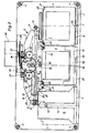
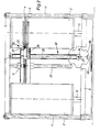
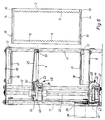
- Plate magazines 2 are arranged opposite one another laterally in the housing 1. In the space between the plate magazines 2 there is a transport device 3 which can be moved up and down for a plate holder 4 receiving a plate.
- a playback unit 5 with a turntable (not shown in detail), motor for rotating the turntable and playback head is fixed between and below the two opposite plate magazines 2 attached.
- the plate magazines 2 are constructed identically to one another and each have a multiplicity of receiving compartments 6 arranged one above the other for the storage of a corresponding number of plate holders 4 each receiving a plate.
- the plate holder 4 is in position in the receiving compartment 6 by at least one spring element 7 attached to the plate magazine 2 secured. In this position, the plate holder 4 is so far above the two possible pull-out sides of the plate magazine 2 that it can be gripped by a pull-out device 8 of the transport device 3.
- Each plate magazine 2 is interchangeably inserted into the housing 1 from the front of the housing 1.
- the housing 1 consists of a rectangular base plate 9 and a rectangular ceiling plate 10 located at a certain distance from it, which are connected to one another by connecting elements 11 arranged at the corners and designed as rods.
- the ceiling plate 10 is removable and the connecting elements 11 are interchangeable in length, so that plate magazines 2 of different heights can be used. Furthermore, a stabilizing element 12 designed as a rod extends between the base plate 9 and the ceiling plate 10 in order to increase the rigidity of the housing 1. On the inside of the base plate 9 and on the inside of the cover plate 10, guide rails 13 for each plate magazine 2 are arranged opposite one another, which correspond to a corresponding groove 14 in the bottom wall 15 and in the cover wall 16 of the plate magazine 2, respectively.
- a clip tongue 17 with the protruding clip nose 18 is molded into each guide rail 13, which, when the plate magazine 2 is inserted, engages in an associated opening 19 in the bottom wall 15 or in the ceiling wall 16 of the plate magazine 2.
- the plate holder 4 has a continuous recess 20 in the end region on its side facing the transport device 3.
- Each recess 20 is adjoined on the outside by a conveying nose 21, which is offset from the bottom halfway down the plate holder 4 and under which there is a free passage 22 to the recess 20.
- a gripper arm 23 of the pull-out device 8 of the transport device 3 can travel into one of the recesses 20 according to the position of the plate holder in one or the other plate magazine 2 through the passage 22.
- the gripping arm 21 can then be moved vertically in the superimposed recesses 20 of the plate magazine 4 until the gripping arm is behind the conveying nose 21 of the plate holder 4 with the selected plate.
- the gripper arm 23 then conveys the plate holder 4 to a support arm 25 attached to the housing 24 of the transport device 3 by appropriately actuating the pull-out device 8 due to its abutment on the transport nose 21, the travel path of the gripper arm 23 via a plate holder detection device 26 assigned to the transport device 3 is controlled that the disc holder 4 assumes a centering position defining the selected disc concentrically with the turntable of the playback unit 5.
- the transport device 3 then conveys the disc holder 4 to the playback unit 7, in which the information is then read from the disc. After the information has been read out, the plate with the plate holder 4 is conveyed back in an analogous manner by the transport device 3 into its associated receiving compartment 6. Then the transport device 3 moves into its starting position immediately above the playback unit 5, the starting position over one Sensor 27 is monitored.
- the gripper arm 23 is rigidly formed on a carriage 28, which can be moved back and forth on a support rod 29 arranged in the housing 24 of the transport device 3 by means of a drive 30. At the end, the support rod 29 carries a stop 31 for the slide 28.
- Four possible end positions I to IV of the slide 28 are shown in FIG. The end position I of the slide 28 is determined by the contact of the slide 28 on the right stop 31 of the support rod 29, in which the gripper arm 23 can be moved vertically in the superimposed recesses 20 of the right-hand plate magazine 4.
- the carriage 28 moves into the end position II, which is determined by the disc holder recognition device 26 and in which the disc holder 4 is aligned with the playback unit 5 . If, on the other hand, the gripper arm 23 located in the right plate magazine 2 assumes the position behind a free passage 22 of a plate holder 4, the carriage 28 moves into the end position III, in which the gripper arm 23 vertically in the recesses 20 of the plate holder 4 of the left plate magazine 2 lying one above the other is movable.
- the slide 28 can move back into the end position 1. If, on the other hand, the gripper arm 23 in the left-hand disk magazine 2 assumes a position behind the conveying nose 21 of a disk holder 4, the carriage 28 moves into the end position IV, which is determined by the disk holder detection device 26 and in which the disk holder 4 is aligned with the playback unit 5 is.
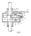
- the drive 33 comprises a toothed belt 35 which runs parallel to the support rod 32 and is guided over deflection rollers 34 and is connected to the housing 24 of the transport device 3 via a clamping bracket 36.
- the lower deflection roller 34 is seated on the shaft 37 of a reversible drive motor 38.
- the shaft 37 of the drive motor 38 also carries a code sheath 39 designed as an impeller, the blades of which run in a sensor 40 designed as a fork coupler for generating positioning pulses.
- the support rod 32 is rotatably supported in the base plate 9 and in the cover plate 10 and is connected below the base plate 9 via a slip clutch 43 and a worm gear 44 to a reversible drive motor 45.
- a code disk 46 designed as a marking disk is attached to the slip clutch 43 and runs through stationary sensors 47 designed as fork couplers for generating switching pulses for the drive motor 45. With the help of the code disk 46, the drive motor 45 is switched off and the respective end position of the slide 28 or the gripping arm 23 is monitored.
- On the support rod 32 is within the housing 24 of the transport device 3 Slidable, rotatable gear 49 is mounted, which meshes with two opposite fixed gears 50 which can be brought into engagement with a rack 51 attached to the slide 28 of the gripper arm 23. The back and forth movement of the carriage 28 is thus generated by a different rotational movement of the support rod 32.
- the plate holder detection device 26 comprises a spring-loaded mechanical sensor 52 which projects into the movement path of the plate holder 4 guided on a guide rail 53 of the transport device 3 fixed to the housing.
- the sensor 52 is slidably supported on the guide rail 53, a housing-fixed bracket 54 and the gear 49.
- a stop 57 protrudes into the passage 56, to which the pin 55 comes to rest on the right or left side when the sensor 22 is actuated by the plate holder, and thus the rotational movement of the gear wheel 49 and thus also the movement of the slide 28 in the end position II or IV stops, depending on which side the pin 55 strikes the stop 57.
- the pin 55 can move through the free passage 56 of the sensor, whereby the gear 49 is driven until the carriage 28 has reached the end position I or III, depending on the situation in which direction of rotation the gear 49 was driven.
- the carriage 28 is in the end position II, in which the pin 55 of the gear 49 rests on the left side on the stop 57 of the sensor 52.
- a further pin 55 becomes on the gearwheel 49 at the appropriate distance from the pin 55 'attached, which determines the end position IV of the carriage 28 by its right-sided abutment on the stop 57.
- the sensor 52 has on its upper side in the front area a web 58 on which a compression spring 59 is supported, the other end of which rests against a stop 60 fixed to the housing in the area of the support rod 32.
- the stop 60 is at a corresponding distance from a stop 66 fixed to the housing, against which the web 58 of the sensor 52 bears when the sensor 52 is in the unloaded state by the plate holder 4.
- the housing-fixed guide rail 53 of the transport device 3 is opposite a holding rail 61 for the plate holder 4 which is fastened to the free end of the support arm 25.
- the holding rail 61 is centrally associated with a spring element 62 designed as a U-shaped bracket, the legs 63 of which are inserted into recesses on the support arm 25 and the web has a bead 64 in the center, which in the centering position of the disc holder 4 to the playback unit 5 in a corresponding incision 65 engages the plate holder 4.
- the plate holder is immovably fixed in its centering position.
- the plate magazines 2 can be inserted into the housing 1 from above after the cover plate 10 has been removed.
- Each plate magazine 2 is provided on its top wall 16 with a foldable handle 67. Such interchangeability of the plate magazines 2 is particularly necessary when there is no more free space in the horizontal circumferential area of the housing 1.
Landscapes
- Automatic Disk Changers (AREA)
- Holding Or Fastening Of Disk On Rotational Shaft (AREA)
- Transition And Organic Metals Composition Catalysts For Addition Polymerization (AREA)
- Stereophonic System (AREA)
- Circuit For Audible Band Transducer (AREA)
- Optical Record Carriers And Manufacture Thereof (AREA)
- Developing Agents For Electrophotography (AREA)
- Packaging For Recording Disks (AREA)
- Holo Graphy (AREA)
Claims (28)
- Tourne-disque avec deux magasins à disques (2) se faisant face, qui comportent une pluralité de supports de disque (4) logeant chacun un disque, montés superposés dans des casiers de réception (6), et avec un dispositif de transport (3), déplaçable suivant le sens d'empilement des magasins à disques (2), pour l'échange d'un disque souhaité avec le support de disque (4) associé entre le casier de réception (6) et une unité de lecture (5), le dispositif de transport (3) comprenant un dispositif d'extraction (8), déplaçable horizontalement, comportant un chariot (28) avec un bras de préhension (23), caractérisé en ce que le dispositif d'extraction (8) ne comporte qu'un seul bras de préhension (23), relié rigidement avec le chariot (28), qui dessert deux magasins à disques (2) et est déplaçable horizontalement entre les magasins à disques et verticalement dans les magasins à disques, le bras de préhension (23) étant déplaçable verticalement de sa position de sélection prise dans l'un ou l'autre magasin à disques (2) dans des évidements superposés (20) des supports de disque (4) du magasin à disques respectif (2).
- Tourne-disque selon la revendication 1, caractérisé en ce que le bras de préhension (23) est déplaçable de sa position de sélection dans l'un ou l'autre magasin à disques (2), dans une position d'extraction en vue de l'extraction d'un support de disque déterminé (4), dans laquelle il est aligné avec un ergot de transport (21) se rattachant à l'évidement (20) du support de disque (4), disposé à mi-hauteur du support de disque (4).
- Tourne-disque selon la revendication 1 ou 2, caractérisé en ce que le bras de préhension (23) est déplaçable, par un dispositif de reconnaissance de support de disque (26) associé au dispositif de transport (3), dans une position de centrage fixant le disque sélectionné avec le support de disque (4) concentriquement au plateau tourne-disque de l'unité de lecture (5).
- Tourne-disque selon la revendication 3, caractérisé en ce qu'au dispositif de reconnaissance de support de disque (26) est associé un palpeur (52) de telle manière que lors d'une sollicitation du palpeur (52) par un support de disque (4) extrait d'un magasin à disques (2), le bras de préhension (23) relié rigidement au chariot (28) du dispositif d'extraction (8) passe dans une position de centrage fixant le disque sélectionné avec le support de disque (4) concentriquement au plateau tourne-disque de l'unité de lecture (5).
- Tourne-disque selon l'une des revendications 1 à 4, caractérisé en ce que le dispositif de transport (3) monté mobile à coulissement sur une tige porteuse (32) est déplaçable en montée et en descente par un entraînement à courroie (34, 35) avec moteur d'entraînement (38) dont le sens de rotation est réversible.
- Tourne-disque selon l'une des revendications 1 à 5, caractérisé en ce que le dispositif de transport (3) présente latéralement une encoche (41), qui entoure de façon mobile à glissement une tige de guidage (42) verticale, solidaire du bâti.
- Tourne-disque selon l'une des revendications 1 à 6, caractérisé en ce que le moteur d'entraînement (38) du dispositif de transport (3) porte sur son arbre (37) un disque à code (39) qui coopère avec un capteur (40) produisant des impulsions de position.
- Tourne-disque selon l'une des revendications 1 à 7, caractérisé en ce qu'au dispositif de transport (3) est associé un capteur (27) pour constater sa position de sortie, directement au-dessus de l'unité de lecture (5).
- Tourne-disque selon l'une des revendications 1 à 8, caractérisé en ce que la tige porteuse montée mobile à rotation (32) du dispositif de transport (3), est en liaison avec le moteur d'entraînement à sens de rotation réversible (45) par un accouplement à glissement (43) et la transmission (44), et en ce qu'à l'intérieur du dispositif de transport (3), la tige porteuse (32) porte une roue dentée (49) solidaire en rotation, déplaçable sur celle-ci, qui engrène avec au moins une roue dentée (50), qui est en prise avec une crémaillère (51) placée sur le chariot (28) du bras de préhension (23).
- Tourne-disque selon l'une des revendications 5 à 9, caractérisé en ce que la tige porteuse (32) est reliée fixement avec un disque à code (46), qui tourne à travers des capteurs stationnaires (47), pour produire des impulsions de coupure pour le moteur d'entraînement (45) de la tige porteuse (32).
- Tourne-disque selon la revendication 10, caractérisé en ce que le disque à code (46) est conformé en disque à trous ou disques à marquage.
- Tourne-disque selon l'une des revendications 3 à 11, caractérisé en ce que le dispositif de reconnaissance de support de disque (26) comprend le palpeur (52) mécanique guidé sous l'action d'un ressort dans le carter (24) du dispositif de transport (3), dépassant dans la trajectoire du support de disque (4), palpeur qui, dans le cas d'une sollicitation par le support de disque (4), limite le mouvement de rotation de la roue dentée (49) placée sur la tige de support (32).
- Tourne-disque selon la revendication 12, caractérisé en ce que sur la face supérieure de la roue dentée (49) placée sur la tige porteuse (32) est prévu un téton (55), qui à l'état non actionné du palpeur (52), est déplaçable à travers un passage (56), dans la face inférieure du palpeur (52) et qui, à l'état actionné du palpeur (52) dans la position de centrage du support de disque (4) par rapport à l'unité de lecture (5), s'applique contre une butée (57) pénétrant dans le passage (56).
- Tourne-disque selon la revendication 12 ou 13, caractérisé en ce que le palpeur (52) présente, sur sa face supérieure, dans la zone avant, une traverse (58), qui à l'état non actionné du palpeur (52), s'applique, sous l'action d'un ressort, contre une butée (66) solidaire du carter.
- Tourne-disque selon la revendication 14, caractérisé en ce qu'à la butée (66) solidaire du carter pour la traverse (58) du palpeur (52), fait face une butée (60) solidaire du carter, dans la région de la tige porteuse (32), contre laquelle prend appui un ressort de pression (59), qui s'applique avec son autre extrémité contre la traverse (58) du palpeur (52).
- Tourne-disque selon l'une des revendications 12 à 15, caractérisé en ce que le palpeur (52), guidé sur une fixation (54) passe, avec sa zone avant, sur un rail de guidage (53) solidaire du carter pour le support de disque (4).
- Tourne-disque selon l'une des revendications 12 à 16, caractérisé en ce que le carter (24) du dispositif de transport (3) comporte un bras porteur (25) avec un rail de maintien (61) situé à l'opposé du rail de guidage (53) solidaire du carter, pour le support de disque (4), au rail de maintien (61) étant associé au moins un élément à ressort (62), qui bloque le support de disque (4) dans sa position de centrage par rapport à l'unité de lecture (5).
- Tourne-disque selon la revendication 17, caractérisé en ce que l'élément à ressort (62) est moulé par injection sur le rail de maintien (61) et s'encastre dans une encoche correspondante (65) du support de disque (4).
- Tourne-disque selon la revendication 17, caractérisé en ce que l'élément à ressort (62) est constitué d'un étrier en U, dont les branches (63) sont insérées dans des enfoncements du bras porteur (25) et dont la traverse présente au milieu une moulure (64), qui s'engage dans une encoche (65) située sur le côté longitudinal correspondant du support de disque (4).
- Tourne-disque selon l'une des revendications 1 à 19, caractérisé en ce que chaque magasin à disques (2) inséré à la manière d'un tiroir dans un bâti associé (1), à partir du côté avant de ce bâti, est bloqué dans sa position par au moins une liaison amovible.
- Tourne-disque selon la revendication 20, caractérisé en ce que la liaison amovible entre le magasin à disques (2) et le bâti (1) est formée comme une liaison clipsée.
- Tourne-disque selon l'une des revendications 1 à 21, caractérisé en ce que le bâti (1) présente, pour le logement de chaque magasin à disques (2), deux rails de guidage (13) se faisant face, qui correspondent à une rainure correspondante (14) dans la paroi de fond (15) ou dans la paroi de couverture (16) du magasin à disques (2).
- Tourne-disque selon la revendication 22, caractérisé en ce que dans chaque rail de guidage (13) est formée une languette de clipsage (17) avec ergot de clipsage saillant (18), qui s'encastre dans un orifice associé (19) dans la paroi de fond (15) ou dans la paroi de couverture (16) du magasin à disques (2).
- Tourne-disque selon l'une des revendications 1 à 19, caractérisé en ce que les magasins à disques (2) sont insérés dans le bâti (1), de manière interchangeable verticalement, à partir du côté supérieur du bâti (1).
- Tourne-disque selon l'une des revendications 1 à 24, caractérisé en ce que le bâti (1) est constitué d'une plaque de fond (9) et d'une plaque de couverture (10) qui sont reliées uniquement entre elles par des éléments de liaison (11), la plaque de couverture (10) étant amovible et les éléments de liaison (11) étant de longueur échangeable.
- Tourne-disque selon la revendication 25, caractérisé en ce que les éléments de liaison (11) sont des tringles, des cornières, des profilés ou similaires.
- Tourne-disque selon les revendications 25 et 26, caractérisé en ce qu'entre les éléments de liaison (11) de la plaque de fond (9) et de la plaque de couverture (10) du bâti (1) sont prévus des éléments de revêtement.
- Tourne-disque selon l'une des revendications 1 à 27, caractérisé en ce qu'au moins un élément de stabilisation (12) est prévu entre la plaque de couverture (10) et la plaque de fond (9).
Priority Applications (1)
| Application Number | Priority Date | Filing Date | Title |
|---|---|---|---|
| EP97102195A EP0790612B1 (fr) | 1993-06-12 | 1994-06-06 | Lecteur de disques |
Applications Claiming Priority (3)
| Application Number | Priority Date | Filing Date | Title |
|---|---|---|---|
| DE4319551 | 1993-06-12 | ||
| DE4319551A DE4319551A1 (de) | 1993-06-12 | 1993-06-12 | Plattenabspielgerät |
| PCT/DE1994/000639 WO1994029861A1 (fr) | 1993-06-12 | 1994-06-06 | Tourne-disques |
Related Child Applications (2)
| Application Number | Title | Priority Date | Filing Date |
|---|---|---|---|
| EP97102195A Division EP0790612B1 (fr) | 1993-06-12 | 1994-06-06 | Lecteur de disques |
| EP97102195.1 Division-Into | 1997-02-12 |
Publications (2)
| Publication Number | Publication Date |
|---|---|
| EP0702826A1 EP0702826A1 (fr) | 1996-03-27 |
| EP0702826B1 true EP0702826B1 (fr) | 1997-08-13 |
Family
ID=6490234
Family Applications (2)
| Application Number | Title | Priority Date | Filing Date |
|---|---|---|---|
| EP94916888A Expired - Lifetime EP0702826B1 (fr) | 1993-06-12 | 1994-06-06 | Tourne-disques |
| EP97102195A Expired - Lifetime EP0790612B1 (fr) | 1993-06-12 | 1994-06-06 | Lecteur de disques |
Family Applications After (1)
| Application Number | Title | Priority Date | Filing Date |
|---|---|---|---|
| EP97102195A Expired - Lifetime EP0790612B1 (fr) | 1993-06-12 | 1994-06-06 | Lecteur de disques |
Country Status (6)
| Country | Link |
|---|---|
| US (1) | US5818802A (fr) |
| EP (2) | EP0702826B1 (fr) |
| JP (1) | JPH08511893A (fr) |
| AT (2) | ATE183013T1 (fr) |
| DE (3) | DE4319551A1 (fr) |
| WO (1) | WO1994029861A1 (fr) |
Families Citing this family (16)
| Publication number | Priority date | Publication date | Assignee | Title |
|---|---|---|---|---|
| DE4418116A1 (de) * | 1994-05-24 | 1995-11-30 | Nsm Ag | Wiedergabe- und/oder Aufzeichnungs- und/oder Ausgabegerät für als Informationsträger ausgebildete Platten |
| DE19651823A1 (de) * | 1996-12-13 | 1998-06-18 | Nsm Ag | Plattenwiedergabe- und/oder Aufzeichnungsgerät und Verfahren zur Positionierung der Platten-Transporteinrichtung desselben |
| DE19700741C2 (de) * | 1997-01-11 | 2000-02-03 | Grundig Ag | Magazin für magneto-optische Speichermedien für ein modulares Massenspeichersystem |
| JP3760024B2 (ja) * | 1997-06-16 | 2006-03-29 | 株式会社コダックデジタルプロダクトセンター | 記録媒体の保管装置 |
| US6246642B1 (en) * | 1999-04-13 | 2001-06-12 | Hewlett-Packard Company | Automated optical detection system and method |
| EP1096487B1 (fr) * | 1999-11-01 | 2003-06-04 | Cheung, Wing sang | Système de stockage de disques |
| DE60112043T2 (de) | 2000-02-08 | 2006-04-20 | Thomson Licensing S.A. | Behälter für optische platten , plattenteller und plattenspieler vom magazintyp |
| AU2001267248A1 (en) * | 2000-07-09 | 2002-01-21 | Brooks-Pri Automation Gmbh | Storage device, especially for the intermediate storage of test wafers |
| DE10361670B4 (de) | 2003-12-30 | 2009-08-06 | Mitsubishi Denki K.K. | Stator einer rotierenden elektrischen Maschine |
| US7707596B1 (en) * | 2005-07-14 | 2010-04-27 | Storage Technology Corporation | Queue hand |
| US7940609B2 (en) * | 2007-01-04 | 2011-05-10 | Datatronics Technology, Inc. | System for duplication of data onto disks |
| JP2012208983A (ja) * | 2011-03-30 | 2012-10-25 | Hitachi-Lg Data Storage Inc | 記録再生装置 |
| JP6074805B2 (ja) * | 2012-06-15 | 2017-02-08 | パナソニックIpマネジメント株式会社 | ディスク装置 |
| US9633686B1 (en) | 2016-02-17 | 2017-04-25 | International Business Machines Corporation | Disc storage cassettes |
| US10529371B1 (en) | 2018-10-29 | 2020-01-07 | International Business Machines Corporation | Actuator tip calibration for robotic optical storage system |
| US10600441B1 (en) * | 2018-12-07 | 2020-03-24 | International Business Machines Corporation | Disc gripper for storage discs |
Family Cites Families (18)
| Publication number | Priority date | Publication date | Assignee | Title |
|---|---|---|---|---|
| JPS4728752A (fr) * | 1970-12-29 | 1972-11-02 | ||
| JPS5573960A (en) * | 1978-11-29 | 1980-06-04 | Matsushita Electric Ind Co Ltd | Information offering system |
| AU578621B2 (en) * | 1983-08-31 | 1988-11-03 | Sony Corporation | Device for exchanging disks |
| GB2164781B (en) * | 1984-09-18 | 1989-04-19 | Sharp Kk | Disk storage and handling system for disk player |
| JPS62124662A (ja) * | 1985-11-25 | 1987-06-05 | Hitachi Ltd | 光デイスクの自動装填装置 |
| US4787074A (en) * | 1987-02-27 | 1988-11-22 | Eastman Kodak Company | Automated library for data storage disks |
| JPS6466862A (en) * | 1987-09-07 | 1989-03-13 | Toshiba Corp | Disk auto-changer device |
| JPH0197447U (fr) * | 1987-12-21 | 1989-06-28 | ||
| DE3922721A1 (de) * | 1988-10-19 | 1990-04-26 | Nsm Apparatebau Gmbh Kg | Plattenabspielgeraet |
| JPH02216661A (ja) * | 1989-02-16 | 1990-08-29 | Pioneer Electron Corp | マガジンチェンジャー付ディスクプレーヤ |
| US5539712A (en) * | 1989-10-17 | 1996-07-23 | Nsm Aktiengesellschaft | Lifting and lowering device for a record playback unit in a record playing device |
| JPH04143959A (ja) * | 1990-10-05 | 1992-05-18 | Mitsubishi Electric Corp | ディスク記憶装置 |
| US5123000A (en) * | 1990-10-24 | 1992-06-16 | International Data Engineering, Inc. | Optical disk cartridge handling apparatus |
| US5255251A (en) * | 1990-10-24 | 1993-10-19 | International Data Engineering, Inc. | Optical disc cartridge handling apparatus with removable magazine |
| DE4101693A1 (de) * | 1991-01-22 | 1992-07-23 | Nsm Ag | Plattenabspielgeraet |
| DE4105016C2 (de) * | 1991-02-19 | 1994-12-08 | Wurlitzer Gmbh | Plattenabspielgerät |
| US5267225A (en) * | 1991-02-26 | 1993-11-30 | Victor Company Of Japan, Ltd. | Automatic disc player system loaded with a multiplicity of selectable discs |
| JP2708054B2 (ja) * | 1992-08-31 | 1998-02-04 | 日本ビクター株式会社 | 記録媒体の再生装置 |
-
1993
- 1993-06-12 DE DE4319551A patent/DE4319551A1/de not_active Withdrawn
-
1994
- 1994-06-06 DE DE59408597T patent/DE59408597D1/de not_active Expired - Fee Related
- 1994-06-06 AT AT97102195T patent/ATE183013T1/de not_active IP Right Cessation
- 1994-06-06 JP JP7501187A patent/JPH08511893A/ja active Pending
- 1994-06-06 AT AT94916888T patent/ATE156926T1/de not_active IP Right Cessation
- 1994-06-06 EP EP94916888A patent/EP0702826B1/fr not_active Expired - Lifetime
- 1994-06-06 DE DE59403743T patent/DE59403743D1/de not_active Expired - Fee Related
- 1994-06-06 WO PCT/DE1994/000639 patent/WO1994029861A1/fr not_active Ceased
- 1994-06-06 US US08/553,673 patent/US5818802A/en not_active Expired - Fee Related
- 1994-06-06 EP EP97102195A patent/EP0790612B1/fr not_active Expired - Lifetime
Also Published As
| Publication number | Publication date |
|---|---|
| ATE156926T1 (de) | 1997-08-15 |
| ATE183013T1 (de) | 1999-08-15 |
| EP0702826A1 (fr) | 1996-03-27 |
| WO1994029861A1 (fr) | 1994-12-22 |
| DE4319551A1 (de) | 1994-12-15 |
| EP0790612B1 (fr) | 1999-08-04 |
| JPH08511893A (ja) | 1996-12-10 |
| DE59403743D1 (de) | 1997-09-18 |
| DE59408597D1 (de) | 1999-09-09 |
| US5818802A (en) | 1998-10-06 |
| EP0790612A2 (fr) | 1997-08-20 |
| EP0790612A3 (fr) | 1998-05-27 |
Similar Documents
| Publication | Publication Date | Title |
|---|---|---|
| EP0702826B1 (fr) | Tourne-disques | |
| EP0439483B1 (fr) | Tourne-diques | |
| DE4105016C2 (de) | Plattenabspielgerät | |
| DE3818502C2 (fr) | ||
| DE3645199C2 (fr) | ||
| DE4205912C2 (de) | Automatisches Disk-Abspielgerät | |
| DE3742096A1 (de) | Werkzeugmagazin | |
| DE3914129C2 (fr) | ||
| EP0568562B1 (fr) | Juke-box | |
| DE69825663T2 (de) | Datenkassettenverriegelungs- und entriegelungssystem | |
| DE4418116A1 (de) | Wiedergabe- und/oder Aufzeichnungs- und/oder Ausgabegerät für als Informationsträger ausgebildete Platten | |
| DE3886926T2 (de) | Vorrichtung zur einstellung des drehachsabstandes für eine bandwickelvorrichtung für verschiedene kassettengrössen. | |
| DE3914128A1 (de) | Vielfachmagazin-plattenspieler | |
| EP0002255B1 (fr) | Appareil enregistreur | |
| DE3044965C2 (de) | Einrichtung in einem Plattenspieler zur Identifizierung der Abspielseite der Platte | |
| DE102004041283B3 (de) | Vorrichtung zum Speichern von Daten auf in Kassetten aufgenommenen Datenträgern | |
| DE19623124A1 (de) | Vorrichtung zur Entnahme eines Plattenhalters aus und/oder Rückgabe an ein auswechselbares Magazin | |
| EP0495827B1 (fr) | Changeur de cassettes | |
| DE4140234A1 (de) | Plattenabspielgeraet | |
| EP0780016B1 (fr) | Lecteur de disques | |
| DE2212233C2 (de) | Anordnung mit zumindest zwei zusammenwirkenden Aufnahme- und/oder Wiedergabegeraeten fuer in Kassetten befindliche Aufzeichnungsbaender | |
| DE10055624C2 (de) | Bibliothek für Kassetten eines Datenspeicherbandes | |
| DE3731702C1 (en) | Container for flat information carriers | |
| DE1817857C3 (de) | Speicheranlage für in mehreren Reihen abgestellte flache Gegenstände | |
| EP0308606A1 (fr) | Appareil avec dispositif de chargement/éjection de cassette |
Legal Events
| Date | Code | Title | Description |
|---|---|---|---|
| PUAI | Public reference made under article 153(3) epc to a published international application that has entered the european phase |
Free format text: ORIGINAL CODE: 0009012 |
|
| 17P | Request for examination filed |
Effective date: 19951201 |
|
| AK | Designated contracting states |
Kind code of ref document: A1 Designated state(s): AT BE CH DE ES FR GB IT LI |
|
| 17Q | First examination report despatched |
Effective date: 19960425 |
|
| GRAG | Despatch of communication of intention to grant |
Free format text: ORIGINAL CODE: EPIDOS AGRA |
|
| GRAH | Despatch of communication of intention to grant a patent |
Free format text: ORIGINAL CODE: EPIDOS IGRA |
|
| GRAH | Despatch of communication of intention to grant a patent |
Free format text: ORIGINAL CODE: EPIDOS IGRA |
|
| GRAA | (expected) grant |
Free format text: ORIGINAL CODE: 0009210 |
|
| AK | Designated contracting states |
Kind code of ref document: B1 Designated state(s): AT BE CH DE ES FR GB IT LI |
|
| DX | Miscellaneous (deleted) | ||
| PG25 | Lapsed in a contracting state [announced via postgrant information from national office to epo] |
Ref country code: IT Free format text: LAPSE BECAUSE OF FAILURE TO SUBMIT A TRANSLATION OF THE DESCRIPTION OR TO PAY THE FEE WITHIN THE PRE;WARNING: LAPSES OF ITALIAN PATENTS WITH EFFECTIVE DATE BEFORE 2007 MAY HAVE OCCURRED AT ANY TIME BEFORE 2007. THE CORRECT EFFECTIVE DATE MAY BE DIFFERENT FROM THE ONE RECORDED.SCRIBED TIME-LIMIT Effective date: 19970813 Ref country code: ES Free format text: THE PATENT HAS BEEN ANNULLED BY A DECISION OF A NATIONAL AUTHORITY Effective date: 19970813 |
|
| REF | Corresponds to: |
Ref document number: 156926 Country of ref document: AT Date of ref document: 19970815 Kind code of ref document: T |
|
| REG | Reference to a national code |
Ref country code: CH Ref legal event code: EP |
|
| REF | Corresponds to: |
Ref document number: 59403743 Country of ref document: DE Date of ref document: 19970918 |
|
| ET | Fr: translation filed | ||
| GBT | Gb: translation of ep patent filed (gb section 77(6)(a)/1977) |
Effective date: 19971110 |
|
| PG25 | Lapsed in a contracting state [announced via postgrant information from national office to epo] |
Ref country code: AT Free format text: LAPSE BECAUSE OF NON-PAYMENT OF DUE FEES Effective date: 19980606 |
|
| PLBE | No opposition filed within time limit |
Free format text: ORIGINAL CODE: 0009261 |
|
| STAA | Information on the status of an ep patent application or granted ep patent |
Free format text: STATUS: NO OPPOSITION FILED WITHIN TIME LIMIT |
|
| PG25 | Lapsed in a contracting state [announced via postgrant information from national office to epo] |
Ref country code: LI Free format text: LAPSE BECAUSE OF NON-PAYMENT OF DUE FEES Effective date: 19980630 Ref country code: CH Free format text: LAPSE BECAUSE OF NON-PAYMENT OF DUE FEES Effective date: 19980630 Ref country code: BE Free format text: LAPSE BECAUSE OF NON-PAYMENT OF DUE FEES Effective date: 19980630 |
|
| 26N | No opposition filed | ||
| BERE | Be: lapsed |
Owner name: NSM A.G. Effective date: 19980630 |
|
| REG | Reference to a national code |
Ref country code: CH Ref legal event code: PL |
|
| PGFP | Annual fee paid to national office [announced via postgrant information from national office to epo] |
Ref country code: DE Payment date: 20000607 Year of fee payment: 7 |
|
| PGFP | Annual fee paid to national office [announced via postgrant information from national office to epo] |
Ref country code: GB Payment date: 20010601 Year of fee payment: 8 |
|
| PGFP | Annual fee paid to national office [announced via postgrant information from national office to epo] |
Ref country code: FR Payment date: 20010618 Year of fee payment: 8 |
|
| REG | Reference to a national code |
Ref country code: GB Ref legal event code: IF02 |
|
| PG25 | Lapsed in a contracting state [announced via postgrant information from national office to epo] |
Ref country code: DE Free format text: LAPSE BECAUSE OF NON-PAYMENT OF DUE FEES Effective date: 20020403 |
|
| PG25 | Lapsed in a contracting state [announced via postgrant information from national office to epo] |
Ref country code: GB Free format text: LAPSE BECAUSE OF NON-PAYMENT OF DUE FEES Effective date: 20020606 |
|
| GBPC | Gb: european patent ceased through non-payment of renewal fee |
Effective date: 20020606 |
|
| PG25 | Lapsed in a contracting state [announced via postgrant information from national office to epo] |
Ref country code: FR Free format text: LAPSE BECAUSE OF NON-PAYMENT OF DUE FEES Effective date: 20030228 |
|
| REG | Reference to a national code |
Ref country code: FR Ref legal event code: ST |