EP0702915A2 - Beschlag zur einstellbaren Festlegung einer Frontblende - Google Patents
Beschlag zur einstellbaren Festlegung einer Frontblende Download PDFInfo
- Publication number
- EP0702915A2 EP0702915A2 EP95111675A EP95111675A EP0702915A2 EP 0702915 A2 EP0702915 A2 EP 0702915A2 EP 95111675 A EP95111675 A EP 95111675A EP 95111675 A EP95111675 A EP 95111675A EP 0702915 A2 EP0702915 A2 EP 0702915A2
- Authority
- EP
- European Patent Office
- Prior art keywords
- front panel
- fitting according
- supporting parts
- arm
- fitting
- Prior art date
- Legal status (The legal status is an assumption and is not a legal conclusion. Google has not performed a legal analysis and makes no representation as to the accuracy of the status listed.)
- Granted
Links
- 239000003381 stabilizer Substances 0.000 claims description 3
- 230000000694 effects Effects 0.000 description 2
- 230000001419 dependent effect Effects 0.000 description 1
- 238000006073 displacement reaction Methods 0.000 description 1
- 238000003780 insertion Methods 0.000 description 1
- 230000037431 insertion Effects 0.000 description 1
Images



Classifications
-
- A—HUMAN NECESSITIES
- A47—FURNITURE; DOMESTIC ARTICLES OR APPLIANCES; COFFEE MILLS; SPICE MILLS; SUCTION CLEANERS IN GENERAL
- A47B—TABLES; DESKS; OFFICE FURNITURE; CABINETS; DRAWERS; GENERAL DETAILS OF FURNITURE
- A47B88/00—Drawers for tables, cabinets or like furniture; Guides for drawers
- A47B88/90—Constructional details of drawers
- A47B88/944—Drawers characterised by the front panel
- A47B88/95—Drawers characterised by the front panel characterised by connection means for the front panel
- A47B88/956—Drawers characterised by the front panel characterised by connection means for the front panel for enabling adjustment of the front panel
-
- A—HUMAN NECESSITIES
- A47—FURNITURE; DOMESTIC ARTICLES OR APPLIANCES; COFFEE MILLS; SPICE MILLS; SUCTION CLEANERS IN GENERAL
- A47B—TABLES; DESKS; OFFICE FURNITURE; CABINETS; DRAWERS; GENERAL DETAILS OF FURNITURE
- A47B88/00—Drawers for tables, cabinets or like furniture; Guides for drawers
- A47B88/90—Constructional details of drawers
- A47B88/944—Drawers characterised by the front panel
- A47B88/95—Drawers characterised by the front panel characterised by connection means for the front panel
- A47B2088/951—Drawers characterised by the front panel characterised by connection means for the front panel having male and female interlocking parts
-
- A—HUMAN NECESSITIES
- A47—FURNITURE; DOMESTIC ARTICLES OR APPLIANCES; COFFEE MILLS; SPICE MILLS; SUCTION CLEANERS IN GENERAL
- A47B—TABLES; DESKS; OFFICE FURNITURE; CABINETS; DRAWERS; GENERAL DETAILS OF FURNITURE
- A47B2210/00—General construction of drawers, guides and guide devices
- A47B2210/0002—Guide construction for drawers
- A47B2210/0029—Guide bearing means
- A47B2210/0032—Balls
-
- A—HUMAN NECESSITIES
- A47—FURNITURE; DOMESTIC ARTICLES OR APPLIANCES; COFFEE MILLS; SPICE MILLS; SUCTION CLEANERS IN GENERAL
- A47B—TABLES; DESKS; OFFICE FURNITURE; CABINETS; DRAWERS; GENERAL DETAILS OF FURNITURE
- A47B2210/00—General construction of drawers, guides and guide devices
- A47B2210/0002—Guide construction for drawers
- A47B2210/0051—Guide position
- A47B2210/0059—Guide located at the side of the drawer
-
- A—HUMAN NECESSITIES
- A47—FURNITURE; DOMESTIC ARTICLES OR APPLIANCES; COFFEE MILLS; SPICE MILLS; SUCTION CLEANERS IN GENERAL
- A47B—TABLES; DESKS; OFFICE FURNITURE; CABINETS; DRAWERS; GENERAL DETAILS OF FURNITURE
- A47B2210/00—General construction of drawers, guides and guide devices
- A47B2210/02—Drawers with hollow lateral walls in two parts
-
- A—HUMAN NECESSITIES
- A47—FURNITURE; DOMESTIC ARTICLES OR APPLIANCES; COFFEE MILLS; SPICE MILLS; SUCTION CLEANERS IN GENERAL
- A47B—TABLES; DESKS; OFFICE FURNITURE; CABINETS; DRAWERS; GENERAL DETAILS OF FURNITURE
- A47B88/00—Drawers for tables, cabinets or like furniture; Guides for drawers
- A47B88/90—Constructional details of drawers
- A47B88/919—Accessories or additional elements for drawers, e.g. drawer lighting
- A47B88/931—Rails or rods mounted above the drawer walls, e.g. for stabilisation of the drawer or for suspension of the content
Definitions
- the present invention relates to a fitting for the adjustable fixing of a front panel of a furniture pull-out part guided in guide rails, comprising two supporting parts and two front panel holders, the supporting parts being fixed to the ends of the guide rails on the front panel side and the front panel holder being attachable to the front panel and being connected to the supporting parts.
- the invention has for its object to provide a fitting of the generic type that is completely independent of the side walls or lateral double walls of an insert of the furniture pull-out part.
- front panel holder are indirectly connected to the supporting parts via intermediate pieces, that the intermediate pieces are pivotable relative to the supporting parts and relative to the front panel holders about vertical axes forming the corner points of a parallelogram and are height-adjustable relative to the supporting parts.
- Such a fitting can be realized regardless of the design of the furniture pull-out part and has no effect on the design of the side walls of the furniture pull-out part.
- Such a fitting is particularly suitable for furniture pull-out parts with lateral double walls, since these lateral double walls can completely hide the fitting parts arranged on the left and right sides.
- a furniture pull-out part 1 which has guide rails 2 on both longitudinal sides, on which a shell or box-like insert 3 rests and which is closed on the front by a front panel 4.
- a circumferential railing 5 is arranged above the insert 3.
- FIG. 2 also shows the front panel 4 and, in a highly abstract form, a fitting for the adjustable fixing of the front panel 4 relative to the guide rails 2.
- the fitting comprises two support parts 6, two front panel holders 7 and two intermediate pieces 8, these aforementioned parts each forming a structural unit and each being arranged in the region of the two guide rails 2.
- the supporting parts 6 are each firmly connected to the guide rails 2, for example via locking lugs 60, as indicated in FIG. 3.
- the support parts 6 can also be connected to the guide rails 2 in any other type of fastening.
- the front panel holder 7 are each attached to the front panel 4 at a distance from the two guide rails 2.
- the type of fastening is freely selectable and of minor importance for the present invention.
- Each intermediate piece 8 is pivotally connected to the support part 6 assigned to it as well as to the associated front panel holder 7, specifically about vertical axes 9 and 10 which, as FIG. 2 clearly shows, form the corner points of a parallelogram.
- the intermediate pieces 8 are mounted on a pin 11 relative to the supporting parts 6.
- the front panel holder 7 have hinge pin-like bolts 12 which engage in correspondingly designed bearing recesses 13 of the respective intermediate piece 8.
- an adjusting screw 14 which is screwed into this intermediate piece within an intermediate piece - optionally on the left or on the right side of the furniture pull-out part 1 and rests with its end faces on two side walls 15 of the supporting part 6.
- This set screw 14, which can be actuated by means of a corresponding tool by means of preferably slot-like openings 16 within the walls 15, the respective intermediate piece 8 can be displaced horizontally relative to the support part 6 fastened to the guide rail 2. Because of the parallelogram-like connection, the front panel 4 is shifted parallel to the left or right depending on the direction of rotation of the adjusting screw 14, so that the front panel can be adjusted properly in this respect.
- a height adjustment screw 17 is provided in both intermediate pieces 8 in this case.
- This height adjustment screw 17 is rotatably mounted within the respective intermediate piece 8, but axially but non-displaceably, and is screwed with its threaded region into a threaded insert 18, which is located within the stationary supporting part 6.
- actuating one or both of these height adjustment screws 17, the front panel is raised or lowered in the area in which the respective height adjustment screw 17 is operated.
- the height adjustment screws 17 are provided in the area of their head 19 with an annular groove 20 into which a bow spring 21 engages. This bow spring 21 is fixed within a transverse slot 22 of the intermediate piece 8 in the axial direction of the height adjustment screw 17 and thus also the height adjustment screw 17 itself.
- the height adjustment screw 17 acts as an adjusting spindle and raises or lowers the respective intermediate piece 8 when it is actuated, and although relative to the supporting part 6, which can be designated as stationary.
- each support part 6 resilient retaining tab 23 is formed, which is provided at its free end with a receiving fork 24.
- a locking pin 25 integrally formed on the respective intermediate piece 8 engages in this receiving fork 24.
- the retaining tabs 23 of the support parts 6 run radially towards the bolts 12 and the distance between the two retaining tabs 23 corresponds exactly to the spacing of the bolts 12 of the front panel holder 7 mounted on the front panel 4 predetermined distance from each other secured by the spring action of the retaining tabs 23, so that the hanging of the front panel 4 by means of the front panel holder 7 in the intermediate pieces 8 is facilitated.
- An adjustment of these intermediate pieces 4 via the adjusting screw 14, however, is possible at any time due to the resilient effect of the retaining tabs 23.
- each front panel holder 7 is secured against unintentional lifting after the insertion of its bolts 12 into the bearing recesses 13 of the intermediate pieces 3 provided for this purpose, which engages under the upper bearing in the exemplary embodiment shown and is supported on it. Deviating from this, it is of course also conceivable to implement a latching between each front panel holder 7 and the associated intermediate piece 8 at a different location.
- the latching can be deliberately released and then the front panel 4 can be removed comfortably.
- the support parts 6 of the fitting are advantageously also used to accommodate a self-closing device 30 for the furniture pull-out part 1.
- This self-retracting device 30 consists essentially of a spring-loaded lever 31 which is rotatably mounted in the respective support part 6 and which cooperates with an actuating pin 32 fixed on the guide rail 2 shortly before the furniture insert part 1 is finally inserted, ie the lever 31 becomes short by the actuating pin 32 actuated before the final retraction and due to the spring loading, the furniture pull-out part is now finally pulled into its closed position.
- FIGS. 9 to 11 show an exemplary embodiment of the invention, the basic structure of which corresponds to the exemplary embodiments described above.
- the fitting according to FIGS. 9 to 11 has been further developed so that the right-angled position between the guide rails 2 on the one hand and one mounted front panel 4, on the other hand, is also secured when an insert part, usually coupled to the guide rails 2, is removed in the form of a shell or a box.
- each support part 6 has at least one front panel stabilizer in the form of a bracket 35 which extends in the direction of the front panel holder 7 and has a support surface 36 for the front panel 4 at its free end.
- the fitting for fixing the front panel 4 comprises two supporting parts 6, two front panel holders 7 and two intermediate pieces 8, these aforementioned parts each forming a structural unit and being arranged in the region of the two guide rails 2.
- a fitting consisting of the aforementioned components is connected to each guide rail 2.
- the support parts 6 are each firmly connected to the guide rails 2.
- the front panel holder 7 are each fixed to the front panel 4 at a distance from the two guide rails 2.
- the respective intermediate piece 8 is pivotally connected to the support part 6 assigned to it as well as to the front panel holder 7 assigned to it, specifically about vertical axes 9 and 10, which form the corner points of a parallelogram.
- the front panel 4 can be aligned and adjusted via the fittings using known and therefore not shown adjustment devices.
- the structure consisting of the guide rails 2 and the front panel 4 becomes inherently unstable, i.e. with one-sided tension or pressure on the front panel 4, this front panel 4 can be inclined within certain limits relative to the guide rails 2.
- the supporting parts 6 are each equipped with at least one front panel stabilizer in the form of a boom 35.
- These arms 35 which are either made in one piece with the support part 6 or are preferably detachably connected to this support part 6, extend in the direction of the front panel holder 7 to the inside of the front panel 4 and lie with their free end faces Ends, each of which forms a support surface 36 for the front panel 4, on this front panel 4.
- the boom 35 can be fork-shaped and enclose the intermediate piece 8 between it with its two legs.
- the cantilevers 35 can have an angled web 37 enlarging the supporting surface at their front ends.
- FIG. 10 shows very clearly that the arms 35 are provided with recesses 38 and notches 39, which bring about a relatively high spring elasticity of the arms 35.
Landscapes
- Drawers Of Furniture (AREA)
- Joining Of Building Structures In Genera (AREA)
- Assembled Shelves (AREA)
- Connection Of Plates (AREA)
- Vehicle Step Arrangements And Article Storage (AREA)
- Fittings On The Vehicle Exterior For Carrying Loads, And Devices For Holding Or Mounting Articles (AREA)
- Body Structure For Vehicles (AREA)
- Casings For Electric Apparatus (AREA)
- Finishing Walls (AREA)
Abstract
Description
- Die vorliegende Erfindung betrifft einen Beschlag zur einstellbaren Festlegung einer Frontblende eines in Führungsschienen geführten Möbelauszugsteiles, umfassend zwei Tragteile und zwei Frontblendenhalter, wobei die Tragteile an den frontblendenseitigen Enden der Führungsschienen festgelegt und die Frontblendenhalter an der Frontblende befestigbar sowie mit den Tragteilen verbunden sind.
- Der Erfindung liegt die Aufgabe zugrunde, einen Beschlag der gattungsgemäßen Art zu schaffen, der vollkommen unabhängig von den Seitenwandungen oder von seitlichen Doppelwandungen eines Einsatzes des Möbelauszugsteiles ist.
- Diese Aufgabe wird erfindungsgemäß dadurch gelöst, daß die Frontblendenhalter über Zwischenstücke mittelbar mit den Tragteilen verbunden sind, daß die Zwischenstücke gegenüber den Tragteilen und gegenüber den Frontblendenhaltern um vertikale, die Eckpunkte eines Parallelogrammes bildende Achsen schwenkbar und gegenüber den Tragteilen höhenverstellbar sind.
- Ein derartiger Beschlag ist unabhängig von der Gestaltung des Möbelauszugsteiles im übrigen zu verwirklichen und hat keinerlei Auswirkungen auf die Gestaltung der Seitenwandungen des Möbelauszugsteiles.
- Insbesondere eignet sich ein derartiger Beschlag für Möbelauszugsteile mit seitlichen Doppelwandungen, da diese seitlichen Doppelwandungen die links- und rechtsseitig angeordneten Beschlagteile vollkommen verdecken können.
- Weitere Merkmale der Erfindung sind Gegenstand von Unteransprüchen.
- In den beigefügten Zeichnungen sind Ausführungsbeispiele der Erfindung dargestellt, die im Folgenden näher beschrieben werden. Es zeigen:
- Fig. 1
- eine perspektivische Darstellung eines Möbelauszugsteiles,
- Fig. 2
- eine schematisch dargestellte Draufsicht auf die Führungsschienen sowie die gegenüber den Führungsschienen justierbare Frontblende des Möbelauszugsteiles nach Figur 1,
- Fig. 3
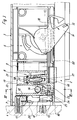
- den Verbindungsbereich der Möbelfrontblende gegenüber den vorderen Enden der Führungsschienen im Schnitt,
- Fig. 4
- eine Ansicht in Richtung des Pfeiles IV in Figur 3,
- Fig. 5
- eine Teilansicht in Richtung des Pfeiles V in Figur 3,
- Fig. 6
- einen Schnitt nach der Linie VI/VI in Figur 3,
- Fig. 7
- einen Schnitt durch ein Zwischenstück der Justiereinrichtung,
- Fig. 8
- eine Draufsicht in Richtung des Pfeiles VIII in Figur 7, dargestellt mit einem in das Zwischenstück eingesetzten Frontblendenhalter,
- Fig. 9
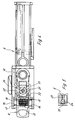
- eine schematisch dargestellte Draufsicht auf die Führungsschienen sowie die gegenüber den Führungsschienen justierbare Frontblende eines Möbelauszugsteiles nach einem weiteren Ausführungsbeispiel der Erfindung,
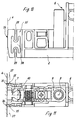
- Fig. 10
- eine vereinfachte Teilansicht in Richtung des Pfeiles X in Fig. 9,
- Fig. 11
- eine Draufsicht auf den Verbindungsbereich zwischen einer Führungsschiene und einer Frontblende nach den Figuren 9 und 10, teilweise im Schnitt dargestellt.
- In Figur 1 ist ein Möbelauszugsteil 1 dargestellt, welches an beiden Längsseiten Führungsschienen 2 aufweist, auf denen ein schalen- oder kastenartiger Einsatz 3 ruht und der vorderseitig durch eine Frontblende 4 abgeschlossen ist. Oberhalb des Einsatzes 3 ist eine umlaufende Reling 5 angeordnet.
- In der schematischen Draufsicht nach Figur 2 sind die beiden seitlichen Führungsschienen 2 gezeigt, außerdem zeigt Figur 2 die Frontblende 4 sowie in stark abstrahierter Form einen Beschlag zur einstellbaren Festlegung der Frontblende 4 gegenüber den Führungsschienen 2.
- Der Beschlag umfaßt zwei Tragteile 6, zwei Frontblendenhalter 7 sowie zwei Zwischenstücke 8, wobei diese vorgenannten Teile jeweils eine Baueinheit bilden und jeweils im Bereich der beiden Führungsschienen 2 angeordnet sind.
- Die Tragteile 6 sind jeweils fest mit den Führungsschienen 2 verbunden, beispielsweise über Rastnasen 60, wie in Figur 3 angedeutet. Die Tragteile 6 können aber auch in jeder beliebigen anderen Befestigungsart mit den Führungsschienen 2 verbunden sein.
- Die Frontblendenhalter 7 sind jeweils im Abstand der beiden Führungsschienen 2 zueinander an der Frontblende 4 befestigt. Auch hier ist die Befestigungsart frei wählbar und für die vorliegende Erfindung von untergeordneter Bedeutung.
- Jedes Zwischenstück 8 ist mit dem ihm jeweils zugeordneten Tragteil 6 ebenso wie mit dem zugeordneten Frontblendenhalter 7 schwenkbar verbunden, und zwar um vertikale Achsen 9 und 10, die, wie Figur 2 deutlich zeigt, die Eckpunkte eines Parallelogrammes bilden.
- Die Zwischenstücke 8 sind gegenüber den Tragteilen 6 auf einen Zapfen 11 gelagert. Die Frontblendenhalter 7 weisen scharnierzapfenähnliche Bolzen 12 auf, die in entsprechend gestaltete Lagerausnehmungen 13 des jeweiligen Zwischenstückes 8 eingreifen.
- Dies bedeutet, daß die Frontblende 4 über die Zwischenstücke 8 mittelbar mit den Tragteilen 6 verbunden ist.
- Aufgrund der Tatsache, daß die Zwischenstücke 8 um die erwähnten Achsen 9 und 10 verschwenkbar sind, ist eine Ausrichtung der Frontblende 4 im Sinne einer horizontalen Verschiebung möglich.
- Dies wird erreicht durch eine Stellschraube 14, die innerhalb eines Zwischenstückes - wahlweise auf der linken oder auf der rechten Seite des Möbelauszugsteiles 1 - in dieses Zwischenstück eingeschraubt ist und mit ihren kopfseitigen Stirnflächen an zwei seitlichen Wandungen 15 des Tragteiles 6 anliegt. Diese Stellschraube 14, die durch vorzugsweise schlitzartige Durchbrechnungen 16 innerhalb der Wandungen 15 über ein entsprechendes Werkzeug betätigbar ist, kann das betreffende Zwischenstück 8 gegenüber dem an der Führungsschiene 2 befestigten Tragteil 6 horizontal verschoben werden. Aufgrund der parallelogrammartigen Verbindung wird dabei die Frontblende 4 je nach Drehrichtung der Verstellschraube 14 nach links oder rechts parallel verschoben, so daß eine in dieser Hinsicht einwandfreie Justiermöglichkeit der Frontblende gewährleistet ist.
- Um eine Höhenverstellung der Frontblende 4 zu ermöglichen, ist - in diesem Falle in beiden Zwischenstücken 8 - jeweils eine Höhenverstellschraube 17 vorgesehen. Diese Höhenverstellschraube 17 ist innerhalb des jeweiligen Zwischenstückes 8 drehbar, axial aber unverschiebbar gelagert und mit ihrem Gewindebereich in einen Gewindeeinsatz 18 eingeschraubt, der sich innerhalb des ortsfesten Tragteiles 6 befindet. Durch Betätigung einer oder beider dieser Höhenverstellschrauben 17 wird ein Anheben oder Absenken der Frontblende in dem Bereich bewirkt, in dem die jeweilige Höhenverstellschraube 17 betätigt wird.
- Die Höhenverstellschrauben 17 sind im Bereich ihres Kopfes 19 mit einer Ringnut 20 versehen, in die eine Bügelfeder 21 eingreift. Diese Bügelfeder 21 ist innerhalb eines Querschlitzes 22 des Zwischenstückes 8 in axialer Richtung der Höhenverstellschraube 17 festgelegt und damit auch die Höhenverstellschraube 17 selbst. Somit wirkt die Höhenverstellschraube 17 wie eine Verstellspindel und hebt bei ihrer Betätigung das jeweilige Zwischenstück 8 an oder senkt dieses ab, und zwar relativ zum als ortsfest zu bezeichnenden Tragteil 6.
- Somit ist auch eine Höhenjustierung der Frontblende 4 ohne Schwierigkeiten exakt durchführbar.
- Um sicherzustellen, daß die beiden Lageraufnahmen 13 zur Aufnahme der Bolzen 12 der Frontblendenhalter 7 bei der Montage exakt den gleichen Achsabstand zueinander aufweisen wie die erwähnten Bolzen 22, ist an jedem Tragteil 6 eine horizontal federnde Haltelasche 23 angeformt, die an ihrem freien Ende mit einer Aufnahmegabel 24 versehen ist. In diese Aufnahmegabel 24 greift ein am jeweiligen Zwischenstück 8 angeformter Arretierungszapfen 25 ein.
- Die Haltelaschen 23 der Tragteile 6 laufen radial auf die Bolzen 12 zu und der Abstand der beiden Haltelaschen 23 zueinander entspricht exakt dem Abstand der Bolzen 12 der an der Frontblende 4 montierten Frontblendenhalter 7. Durch die Haltelaschen 23 werden die beiden schwenkbar gelagerten Zwischenstücke 8 in ihrem vorgegebenen Abstand zueinander durch die Federwirkung der Haltelaschen 23 gesichert, so daß das Einhängen der Frontblende 4 mittels der Frontblendenhalter 7 in die Zwischenstücke 8 erleichtert wird. Eine Verstellung dieser Zwischenstücke 4 über die Stellschraube 14 ist hingegen aufgrund der federnden Wirkung der Haltelaschen 23 jederzeit möglich.
- Wie Figur 3 sehr deutlich macht, ist jeder Frontblendenhalter 7 nach dem Einsetzen seiner Bolzen 12 in die dafür vorgesehenen Lagerausnehmungen 13 der Zwischenstücke 3 gegenüber unbeabsichtigtes Abheben gesichert durch einen Rasthebel 26, der im dargestellten Ausführungsbeispiel das obere Lager untergreift und sich an diesem abstützt. Abweichend hiervon ist es natürlich auch denkbar, eine Verrastung zwischen jedem Frontblendenhalter 7 und dem zugeordneten Zwischenstück 8 an einer anderen Stelle zu verwirklichen.
- Bei einer erforderlich werdenden Demontage kann die Verrastung bewußt aufgehoben und dann die Frontblende 4 bequem abgenommen werden.
- Wie Figur 3 deutlich zeigt, sind die Tragteile 6 des Beschlages vorteilhafterweise auch noch dazu genutzt, eine Selbsteinzugsvorrichtung 30 für das Möbelauszugsteil 1 aufzunehmen. Diese Selbsteinzugsvorrichtung 30 besteht im wesentlichen aus einem federbelasteten, im jeweiligen Tragteil 6 drehbar gelagerten Hebel 31, der kurz vor dem endgültigen Einschieben des Möbelauszugsteiles 1 mit einem an der Führungsschiene 2 festgelegten Betätigungsstift 32 zusammenwirkt, d.h., der Hebel 31 wird durch den Betätigungsstift 32 kurz vor dem endgültigen Einzug betätigt und aufgrund der Federbelastung wird nun das Möbelauszugsteil endgültig in seine Schließposition gezogen.
- In den Figuren 9 bis 11 ist ein Ausführungsbeispiel der Erfindung dargestellt, dessen prinzipieller Aufbau den vorstehend beschriebenen Ausführungsbeispielen entspricht. Zusätzlich ist der Beschlag nach den Figuren 9 bis 11 dahingehend weiterentwickelt, daß die rechtwinkelige Lage zwischen den Führungsschienen 2 einerseits und einer montierten Frontblende 4 andererseits auch dann gesichert ist, wenn ein üblicherweise mit den Führungsschienen 2 gekoppeltes Einsatzteil in Form einer Schale oder eines Kastens entnommen ist.
- Dies ist dadurch erreicht, daß jedes Tragteil 6 mindestens einen Frontblendenstabilisator in Form eines Auslegers 35 aufweist, der sich in Richtung der Frontblendenhalter 7 erstreckt und an seinem freien stirnseitigen Ende eine Stützfläche 36 für die Frontblende 4 aufweist.
- Wie sich insbesondere aus den Figuren 10 und 11 ergibt, umfaßt der Beschlag zur Festlegung der Frontblende 4 zwei Tragteile 6, zwei Frontblendenhalter 7 sowie zwei Zwischenstücke 8, wobei diese vorgenannten Teile jeweils eine Baueinheit bilden und im Bereich der beiden Führungsschienen 2 angeordnet sind.
- An je einer Führungsschiene 2 ist ein aus den vorgenannten Bauteilen bestehender Beschlag angeschlossen. Die Tragteile 6 sind jeweils fest mit den Führungsschienen 2 verbunden.
- Die Frontblendenhalter 7 sind jeweils im Abstand der beiden Führungsschienen 2 zueinander an der Frontblende 4 festgelegt.
- Das jeweilige Zwischenstück 8 ist mit dem ihm jeweils zugeordneten Tragteil 6 ebenso wie mit dem ihm zugeordneten Frontblendenhalter 7 schwenkbar verbunden und zwar um vertikale Achsen 9 und 10, die die Eckpunkte eines Parallelogrammes bilden.
- Über bekannte und deshalb nicht weiter dargestellte Justiereinrichtungen kann die Frontblende 4 über die Beschläge ausgerichtet und justiert werden.
- Sofern der schalen- oder kastenartige Einsatz 3 von den Führungsschienen 2 abgenommen ist, wird das aus den Führungsschienen 2 und der Frontblende 4 bestehende Gebilde in sich instabil, d.h. bei einseitigem Zug oder Druck auf die Frontblende 4 kann sich diese Frontblende 4 in gewissen Grenzen gegenüber den Führungsschienen 2 schrägstellen.
- Um dies zu vermeiden, sind die Tragteile 6 jeweils mit mindestens einem Frontblendenstabilisator in Form eines Auslegers 35 ausgestattet. Diese Ausleger 35, die entweder einstückig mit dem Tragteil 6 im übrigen hergestellt oder vorzugsweise lösbar an diesem Tragteil 6 angeschlossen sind, erstrecken sich in Richtung der Frontblendenhalter 7 bis zur Innenseite der Frontblende 4 und liegen mit ihren freien, stirnseitigen Enden, die jeweils eine Stützfläche 36 für die Frontblende 4 bilden, an dieser Frontblende 4 an.
- Wie insbesondere Figur 11 zeigt, kann der Ausleger 35 gabelförmig ausgebildet sein und mit seinen beiden Schenkeln das Zwischenstück 8 zwischen sich einschließen.
- Durch die Abstützung der Frontblende 4 über die Stützflächen 36 der Ausleger 35 wird das vorerwähnte Verkanten oder Verkippen der Frontblende 4 gegenüber den Führungsschienen 2 in jedem Falle vermieden.
- Wie Figur 11 andeutungsweise zeigt, können die Ausleger 35 an ihren stirnseitigen Enden einen die Stützfläche vergrößernden, abgewinkelten Steg 37 aufweisen.
- Um die Justiermöglichkeit für die Frontblende 4 durch die Abstützung über die Ausleger 35 nicht zu beeinträchtigen, sind diese federelastisch ausgebildet.
- Es zeigt Figur 10 sehr deutlich, daß die Ausleger 35 mit Ausnehmungen 38 und Einkerbungen 39 versehen sind, welche eine relativ hohe Federelastizität der Ausleger 35 bewirken.
Claims (16)
- Beschlag zur einstellbaren Festlegung einer Frontblende eines in Führungsschienen geführten Möbelauszugsteiles, umfassend zwei Tragteile und zwei Frontblendenhalter, wobei die Tragteile an den frontblendenseitigen Enden der Führungsschienen festgelegt sind und die Frontblendenhalter an der Frontblende befestigbar sowie mit den Tragteilen verbunden sind, dadurch gekennzeichnet, daß die Frontblendenhalter (7) über Zwischenstücke (8) mittelbar mit den Tragteilen (6) verbunden sind, daß die Zwischenstücke (8) gegenüber den Tragteilen (6) und gegenüber den Frontblendenhaltern (7) um vertikale, die Eckpunkte eines Parallelogramms bildende Achsen (9, 10) schwenkbar und gegenüber den Tragteilen (6) höhenverstellbar sind.
- Beschlag nach Anspruch 1, dadurch gekennzeichnet, daß die Zwischenstücke (8) auf an den Tragteilen (6) angeformten Zapfen (11) drehbar und höhenverstellbar gelagert sind.
- Beschlag nach Anspruch 1 oder 2, dadurch gekennzeichnet, daß die Frontblendenhalter (7) mit scharnierzapfenartig gestalteten Bolzen (12) ausgestattet sind, die in entsprechend geformte Lagerausnehmungen (13) der Zwischenstücke (8) eingreifen.
- Beschlag nach einem oder mehreren der vorhergehenden Ansprüche, dadurch gekennzeichnet, daß in einem der Zwischenstücke (8) eine horizontal und parallel zur Frontblende (4) verlaufende Stellschraube (14) angeordnet ist, die mit ihren stirnseitigen Kopfflächen an den Innenflächen zweier seitlicher Wandungen (15) des Tragteiles (6) anliegt und durch vorzugsweise schlitzartige Durchbrechungen (16) innerhalb dieser seitlichen Wandungen (15) zugänglich ist.
- Beschlag nach einem oder mehreren der vorhergehenden Ansprüche, dadurch gekennzeichnet, daß in jedem Zwischenstück (8) eine Höhenverstellschraube (17) drehbar, axial aber unverschiebbar gelagert ist und daß der Gewindebereich dieser Höhenverstellschrauben (17) in Gewindeeinsätze (18) des jeweiligen Tragteiles (6) eingeschraubt ist.
- Beschlag nach Anspruch 5, dadurch gekennzeichnet, daß die Höhenverstellschrauben (17) im Bereich ihres Kopfes (19) eine Ringnut (20) aufweisen, in die eine Bügelfeder (21) eingreift, welche einen Querschlitz (22) des jeweiligen Zwischenstückes (8) durchtritt.
- Beschlag nach einem oder mehreren der vorhergehenden Ansprüche, dadurch gekennzeichnet, daß an jedem Tragteil (6) eine seitlich federnde Haltelasche (23) mit einer angeformten Aufnahmegabel (24) vorgesehen ist, wobei in diese Aufnahmegabel (24) jeweils ein Arretierungszapfen (25) des jeweiligen Zwischenstückes (8) eingreift.
- Beschlag nach einem oder mehreren der vorhergehenden Ansprüche, dadurch gekennzeichnet, daß jeder Frontblendenhalter (7) mit einem angeformten Rasthebel (26) versehen ist, der gegenüber dem jeweiligen Zwischenstück (8) verrastbar ist und ein Abheben der Frontblendenhalter (7) von den Zwischenstücken (8) verhindert.
- Beschlag nach einem oder mehreren der vorhergehenden Ansprüche, dadurch gekennzeichnet, daß in den Tragteilen (6) jeweils eine Selbsteinzugsvorrichtung (30) integriert ist, die im wesentlichen aus einem federbelasteten Hebel (31) besteht, der mit je einem Betätigungsstift (32) an den Führungsschienen (2) zusammenwirkt.
- Beschlag nach Anspruch 1, dadurch gekennzeichnet, daß jedes Tragteil (6) mindestens einen Frontblendenstabilisator in Form eines Auslegers (35) aufweist, der sich in Richtung der Frontblendenhalter (7) erstreckt und an seinem freien stirnseitigen Ende eine Stützfläche (36) für die Frontblende (4) aufweist.
- Beschlag nach Anspruch 10, dadurch gekennzeichnet, daß der Ausleger (35) an das jeweilige Tragteil (6) einstückig angeformt ist.
- Beschlag nach Anspruch 10, dadurch gekennzeichnet, daß der Ausleger (35) mit dem jeweiligen Tragteil (6) vorzugsweise lösbar verbunden ist.
- Beschlag nach einem oder mehreren der Ansprüche 10 bis 12, dadurch gekennzeichnet, daß der Ausleger (35) gabelförmig ausgebildet ist und mit seinen beiden Schenkeln das Zwischenstück (8) zwischen sich einschließt.
- Beschlag nach einem oder mehreren der Ansprüche 10 bis 13, dadurch gekennzeichnet, daß der Ausleger (35) an seinem stirnseitigen Ende einen die Stützfläche vergrößernden abgewinkelten Steg (37) aufweist.
- Beschlag nach einem oder mehreren der Ansprüche 10 bis 14, dadurch gekennzeichnet, daß der Ausleger (35) federelastisch ausgebildet ist.
- Beschlag nach Anspruch 15, dadurch gekennzeichnet, daß der Ausleger (35) mit Aussparungen (38) und Einkerbungen (39) zur Verbesserung der Federelastizität ausgestattet ist.
Applications Claiming Priority (4)
| Application Number | Priority Date | Filing Date | Title |
|---|---|---|---|
| DE4433574 | 1994-09-21 | ||
| DE4433574A DE4433574A1 (de) | 1994-09-21 | 1994-09-21 | Beschlag zur einstellbaren Festlegung einer Frontblende |
| DE29504146U | 1995-03-10 | ||
| DE29504146U DE29504146U1 (de) | 1995-03-10 | 1995-03-10 | Beschlag zur einstellbaren Festlegung einer Frontblende |
Publications (3)
| Publication Number | Publication Date |
|---|---|
| EP0702915A2 true EP0702915A2 (de) | 1996-03-27 |
| EP0702915A3 EP0702915A3 (de) | 1998-07-22 |
| EP0702915B1 EP0702915B1 (de) | 2002-11-13 |
Family
ID=25940296
Family Applications (1)
| Application Number | Title | Priority Date | Filing Date |
|---|---|---|---|
| EP95111675A Expired - Lifetime EP0702915B1 (de) | 1994-09-21 | 1995-07-24 | Beschlag zur einstellbaren Festlegung einer Frontblende |
Country Status (6)
| Country | Link |
|---|---|
| EP (1) | EP0702915B1 (de) |
| AT (1) | ATE227531T1 (de) |
| DE (1) | DE59510456D1 (de) |
| DK (1) | DK0702915T3 (de) |
| ES (1) | ES2185675T3 (de) |
| PT (1) | PT702915E (de) |
Cited By (4)
| Publication number | Priority date | Publication date | Assignee | Title |
|---|---|---|---|---|
| EP0827703A1 (de) * | 1996-09-09 | 1998-03-11 | Paul Hettich Gmbh & Co. | Beschlagteil zur einstellbaren Festlegung einer Frontblende |
| DE202008014470U1 (de) * | 2008-10-31 | 2010-03-18 | Paul Hettich Gmbh & Co. Kg | Frontverstellung für Schubkästen |
| WO2012159139A1 (de) * | 2011-05-24 | 2012-11-29 | Julius Blum Gmbh | Befestigungsvorrichtung zum befestigen einer frontblende an einer schublade |
| US11266240B2 (en) * | 2019-09-26 | 2022-03-08 | Liberty Hardware Mfg. Corp. | Drawer assembly |
Family Cites Families (1)
| Publication number | Priority date | Publication date | Assignee | Title |
|---|---|---|---|---|
| AT398265B (de) * | 1990-01-22 | 1994-11-25 | Blum Gmbh Julius | Befestigungsvorrichtung für die frontblende einer schublade |
-
1995
- 1995-07-24 DK DK95111675T patent/DK0702915T3/da active
- 1995-07-24 AT AT95111675T patent/ATE227531T1/de active
- 1995-07-24 ES ES95111675T patent/ES2185675T3/es not_active Expired - Lifetime
- 1995-07-24 EP EP95111675A patent/EP0702915B1/de not_active Expired - Lifetime
- 1995-07-24 DE DE59510456T patent/DE59510456D1/de not_active Expired - Lifetime
- 1995-07-24 PT PT95111675T patent/PT702915E/pt unknown
Non-Patent Citations (1)
| Title |
|---|
| None |
Cited By (8)
| Publication number | Priority date | Publication date | Assignee | Title |
|---|---|---|---|---|
| EP0827703A1 (de) * | 1996-09-09 | 1998-03-11 | Paul Hettich Gmbh & Co. | Beschlagteil zur einstellbaren Festlegung einer Frontblende |
| DE202008014470U1 (de) * | 2008-10-31 | 2010-03-18 | Paul Hettich Gmbh & Co. Kg | Frontverstellung für Schubkästen |
| WO2012159139A1 (de) * | 2011-05-24 | 2012-11-29 | Julius Blum Gmbh | Befestigungsvorrichtung zum befestigen einer frontblende an einer schublade |
| CN103561610A (zh) * | 2011-05-24 | 2014-02-05 | 尤利乌斯·布卢姆有限公司 | 用于将面板固定在抽屉上的固定装置 |
| US9033436B2 (en) | 2011-05-24 | 2015-05-19 | Julius Blum Gmbh | Fastening device for mounting a front cover on a drawer |
| CN103561610B (zh) * | 2011-05-24 | 2016-02-17 | 尤利乌斯·布卢姆有限公司 | 用于将面板固定在抽屉上的固定装置 |
| RU2585569C2 (ru) * | 2011-05-24 | 2016-05-27 | Юлиус Блум Гмбх | Крепежное устройство для закрепления передней панели на выдвижном ящике |
| US11266240B2 (en) * | 2019-09-26 | 2022-03-08 | Liberty Hardware Mfg. Corp. | Drawer assembly |
Also Published As
| Publication number | Publication date |
|---|---|
| DE59510456D1 (de) | 2002-12-19 |
| ES2185675T3 (es) | 2003-05-01 |
| EP0702915B1 (de) | 2002-11-13 |
| EP0702915A3 (de) | 1998-07-22 |
| PT702915E (pt) | 2003-02-28 |
| DK0702915T3 (da) | 2003-03-03 |
| ATE227531T1 (de) | 2002-11-15 |
Similar Documents
| Publication | Publication Date | Title |
|---|---|---|
| EP1147725B1 (de) | Ausziehführung für Schubladen | |
| EP2164363B1 (de) | Schubladenzarge mit einer befestigungseinrichtung für eine frontblende | |
| AT505177B1 (de) | Schublade mit schubladenunterteilung | |
| EP3603449A1 (de) | Ausziehführung für eine schublade | |
| DE29906637U1 (de) | Computertisch | |
| EP0198056B1 (de) | Sitzträger für stühle, insbesondere arbeitsdrehstühle | |
| EP3381325B1 (de) | Ausziehvorrichtung für ein aus einem möbelkorpus ausziehbares möbelteil | |
| EP3681347B1 (de) | Blendenträger und schubkasten | |
| EP0476313A1 (de) | Büromöbelkombination | |
| AT520427B1 (de) | Befestigungsvorrichtung zum lösbaren Befestigen einer Frontblende an einer Schublade | |
| EP0065036B1 (de) | Tisch mit verstellbarer Tischplatte | |
| EP2531071B1 (de) | Ausziehbares Schienensystem für Schubladen mit einer verstellbaren Neigungsvorrichtung | |
| EP3742931B1 (de) | Ausziehführung für einen schubkasten und verfahren zum ausrichten eines schubkastens an einer ausziehführung | |
| DE3931867C1 (de) | ||
| EP0702915B1 (de) | Beschlag zur einstellbaren Festlegung einer Frontblende | |
| DE3141158A1 (de) | Fuehrungsvorrichtung fuer einen ein- und ausfahrbaren einsatz im korpus einer dentaleinrichtung | |
| CH682294A5 (de) | ||
| EP0806163A1 (de) | Vorrichtung zur Lagerung eines in einem Schrankelement verschiebbaren und schwenkbaren Einbauteils | |
| EP4705601A1 (de) | Führungsvorrichtung, führungslaufwerk und funktionseinheit | |
| EP1342864A1 (de) | Neigungsverstelleinrichtung für Gelenkarmmarkise | |
| AT399086B (de) | Verstellvorrichtung für schubladenblenden, insbesondere für küchenmöbelauszüge | |
| DE20007034U1 (de) | Ausziehsperre für mehrere übereinander angeordnete Schubladen | |
| EP2353444B1 (de) | Schrankauszug | |
| DE2821101C3 (de) | Auszugführung für in einem Gestell gehaltene Schubladen o.dgl | |
| DE4433574A1 (de) | Beschlag zur einstellbaren Festlegung einer Frontblende |
Legal Events
| Date | Code | Title | Description |
|---|---|---|---|
| PUAI | Public reference made under article 153(3) epc to a published international application that has entered the european phase |
Free format text: ORIGINAL CODE: 0009012 |
|
| AK | Designated contracting states |
Kind code of ref document: A2 Designated state(s): AT BE CH DE DK ES FR GB GR IE IT LI LU MC NL PT SE |
|
| PUAL | Search report despatched |
Free format text: ORIGINAL CODE: 0009013 |
|
| AK | Designated contracting states |
Kind code of ref document: A3 Designated state(s): AT BE CH DE DK ES FR GB GR IE IT LI LU MC NL PT SE |
|
| 17P | Request for examination filed |
Effective date: 19981223 |
|
| GRAG | Despatch of communication of intention to grant |
Free format text: ORIGINAL CODE: EPIDOS AGRA |
|
| GRAG | Despatch of communication of intention to grant |
Free format text: ORIGINAL CODE: EPIDOS AGRA |
|
| GRAH | Despatch of communication of intention to grant a patent |
Free format text: ORIGINAL CODE: EPIDOS IGRA |
|
| 17Q | First examination report despatched |
Effective date: 20020619 |
|
| GRAH | Despatch of communication of intention to grant a patent |
Free format text: ORIGINAL CODE: EPIDOS IGRA |
|
| GRAA | (expected) grant |
Free format text: ORIGINAL CODE: 0009210 |
|
| AK | Designated contracting states |
Kind code of ref document: B1 Designated state(s): AT BE CH DE DK ES FR GB GR IE IT LI LU MC NL PT SE |
|
| PG25 | Lapsed in a contracting state [announced via postgrant information from national office to epo] |
Ref country code: NL Free format text: LAPSE BECAUSE OF FAILURE TO SUBMIT A TRANSLATION OF THE DESCRIPTION OR TO PAY THE FEE WITHIN THE PRESCRIBED TIME-LIMIT Effective date: 20021113 Ref country code: GR Free format text: LAPSE BECAUSE OF FAILURE TO SUBMIT A TRANSLATION OF THE DESCRIPTION OR TO PAY THE FEE WITHIN THE PRESCRIBED TIME-LIMIT Effective date: 20021113 |
|
| REF | Corresponds to: |
Ref document number: 227531 Country of ref document: AT Date of ref document: 20021115 Kind code of ref document: T |
|
| REG | Reference to a national code |
Ref country code: GB Ref legal event code: FG4D Free format text: NOT ENGLISH |
|
| REG | Reference to a national code |
Ref country code: CH Ref legal event code: EP |
|
| REG | Reference to a national code |
Ref country code: CH Ref legal event code: NV Representative=s name: ISLER & PEDRAZZINI AG |
|
| REG | Reference to a national code |
Ref country code: IE Ref legal event code: FG4D Free format text: GERMAN |
|
| REF | Corresponds to: |
Ref document number: 59510456 Country of ref document: DE Date of ref document: 20021219 |
|
| REG | Reference to a national code |
Ref country code: PT Ref legal event code: SC4A Free format text: AVAILABILITY OF NATIONAL TRANSLATION Effective date: 20030110 |
|
| REG | Reference to a national code |
Ref country code: DK Ref legal event code: T3 |
|
| NLV1 | Nl: lapsed or annulled due to failure to fulfill the requirements of art. 29p and 29m of the patents act | ||
| GBT | Gb: translation of ep patent filed (gb section 77(6)(a)/1977) |
Effective date: 20030315 |
|
| REG | Reference to a national code |
Ref country code: ES Ref legal event code: FG2A Ref document number: 2185675 Country of ref document: ES Kind code of ref document: T3 |
|
| ET | Fr: translation filed | ||
| PG25 | Lapsed in a contracting state [announced via postgrant information from national office to epo] |
Ref country code: LU Free format text: LAPSE BECAUSE OF NON-PAYMENT OF DUE FEES Effective date: 20030724 Ref country code: IE Free format text: LAPSE BECAUSE OF NON-PAYMENT OF DUE FEES Effective date: 20030724 Ref country code: GB Free format text: LAPSE BECAUSE OF NON-PAYMENT OF DUE FEES Effective date: 20030724 |
|
| PG25 | Lapsed in a contracting state [announced via postgrant information from national office to epo] |
Ref country code: SE Free format text: LAPSE BECAUSE OF NON-PAYMENT OF DUE FEES Effective date: 20030725 |
|
| PG25 | Lapsed in a contracting state [announced via postgrant information from national office to epo] |
Ref country code: MC Free format text: LAPSE BECAUSE OF NON-PAYMENT OF DUE FEES Effective date: 20030731 Ref country code: LI Free format text: LAPSE BECAUSE OF NON-PAYMENT OF DUE FEES Effective date: 20030731 Ref country code: DK Free format text: LAPSE BECAUSE OF NON-PAYMENT OF DUE FEES Effective date: 20030731 Ref country code: CH Free format text: LAPSE BECAUSE OF NON-PAYMENT OF DUE FEES Effective date: 20030731 Ref country code: BE Free format text: LAPSE BECAUSE OF NON-PAYMENT OF DUE FEES Effective date: 20030731 |
|
| PLBE | No opposition filed within time limit |
Free format text: ORIGINAL CODE: 0009261 |
|
| STAA | Information on the status of an ep patent application or granted ep patent |
Free format text: STATUS: NO OPPOSITION FILED WITHIN TIME LIMIT |
|
| 26N | No opposition filed |
Effective date: 20030814 |
|
| BERE | Be: lapsed |
Owner name: PAUL *HETTICH G.M.B.H. & CO. Effective date: 20030731 |
|
| PG25 | Lapsed in a contracting state [announced via postgrant information from national office to epo] |
Ref country code: PT Free format text: LAPSE BECAUSE OF NON-PAYMENT OF DUE FEES Effective date: 20040131 |
|
| EUG | Se: european patent has lapsed | ||
| REG | Reference to a national code |
Ref country code: CH Ref legal event code: PL Ref country code: DK Ref legal event code: EBP |
|
| GBPC | Gb: european patent ceased through non-payment of renewal fee |
Effective date: 20030724 |
|
| REG | Reference to a national code |
Ref country code: PT Ref legal event code: MM4A Free format text: LAPSE DUE TO NON-PAYMENT OF FEES Effective date: 20040131 |
|
| REG | Reference to a national code |
Ref country code: IE Ref legal event code: MM4A |
|
| PGFP | Annual fee paid to national office [announced via postgrant information from national office to epo] |
Ref country code: DE Payment date: 20120921 Year of fee payment: 18 Ref country code: ES Payment date: 20120723 Year of fee payment: 18 Ref country code: FR Payment date: 20120803 Year of fee payment: 18 Ref country code: IT Payment date: 20120725 Year of fee payment: 18 |
|
| PGFP | Annual fee paid to national office [announced via postgrant information from national office to epo] |
Ref country code: AT Payment date: 20120720 Year of fee payment: 18 |
|
| REG | Reference to a national code |
Ref country code: AT Ref legal event code: MM01 Ref document number: 227531 Country of ref document: AT Kind code of ref document: T Effective date: 20130724 |
|
| REG | Reference to a national code |
Ref country code: DE Ref legal event code: R119 Ref document number: 59510456 Country of ref document: DE Effective date: 20140201 |
|
| REG | Reference to a national code |
Ref country code: FR Ref legal event code: ST Effective date: 20140331 |
|
| PG25 | Lapsed in a contracting state [announced via postgrant information from national office to epo] |
Ref country code: DE Free format text: LAPSE BECAUSE OF NON-PAYMENT OF DUE FEES Effective date: 20140201 |
|
| PG25 | Lapsed in a contracting state [announced via postgrant information from national office to epo] |
Ref country code: IT Free format text: LAPSE BECAUSE OF NON-PAYMENT OF DUE FEES Effective date: 20130724 Ref country code: AT Free format text: LAPSE BECAUSE OF NON-PAYMENT OF DUE FEES Effective date: 20130724 Ref country code: FR Free format text: LAPSE BECAUSE OF NON-PAYMENT OF DUE FEES Effective date: 20130731 |
|
| REG | Reference to a national code |
Ref country code: ES Ref legal event code: FD2A Effective date: 20140908 |
|
| PG25 | Lapsed in a contracting state [announced via postgrant information from national office to epo] |
Ref country code: ES Free format text: LAPSE BECAUSE OF NON-PAYMENT OF DUE FEES Effective date: 20130725 |