EP0702915A2 - Ferrure pour la fixation réglable d'un panneau frontal - Google Patents
Ferrure pour la fixation réglable d'un panneau frontal Download PDFInfo
- Publication number
- EP0702915A2 EP0702915A2 EP95111675A EP95111675A EP0702915A2 EP 0702915 A2 EP0702915 A2 EP 0702915A2 EP 95111675 A EP95111675 A EP 95111675A EP 95111675 A EP95111675 A EP 95111675A EP 0702915 A2 EP0702915 A2 EP 0702915A2
- Authority
- EP
- European Patent Office
- Prior art keywords
- front panel
- fitting according
- supporting parts
- arm
- fitting
- Prior art date
- Legal status (The legal status is an assumption and is not a legal conclusion. Google has not performed a legal analysis and makes no representation as to the accuracy of the status listed.)
- Granted
Links
- 239000003381 stabilizer Substances 0.000 claims description 3
- 230000000694 effects Effects 0.000 description 2
- 230000001419 dependent effect Effects 0.000 description 1
- 238000006073 displacement reaction Methods 0.000 description 1
- 238000003780 insertion Methods 0.000 description 1
- 230000037431 insertion Effects 0.000 description 1
Images



Classifications
-
- A—HUMAN NECESSITIES
- A47—FURNITURE; DOMESTIC ARTICLES OR APPLIANCES; COFFEE MILLS; SPICE MILLS; SUCTION CLEANERS IN GENERAL
- A47B—TABLES; DESKS; OFFICE FURNITURE; CABINETS; DRAWERS; GENERAL DETAILS OF FURNITURE
- A47B88/00—Drawers for tables, cabinets or like furniture; Guides for drawers
- A47B88/90—Constructional details of drawers
- A47B88/944—Drawers characterised by the front panel
- A47B88/95—Drawers characterised by the front panel characterised by connection means for the front panel
- A47B88/956—Drawers characterised by the front panel characterised by connection means for the front panel for enabling adjustment of the front panel
-
- A—HUMAN NECESSITIES
- A47—FURNITURE; DOMESTIC ARTICLES OR APPLIANCES; COFFEE MILLS; SPICE MILLS; SUCTION CLEANERS IN GENERAL
- A47B—TABLES; DESKS; OFFICE FURNITURE; CABINETS; DRAWERS; GENERAL DETAILS OF FURNITURE
- A47B88/00—Drawers for tables, cabinets or like furniture; Guides for drawers
- A47B88/90—Constructional details of drawers
- A47B88/944—Drawers characterised by the front panel
- A47B88/95—Drawers characterised by the front panel characterised by connection means for the front panel
- A47B2088/951—Drawers characterised by the front panel characterised by connection means for the front panel having male and female interlocking parts
-
- A—HUMAN NECESSITIES
- A47—FURNITURE; DOMESTIC ARTICLES OR APPLIANCES; COFFEE MILLS; SPICE MILLS; SUCTION CLEANERS IN GENERAL
- A47B—TABLES; DESKS; OFFICE FURNITURE; CABINETS; DRAWERS; GENERAL DETAILS OF FURNITURE
- A47B2210/00—General construction of drawers, guides and guide devices
- A47B2210/0002—Guide construction for drawers
- A47B2210/0029—Guide bearing means
- A47B2210/0032—Balls
-
- A—HUMAN NECESSITIES
- A47—FURNITURE; DOMESTIC ARTICLES OR APPLIANCES; COFFEE MILLS; SPICE MILLS; SUCTION CLEANERS IN GENERAL
- A47B—TABLES; DESKS; OFFICE FURNITURE; CABINETS; DRAWERS; GENERAL DETAILS OF FURNITURE
- A47B2210/00—General construction of drawers, guides and guide devices
- A47B2210/0002—Guide construction for drawers
- A47B2210/0051—Guide position
- A47B2210/0059—Guide located at the side of the drawer
-
- A—HUMAN NECESSITIES
- A47—FURNITURE; DOMESTIC ARTICLES OR APPLIANCES; COFFEE MILLS; SPICE MILLS; SUCTION CLEANERS IN GENERAL
- A47B—TABLES; DESKS; OFFICE FURNITURE; CABINETS; DRAWERS; GENERAL DETAILS OF FURNITURE
- A47B2210/00—General construction of drawers, guides and guide devices
- A47B2210/02—Drawers with hollow lateral walls in two parts
-
- A—HUMAN NECESSITIES
- A47—FURNITURE; DOMESTIC ARTICLES OR APPLIANCES; COFFEE MILLS; SPICE MILLS; SUCTION CLEANERS IN GENERAL
- A47B—TABLES; DESKS; OFFICE FURNITURE; CABINETS; DRAWERS; GENERAL DETAILS OF FURNITURE
- A47B88/00—Drawers for tables, cabinets or like furniture; Guides for drawers
- A47B88/90—Constructional details of drawers
- A47B88/919—Accessories or additional elements for drawers, e.g. drawer lighting
- A47B88/931—Rails or rods mounted above the drawer walls, e.g. for stabilisation of the drawer or for suspension of the content
Definitions
- the present invention relates to a fitting for the adjustable fixing of a front panel of a furniture pull-out part guided in guide rails, comprising two supporting parts and two front panel holders, the supporting parts being fixed to the ends of the guide rails on the front panel side and the front panel holder being attachable to the front panel and being connected to the supporting parts.
- the invention has for its object to provide a fitting of the generic type that is completely independent of the side walls or lateral double walls of an insert of the furniture pull-out part.
- front panel holder are indirectly connected to the supporting parts via intermediate pieces, that the intermediate pieces are pivotable relative to the supporting parts and relative to the front panel holders about vertical axes forming the corner points of a parallelogram and are height-adjustable relative to the supporting parts.
- Such a fitting can be realized regardless of the design of the furniture pull-out part and has no effect on the design of the side walls of the furniture pull-out part.
- Such a fitting is particularly suitable for furniture pull-out parts with lateral double walls, since these lateral double walls can completely hide the fitting parts arranged on the left and right sides.
- a furniture pull-out part 1 which has guide rails 2 on both longitudinal sides, on which a shell or box-like insert 3 rests and which is closed on the front by a front panel 4.
- a circumferential railing 5 is arranged above the insert 3.
- FIG. 2 also shows the front panel 4 and, in a highly abstract form, a fitting for the adjustable fixing of the front panel 4 relative to the guide rails 2.
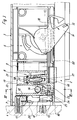
- the fitting comprises two support parts 6, two front panel holders 7 and two intermediate pieces 8, these aforementioned parts each forming a structural unit and each being arranged in the region of the two guide rails 2.
- the supporting parts 6 are each firmly connected to the guide rails 2, for example via locking lugs 60, as indicated in FIG. 3.
- the support parts 6 can also be connected to the guide rails 2 in any other type of fastening.
- the front panel holder 7 are each attached to the front panel 4 at a distance from the two guide rails 2.
- the type of fastening is freely selectable and of minor importance for the present invention.
- Each intermediate piece 8 is pivotally connected to the support part 6 assigned to it as well as to the associated front panel holder 7, specifically about vertical axes 9 and 10 which, as FIG. 2 clearly shows, form the corner points of a parallelogram.
- the intermediate pieces 8 are mounted on a pin 11 relative to the supporting parts 6.
- the front panel holder 7 have hinge pin-like bolts 12 which engage in correspondingly designed bearing recesses 13 of the respective intermediate piece 8.
- an adjusting screw 14 which is screwed into this intermediate piece within an intermediate piece - optionally on the left or on the right side of the furniture pull-out part 1 and rests with its end faces on two side walls 15 of the supporting part 6.
- This set screw 14, which can be actuated by means of a corresponding tool by means of preferably slot-like openings 16 within the walls 15, the respective intermediate piece 8 can be displaced horizontally relative to the support part 6 fastened to the guide rail 2. Because of the parallelogram-like connection, the front panel 4 is shifted parallel to the left or right depending on the direction of rotation of the adjusting screw 14, so that the front panel can be adjusted properly in this respect.
- a height adjustment screw 17 is provided in both intermediate pieces 8 in this case.
- This height adjustment screw 17 is rotatably mounted within the respective intermediate piece 8, but axially but non-displaceably, and is screwed with its threaded region into a threaded insert 18, which is located within the stationary supporting part 6.
- actuating one or both of these height adjustment screws 17, the front panel is raised or lowered in the area in which the respective height adjustment screw 17 is operated.
- the height adjustment screws 17 are provided in the area of their head 19 with an annular groove 20 into which a bow spring 21 engages. This bow spring 21 is fixed within a transverse slot 22 of the intermediate piece 8 in the axial direction of the height adjustment screw 17 and thus also the height adjustment screw 17 itself.
- the height adjustment screw 17 acts as an adjusting spindle and raises or lowers the respective intermediate piece 8 when it is actuated, and although relative to the supporting part 6, which can be designated as stationary.
- each support part 6 resilient retaining tab 23 is formed, which is provided at its free end with a receiving fork 24.
- a locking pin 25 integrally formed on the respective intermediate piece 8 engages in this receiving fork 24.
- the retaining tabs 23 of the support parts 6 run radially towards the bolts 12 and the distance between the two retaining tabs 23 corresponds exactly to the spacing of the bolts 12 of the front panel holder 7 mounted on the front panel 4 predetermined distance from each other secured by the spring action of the retaining tabs 23, so that the hanging of the front panel 4 by means of the front panel holder 7 in the intermediate pieces 8 is facilitated.
- An adjustment of these intermediate pieces 4 via the adjusting screw 14, however, is possible at any time due to the resilient effect of the retaining tabs 23.
- each front panel holder 7 is secured against unintentional lifting after the insertion of its bolts 12 into the bearing recesses 13 of the intermediate pieces 3 provided for this purpose, which engages under the upper bearing in the exemplary embodiment shown and is supported on it. Deviating from this, it is of course also conceivable to implement a latching between each front panel holder 7 and the associated intermediate piece 8 at a different location.
- the latching can be deliberately released and then the front panel 4 can be removed comfortably.
- the support parts 6 of the fitting are advantageously also used to accommodate a self-closing device 30 for the furniture pull-out part 1.
- This self-retracting device 30 consists essentially of a spring-loaded lever 31 which is rotatably mounted in the respective support part 6 and which cooperates with an actuating pin 32 fixed on the guide rail 2 shortly before the furniture insert part 1 is finally inserted, ie the lever 31 becomes short by the actuating pin 32 actuated before the final retraction and due to the spring loading, the furniture pull-out part is now finally pulled into its closed position.
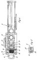
- FIGS. 9 to 11 show an exemplary embodiment of the invention, the basic structure of which corresponds to the exemplary embodiments described above.
- the fitting according to FIGS. 9 to 11 has been further developed so that the right-angled position between the guide rails 2 on the one hand and one mounted front panel 4, on the other hand, is also secured when an insert part, usually coupled to the guide rails 2, is removed in the form of a shell or a box.
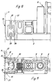
- each support part 6 has at least one front panel stabilizer in the form of a bracket 35 which extends in the direction of the front panel holder 7 and has a support surface 36 for the front panel 4 at its free end.
- the fitting for fixing the front panel 4 comprises two supporting parts 6, two front panel holders 7 and two intermediate pieces 8, these aforementioned parts each forming a structural unit and being arranged in the region of the two guide rails 2.
- a fitting consisting of the aforementioned components is connected to each guide rail 2.
- the support parts 6 are each firmly connected to the guide rails 2.
- the front panel holder 7 are each fixed to the front panel 4 at a distance from the two guide rails 2.
- the respective intermediate piece 8 is pivotally connected to the support part 6 assigned to it as well as to the front panel holder 7 assigned to it, specifically about vertical axes 9 and 10, which form the corner points of a parallelogram.
- the front panel 4 can be aligned and adjusted via the fittings using known and therefore not shown adjustment devices.
- the structure consisting of the guide rails 2 and the front panel 4 becomes inherently unstable, i.e. with one-sided tension or pressure on the front panel 4, this front panel 4 can be inclined within certain limits relative to the guide rails 2.
- the supporting parts 6 are each equipped with at least one front panel stabilizer in the form of a boom 35.
- These arms 35 which are either made in one piece with the support part 6 or are preferably detachably connected to this support part 6, extend in the direction of the front panel holder 7 to the inside of the front panel 4 and lie with their free end faces Ends, each of which forms a support surface 36 for the front panel 4, on this front panel 4.
- the boom 35 can be fork-shaped and enclose the intermediate piece 8 between it with its two legs.
- the cantilevers 35 can have an angled web 37 enlarging the supporting surface at their front ends.
- FIG. 10 shows very clearly that the arms 35 are provided with recesses 38 and notches 39, which bring about a relatively high spring elasticity of the arms 35.
Landscapes
- Drawers Of Furniture (AREA)
- Joining Of Building Structures In Genera (AREA)
- Assembled Shelves (AREA)
- Connection Of Plates (AREA)
- Vehicle Step Arrangements And Article Storage (AREA)
- Fittings On The Vehicle Exterior For Carrying Loads, And Devices For Holding Or Mounting Articles (AREA)
- Body Structure For Vehicles (AREA)
- Casings For Electric Apparatus (AREA)
- Finishing Walls (AREA)
Applications Claiming Priority (4)
| Application Number | Priority Date | Filing Date | Title |
|---|---|---|---|
| DE4433574 | 1994-09-21 | ||
| DE4433574A DE4433574A1 (de) | 1994-09-21 | 1994-09-21 | Beschlag zur einstellbaren Festlegung einer Frontblende |
| DE29504146U | 1995-03-10 | ||
| DE29504146U DE29504146U1 (de) | 1995-03-10 | 1995-03-10 | Beschlag zur einstellbaren Festlegung einer Frontblende |
Publications (3)
| Publication Number | Publication Date |
|---|---|
| EP0702915A2 true EP0702915A2 (fr) | 1996-03-27 |
| EP0702915A3 EP0702915A3 (fr) | 1998-07-22 |
| EP0702915B1 EP0702915B1 (fr) | 2002-11-13 |
Family
ID=25940296
Family Applications (1)
| Application Number | Title | Priority Date | Filing Date |
|---|---|---|---|
| EP95111675A Expired - Lifetime EP0702915B1 (fr) | 1994-09-21 | 1995-07-24 | Ferrure pour la fixation réglable d'un panneau frontal |
Country Status (6)
| Country | Link |
|---|---|
| EP (1) | EP0702915B1 (fr) |
| AT (1) | ATE227531T1 (fr) |
| DE (1) | DE59510456D1 (fr) |
| DK (1) | DK0702915T3 (fr) |
| ES (1) | ES2185675T3 (fr) |
| PT (1) | PT702915E (fr) |
Cited By (4)
| Publication number | Priority date | Publication date | Assignee | Title |
|---|---|---|---|---|
| EP0827703A1 (fr) * | 1996-09-09 | 1998-03-11 | Paul Hettich Gmbh & Co. | Ferrure pour la fixation réglable d'un panneau frontal |
| DE202008014470U1 (de) * | 2008-10-31 | 2010-03-18 | Paul Hettich Gmbh & Co. Kg | Frontverstellung für Schubkästen |
| WO2012159139A1 (fr) * | 2011-05-24 | 2012-11-29 | Julius Blum Gmbh | Dispositif de fixation servant à fixer un panneau de façade sur un tiroir |
| US11266240B2 (en) * | 2019-09-26 | 2022-03-08 | Liberty Hardware Mfg. Corp. | Drawer assembly |
Family Cites Families (1)
| Publication number | Priority date | Publication date | Assignee | Title |
|---|---|---|---|---|
| AT398265B (de) * | 1990-01-22 | 1994-11-25 | Blum Gmbh Julius | Befestigungsvorrichtung für die frontblende einer schublade |
-
1995
- 1995-07-24 DK DK95111675T patent/DK0702915T3/da active
- 1995-07-24 AT AT95111675T patent/ATE227531T1/de active
- 1995-07-24 ES ES95111675T patent/ES2185675T3/es not_active Expired - Lifetime
- 1995-07-24 EP EP95111675A patent/EP0702915B1/fr not_active Expired - Lifetime
- 1995-07-24 DE DE59510456T patent/DE59510456D1/de not_active Expired - Lifetime
- 1995-07-24 PT PT95111675T patent/PT702915E/pt unknown
Non-Patent Citations (1)
| Title |
|---|
| None |
Cited By (8)
| Publication number | Priority date | Publication date | Assignee | Title |
|---|---|---|---|---|
| EP0827703A1 (fr) * | 1996-09-09 | 1998-03-11 | Paul Hettich Gmbh & Co. | Ferrure pour la fixation réglable d'un panneau frontal |
| DE202008014470U1 (de) * | 2008-10-31 | 2010-03-18 | Paul Hettich Gmbh & Co. Kg | Frontverstellung für Schubkästen |
| WO2012159139A1 (fr) * | 2011-05-24 | 2012-11-29 | Julius Blum Gmbh | Dispositif de fixation servant à fixer un panneau de façade sur un tiroir |
| CN103561610A (zh) * | 2011-05-24 | 2014-02-05 | 尤利乌斯·布卢姆有限公司 | 用于将面板固定在抽屉上的固定装置 |
| US9033436B2 (en) | 2011-05-24 | 2015-05-19 | Julius Blum Gmbh | Fastening device for mounting a front cover on a drawer |
| CN103561610B (zh) * | 2011-05-24 | 2016-02-17 | 尤利乌斯·布卢姆有限公司 | 用于将面板固定在抽屉上的固定装置 |
| RU2585569C2 (ru) * | 2011-05-24 | 2016-05-27 | Юлиус Блум Гмбх | Крепежное устройство для закрепления передней панели на выдвижном ящике |
| US11266240B2 (en) * | 2019-09-26 | 2022-03-08 | Liberty Hardware Mfg. Corp. | Drawer assembly |
Also Published As
| Publication number | Publication date |
|---|---|
| DE59510456D1 (de) | 2002-12-19 |
| ES2185675T3 (es) | 2003-05-01 |
| EP0702915B1 (fr) | 2002-11-13 |
| EP0702915A3 (fr) | 1998-07-22 |
| PT702915E (pt) | 2003-02-28 |
| DK0702915T3 (da) | 2003-03-03 |
| ATE227531T1 (de) | 2002-11-15 |
Similar Documents
| Publication | Publication Date | Title |
|---|---|---|
| EP1147725B1 (fr) | Guide de sortie pour tiroirs | |
| EP2164363B1 (fr) | Châssis de tiroir avec un dispositif de fixation pour un panneau avant | |
| AT505177B1 (de) | Schublade mit schubladenunterteilung | |
| EP3603449A1 (fr) | Guidage d'extraction pour un tiroir | |
| DE29906637U1 (de) | Computertisch | |
| EP0198056B1 (fr) | Support de siege pour chaises, surtout pour des chaises de travail | |
| EP3381325B1 (fr) | Guide d'extraction pour une pièce de meuble pouvant être tirée d'une structure de meuble de base | |
| EP3681347B1 (fr) | Support de panneau et tiroir | |
| EP0476313A1 (fr) | Combinaison de meubles de bureau | |
| AT520427B1 (de) | Befestigungsvorrichtung zum lösbaren Befestigen einer Frontblende an einer Schublade | |
| EP0065036B1 (fr) | Table à dessus réglable | |
| EP2531071B1 (fr) | Assemblage de glissière pour tiroir avec un dispositif d'inclinaison | |
| EP3742931B1 (fr) | Glissière de guidage pour un tiroir et procédé pour aligner un tiroir à une glissière de guidage | |
| DE3931867C1 (fr) | ||
| EP0702915B1 (fr) | Ferrure pour la fixation réglable d'un panneau frontal | |
| DE3141158A1 (de) | Fuehrungsvorrichtung fuer einen ein- und ausfahrbaren einsatz im korpus einer dentaleinrichtung | |
| CH682294A5 (fr) | ||
| EP0806163A1 (fr) | Dispositif pour supporter un élément encastré coulissant et pivotant dans une unité d'armoire | |
| EP4705601A1 (fr) | Dispositif de guidage, chariot de guidage et unité fonctionnelle | |
| EP1342864A1 (fr) | Dispositif d'inclinaison pour un store à bras articulés | |
| AT399086B (de) | Verstellvorrichtung für schubladenblenden, insbesondere für küchenmöbelauszüge | |
| DE20007034U1 (de) | Ausziehsperre für mehrere übereinander angeordnete Schubladen | |
| EP2353444B1 (fr) | Tiroir d'armoire | |
| DE2821101C3 (de) | Auszugführung für in einem Gestell gehaltene Schubladen o.dgl | |
| DE4433574A1 (de) | Beschlag zur einstellbaren Festlegung einer Frontblende |
Legal Events
| Date | Code | Title | Description |
|---|---|---|---|
| PUAI | Public reference made under article 153(3) epc to a published international application that has entered the european phase |
Free format text: ORIGINAL CODE: 0009012 |
|
| AK | Designated contracting states |
Kind code of ref document: A2 Designated state(s): AT BE CH DE DK ES FR GB GR IE IT LI LU MC NL PT SE |
|
| PUAL | Search report despatched |
Free format text: ORIGINAL CODE: 0009013 |
|
| AK | Designated contracting states |
Kind code of ref document: A3 Designated state(s): AT BE CH DE DK ES FR GB GR IE IT LI LU MC NL PT SE |
|
| 17P | Request for examination filed |
Effective date: 19981223 |
|
| GRAG | Despatch of communication of intention to grant |
Free format text: ORIGINAL CODE: EPIDOS AGRA |
|
| GRAG | Despatch of communication of intention to grant |
Free format text: ORIGINAL CODE: EPIDOS AGRA |
|
| GRAH | Despatch of communication of intention to grant a patent |
Free format text: ORIGINAL CODE: EPIDOS IGRA |
|
| 17Q | First examination report despatched |
Effective date: 20020619 |
|
| GRAH | Despatch of communication of intention to grant a patent |
Free format text: ORIGINAL CODE: EPIDOS IGRA |
|
| GRAA | (expected) grant |
Free format text: ORIGINAL CODE: 0009210 |
|
| AK | Designated contracting states |
Kind code of ref document: B1 Designated state(s): AT BE CH DE DK ES FR GB GR IE IT LI LU MC NL PT SE |
|
| PG25 | Lapsed in a contracting state [announced via postgrant information from national office to epo] |
Ref country code: NL Free format text: LAPSE BECAUSE OF FAILURE TO SUBMIT A TRANSLATION OF THE DESCRIPTION OR TO PAY THE FEE WITHIN THE PRESCRIBED TIME-LIMIT Effective date: 20021113 Ref country code: GR Free format text: LAPSE BECAUSE OF FAILURE TO SUBMIT A TRANSLATION OF THE DESCRIPTION OR TO PAY THE FEE WITHIN THE PRESCRIBED TIME-LIMIT Effective date: 20021113 |
|
| REF | Corresponds to: |
Ref document number: 227531 Country of ref document: AT Date of ref document: 20021115 Kind code of ref document: T |
|
| REG | Reference to a national code |
Ref country code: GB Ref legal event code: FG4D Free format text: NOT ENGLISH |
|
| REG | Reference to a national code |
Ref country code: CH Ref legal event code: EP |
|
| REG | Reference to a national code |
Ref country code: CH Ref legal event code: NV Representative=s name: ISLER & PEDRAZZINI AG |
|
| REG | Reference to a national code |
Ref country code: IE Ref legal event code: FG4D Free format text: GERMAN |
|
| REF | Corresponds to: |
Ref document number: 59510456 Country of ref document: DE Date of ref document: 20021219 |
|
| REG | Reference to a national code |
Ref country code: PT Ref legal event code: SC4A Free format text: AVAILABILITY OF NATIONAL TRANSLATION Effective date: 20030110 |
|
| REG | Reference to a national code |
Ref country code: DK Ref legal event code: T3 |
|
| NLV1 | Nl: lapsed or annulled due to failure to fulfill the requirements of art. 29p and 29m of the patents act | ||
| GBT | Gb: translation of ep patent filed (gb section 77(6)(a)/1977) |
Effective date: 20030315 |
|
| REG | Reference to a national code |
Ref country code: ES Ref legal event code: FG2A Ref document number: 2185675 Country of ref document: ES Kind code of ref document: T3 |
|
| ET | Fr: translation filed | ||
| PG25 | Lapsed in a contracting state [announced via postgrant information from national office to epo] |
Ref country code: LU Free format text: LAPSE BECAUSE OF NON-PAYMENT OF DUE FEES Effective date: 20030724 Ref country code: IE Free format text: LAPSE BECAUSE OF NON-PAYMENT OF DUE FEES Effective date: 20030724 Ref country code: GB Free format text: LAPSE BECAUSE OF NON-PAYMENT OF DUE FEES Effective date: 20030724 |
|
| PG25 | Lapsed in a contracting state [announced via postgrant information from national office to epo] |
Ref country code: SE Free format text: LAPSE BECAUSE OF NON-PAYMENT OF DUE FEES Effective date: 20030725 |
|
| PG25 | Lapsed in a contracting state [announced via postgrant information from national office to epo] |
Ref country code: MC Free format text: LAPSE BECAUSE OF NON-PAYMENT OF DUE FEES Effective date: 20030731 Ref country code: LI Free format text: LAPSE BECAUSE OF NON-PAYMENT OF DUE FEES Effective date: 20030731 Ref country code: DK Free format text: LAPSE BECAUSE OF NON-PAYMENT OF DUE FEES Effective date: 20030731 Ref country code: CH Free format text: LAPSE BECAUSE OF NON-PAYMENT OF DUE FEES Effective date: 20030731 Ref country code: BE Free format text: LAPSE BECAUSE OF NON-PAYMENT OF DUE FEES Effective date: 20030731 |
|
| PLBE | No opposition filed within time limit |
Free format text: ORIGINAL CODE: 0009261 |
|
| STAA | Information on the status of an ep patent application or granted ep patent |
Free format text: STATUS: NO OPPOSITION FILED WITHIN TIME LIMIT |
|
| 26N | No opposition filed |
Effective date: 20030814 |
|
| BERE | Be: lapsed |
Owner name: PAUL *HETTICH G.M.B.H. & CO. Effective date: 20030731 |
|
| PG25 | Lapsed in a contracting state [announced via postgrant information from national office to epo] |
Ref country code: PT Free format text: LAPSE BECAUSE OF NON-PAYMENT OF DUE FEES Effective date: 20040131 |
|
| EUG | Se: european patent has lapsed | ||
| REG | Reference to a national code |
Ref country code: CH Ref legal event code: PL Ref country code: DK Ref legal event code: EBP |
|
| GBPC | Gb: european patent ceased through non-payment of renewal fee |
Effective date: 20030724 |
|
| REG | Reference to a national code |
Ref country code: PT Ref legal event code: MM4A Free format text: LAPSE DUE TO NON-PAYMENT OF FEES Effective date: 20040131 |
|
| REG | Reference to a national code |
Ref country code: IE Ref legal event code: MM4A |
|
| PGFP | Annual fee paid to national office [announced via postgrant information from national office to epo] |
Ref country code: DE Payment date: 20120921 Year of fee payment: 18 Ref country code: ES Payment date: 20120723 Year of fee payment: 18 Ref country code: FR Payment date: 20120803 Year of fee payment: 18 Ref country code: IT Payment date: 20120725 Year of fee payment: 18 |
|
| PGFP | Annual fee paid to national office [announced via postgrant information from national office to epo] |
Ref country code: AT Payment date: 20120720 Year of fee payment: 18 |
|
| REG | Reference to a national code |
Ref country code: AT Ref legal event code: MM01 Ref document number: 227531 Country of ref document: AT Kind code of ref document: T Effective date: 20130724 |
|
| REG | Reference to a national code |
Ref country code: DE Ref legal event code: R119 Ref document number: 59510456 Country of ref document: DE Effective date: 20140201 |
|
| REG | Reference to a national code |
Ref country code: FR Ref legal event code: ST Effective date: 20140331 |
|
| PG25 | Lapsed in a contracting state [announced via postgrant information from national office to epo] |
Ref country code: DE Free format text: LAPSE BECAUSE OF NON-PAYMENT OF DUE FEES Effective date: 20140201 |
|
| PG25 | Lapsed in a contracting state [announced via postgrant information from national office to epo] |
Ref country code: IT Free format text: LAPSE BECAUSE OF NON-PAYMENT OF DUE FEES Effective date: 20130724 Ref country code: AT Free format text: LAPSE BECAUSE OF NON-PAYMENT OF DUE FEES Effective date: 20130724 Ref country code: FR Free format text: LAPSE BECAUSE OF NON-PAYMENT OF DUE FEES Effective date: 20130731 |
|
| REG | Reference to a national code |
Ref country code: ES Ref legal event code: FD2A Effective date: 20140908 |
|
| PG25 | Lapsed in a contracting state [announced via postgrant information from national office to epo] |
Ref country code: ES Free format text: LAPSE BECAUSE OF NON-PAYMENT OF DUE FEES Effective date: 20130725 |