EP0703002A1 - Regenerierung eines Fluorwasserstoff-Alkylierungskatalysator - Google Patents
Regenerierung eines Fluorwasserstoff-Alkylierungskatalysator Download PDFInfo
- Publication number
- EP0703002A1 EP0703002A1 EP95113560A EP95113560A EP0703002A1 EP 0703002 A1 EP0703002 A1 EP 0703002A1 EP 95113560 A EP95113560 A EP 95113560A EP 95113560 A EP95113560 A EP 95113560A EP 0703002 A1 EP0703002 A1 EP 0703002A1
- Authority
- EP
- European Patent Office
- Prior art keywords
- zone
- aso
- concentration
- catalyst
- phase
- Prior art date
- Legal status (The legal status is an assumption and is not a legal conclusion. Google has not performed a legal analysis and makes no representation as to the accuracy of the status listed.)
- Granted
Links
Images
Classifications
-
- B—PERFORMING OPERATIONS; TRANSPORTING
- B01—PHYSICAL OR CHEMICAL PROCESSES OR APPARATUS IN GENERAL
- B01J—CHEMICAL OR PHYSICAL PROCESSES, e.g. CATALYSIS OR COLLOID CHEMISTRY; THEIR RELEVANT APPARATUS
- B01J27/00—Catalysts comprising the elements or compounds of halogens, sulfur, selenium, tellurium, phosphorus or nitrogen; Catalysts comprising carbon compounds
- B01J27/28—Regeneration or reactivation
- B01J27/32—Regeneration or reactivation of catalysts comprising compounds of halogens
-
- C—CHEMISTRY; METALLURGY
- C07—ORGANIC CHEMISTRY
- C07C—ACYCLIC OR CARBOCYCLIC COMPOUNDS
- C07C2/00—Preparation of hydrocarbons from hydrocarbons containing a smaller number of carbon atoms
- C07C2/54—Preparation of hydrocarbons from hydrocarbons containing a smaller number of carbon atoms by addition of unsaturated hydrocarbons to saturated hydrocarbons or to hydrocarbons containing a six-membered aromatic ring with no unsaturation outside the aromatic ring
- C07C2/56—Addition to acyclic hydrocarbons
- C07C2/58—Catalytic processes
- C07C2/62—Catalytic processes with acids
-
- C—CHEMISTRY; METALLURGY
- C07—ORGANIC CHEMISTRY
- C07C—ACYCLIC OR CARBOCYCLIC COMPOUNDS
- C07C2527/00—Catalysts comprising the elements or compounds of halogens, sulfur, selenium, tellurium, phosphorus or nitrogen; Catalysts comprising carbon compounds
- C07C2527/06—Halogens; Compounds thereof
- C07C2527/08—Halides
- C07C2527/12—Fluorides
- C07C2527/1206—Hydrogen fluoride
-
- Y—GENERAL TAGGING OF NEW TECHNOLOGICAL DEVELOPMENTS; GENERAL TAGGING OF CROSS-SECTIONAL TECHNOLOGIES SPANNING OVER SEVERAL SECTIONS OF THE IPC; TECHNICAL SUBJECTS COVERED BY FORMER USPC CROSS-REFERENCE ART COLLECTIONS [XRACs] AND DIGESTS
- Y02—TECHNOLOGIES OR APPLICATIONS FOR MITIGATION OR ADAPTATION AGAINST CLIMATE CHANGE
- Y02P—CLIMATE CHANGE MITIGATION TECHNOLOGIES IN THE PRODUCTION OR PROCESSING OF GOODS
- Y02P20/00—Technologies relating to chemical industry
- Y02P20/50—Improvements relating to the production of bulk chemicals
- Y02P20/584—Recycling of catalysts
Definitions
- This invention relates to the regeneration of a hydrogen fluoride catalyst used in an olefin and isoparaffin alkylation process.
- ASO acid soluble oil
- Another object of this invention is to provide an HF alkylation catalyst regeneration process which removes ASO from such HF alkylation catalyst with a minimum of loss of HF which is removed along with the ASO product.
- the inventive process provides for the regeneration of an HF catalyst used in the alkylation of olefins with isoparaffins and containing therein HF and ASO.
- Separation means for separating ASO from the HF catalyst is utilized.
- the separation means comprises a separation column, which defines a separation zone with the separation zone having a top zone, an intermediate zone, and a bottom zone, wherein contained within the bottom zone is a series of vertically spaced, fixed valve fractionation trays, wherein each of the fixed valve fractionation trays include a plate defining a plurality of apertures and wherein fixedly spaced above each of the apertures is a valve having a shape substantially the same as the apertures for directing the flow of gas passing upwardly through the apertures of the plate into the direction substantially parallel to the plate.
- HF catalyst is introduced into the intermediate zone of the separation column while a reflux of liquid isoparaffin is introduced into the top zone of the separation column and a vaporous isoparaffin stripping fluid is introduced into the bottom zone of the separation column but below the series of vertically spaced, fixed valve fractionator trays.
- Removed from the separation column is an overhead stream of HF and a bottom stream of ASO.
- the separation means comprises a separation column, which defines a separation zone, and a bottom zone, wherein contained within the bottom zone is a series of vertically spaced fractionation trays.
- HF catalyst is introduced into the intermediate zone of the separation column while a reflux of liquid isoparaffin is introduced into the top zone of the separation column and a vaporous isoparaffin stripping fluid is introduced into the bottom zone of the separation column but below the series of vertically spaced fractionator trays.
- Removed from the separation column is an overhead stream of HF.
- At least two liquid phases including an upper phase having an HF concentration and a lower phase having an HF concentration greater than the HF concentration of the upper phase.
- the upper phase is removed from the bottom zone and the lower phase is introduced into the intermediate zone of the separation means.
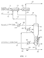
- alkylation reactor 10 which defines an alkylation reaction zone.
- An olefin feed stream is introduced into alkylation reactor 10 through conduit 12 and an isoparaffin feed stream is introduced into alkylation reactor 10 through conduit 14.
- the olefin feed generally comprises one or more olefins having from 2 to 5 carbon atoms, while the isoparaffin stream generally comprises isobutane and/or isopentane.
- the olefin feed comprises a mixture of propylene and butylenes, while the isoparaffin feed comprises primarily isobutane.
- a catalyst comprising hydrogen fluoride is introduced into alkylation reactor 10 through conduit 16 and through recycle conduits 18 and 19.
- the HF is in the liquid phase and has a purity of at least about 90%.
- Fresh makeup catalyst can be introduced as required through conduit 16.
- the effluent from alkylation reactor 10 is passed to a settler 20 in which a phase separation is made between the acid phase and hydrocarbon phase.
- the hydrocarbon phase is removed from settler 20 through conduit 22 and passes to downstream processing.
- the acid phase is removed from settler 20 through conduit 24. At least a portion of the acid phase stream is recycled directly to alkylation reactor 10 through recycle conduit 19. The remainder of the acid phase stream is passed through conduit 28, having interposed therein heater 30 defining a heat transfer zone and providing means for transferring heat to the acid phase stream, to separator column 32.
- Separator column 32 defines a separation zone comprising a top zone, an intermediate zone, and a bottom zone and provides separation means for separating ASO from the HF of the acid phase.
- a purified HF stream is removed as an overhead stream from separator column 32 through conduit 18 and is recycled to alkylation reactor 10.
- An ASO stream can be removed as a bottoms stream from separator column 32 through conduits 34 and 36 or, alternatively, through conduit 37.
- a liquid hydrocarbon reflux is introduced into the top zone of separator column 32 through conduit 38 having interposed therein condenser 40 defining a heat transfer zone and providing means for transferring heat from the liquid hydrocarbon reflux.
- the reflux is introduced onto distribution tray 42 located within the top zone of separator column 32.
- the bottom zone of separator column 32 is provided with a plurality of vapor-liquid contacting means, such as fixed valve fractionator trays 50. Stripping isobutane is directed to the bottom zone of separator column 32 by conduit 44.
- vaporizer 48 Interposed in conduit 44 is vaporizer 48 which defines a heat transfer zone and provides means for heating and/or vaporizing the stripping isobutane introduced into separator column 32.
- a bottoms stream comprising ASO is removed from separator column 32 through conduit 34 and passes downstream by way of conduit 36.
- at least a portion of the bottoms stream can be recycled or returned to separator column 32 by way of conduit 52.
- pump 54 Interposed in conduit 52 is pump 54 for providing work input required to recycle the at least a portion of the bottoms stream to separator column 32.
- the at least a portion of the bottoms stream is introduced into the intermediate zone of separator column 32 at a location below the introduction entry point of the acid phase but above the bottom zone of separator column 32 wherein contained is a series of vertically spaced, fixed valve fractionator trays 50.
- a further embodiment of the invention includes, optionally, drawing the bottoms stream from separator column 32 through conduit 37.
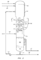
- FIG. 2 provides an enlarged detail of separator column 32, which includes the bottom zone, containing the series of vertically spaced, fixed valve fractionator trays 50.
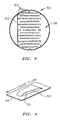
- Each of the vertically spaced, fixed valve fractionator trays 50 include a plate or a deck 56 having a thickness and defining therein a pattern or plurality of apertures 60 (shown in FIG. 3) for permitting the upwardly flow of gas therethrough.
- Each individual aperture 60 defined by each plate 56 represents a cross-sectional area in the range of from about 0.005 square feet to about 0.40 square feet, preferably from about 0.01 square feet to about 0.30 square feet and, most preferably, from 0.015 square feet to 0.25 square feet.
- each fixed valve fractionator tray 50 Provided with each fixed valve fractionator tray 50 is a downcomer 62.
- Each downcomer 62 can comprise vertical plates secured along opposite edges thereof to the interior surface of separator column 32 so as to extend entirely across the interior of separator column 32.
- the vertical plate of downcomer 62 extends upwardly above the plane of plate 56 so as to provide an edge 64, which defines an overflow weir, having a height of from about 0.5 inches to about 4 inches, for retaining a level of liquid upon each plate 56.
- the vertical plate of downcomer 62 also extends downwardly to close proximity of the fixed valve fractionator tray 50 positioned below.
- the downcomers 62 are located on opposite sides of the interior of separator column 32 so as to guide liquids from a fixed valve fractionator tray 50 above to a fixed valve fractionator tray 50 below until the liquid passes along the last of such trays and is directed by its downcomer 62 to the bottom of separator column 32.
- the arrangement of fixed valve fractionator trays 50 and downcomers 62 provide for the stair step type flow of liquids down the interior of separator column 32 with the liquid passing horizontally along each plate 56 and being directed to the tray below each downcomer 62.
- the liquid is held on top of each tray by gases that flow upwardly through separator column 32 and passing through apertures 60.
- the gas flow through apertures 60 should be sufficient to prevent a substantial portion of the liquid contained on top of each plate 56 to fall through such apertures and sufficient to maintain a level of liquid on top of each tray 50.
- the liquid level formed or provided in the bottom zone of separator column 32 primarily contains ASO, but it also contains a concentration of HF. It has been discovered that at least two liquid phases will form in the bottom zone of separator column 32.
- the top phase, or upper phase 66 will have a concentration of HF that is less than the concentration of HF in the bottom phase, or lower phase 68.
- upper phase 66 will have an HF concentration of less than about 20 weight percent, preferably less than about 10 weight percent and, most preferably, less than 5 weight percent.
- the HF concentration is greater than the HF concentration of the upper phase and can be as high as about 50 weight percent.
- the bottoms stream drawn from separator column 32 it is important for the bottoms stream drawn from separator column 32 to be taken from upper phase 66 as opposed to lower phase 68.
- upper phase 66 as the bottoms stream, as opposed to lower phase 68, HF loss is reduced due to the lower HF concentration in upper phase 66.
- each plate 56 shall define a plurality of apertures 60, but associated with each of such aperture 60 is a fixed valve 64 fixedly spaced above each aperture 60.
- the fixed valve 70 has substantially the same shape as its associated aperture 60 and is provided to direct the flow of the gases which are passing upwardly through apertures 60 in the horizontal direction parallel to plate 56. This configuration provides for the intimate contacting of the upwardly flowing gases with the liquid flowing across each plate 56.
- the distance of the fixed space above each aperture 60 is in the range of from about 0.1 inches to about 0.5 inches, preferably from about 0.15 inches to about 0.45 inches and, most preferably, from 0.2 inches to 0.4 inches.
- the ASO-containing HF catalyst is charged to the intermediate zone of separator column 32 at a temperature in the range of from about 200°F to about 300°F, preferably, however, in the range of from 250°F to 295°F.
- the temperature of the overhead stream of purified HF comprising HF can be in the range of from about 200°F to about 300°F and, preferably between 250°F and 295°F.
- the isoparaffin reflux stream its temperature can be in the range of from about 40°F to about 140°F, preferably, 60°F to 120°F.
- the preferred isoparaffin for use as the isoparaffin reflux stream is isobutane.
- the stripping isoparaffin stream is introduced into the bottom zone of separator column 32 at an entry point below the series of vertically spaced, fixed valve fractionator trays contained within the bottom zone of separator column 32, and is in the form of a vapor or a gas.
- This vaporous isoparaffin rises upwardly through apertures 60 of each fixed valve fractionator tray 50 and provides for the separation of ASO and HF from the ASO-containing HF catalyst.
- the preferred stripping isoparaffin is isobutane, and it can have a temperature exceeding about 275°F and, preferably, can be in the range of from 300°F to 400°F.
- the pressure at which column 32 is operated can generally be in the range of from 100 psia to 200 psia, preferably, from 125 psia to 175 psia.
- the ASO-containing HF catalyst will generally have a concentration of ASO exceeding about 1.0 weight percent ASO based on the total weight of the ASO-containing HF catalyst.
- the ASO concentration can be in the range of from about 1.25 weight percent to about 10 weight percent, and, more specifically, it can be in the range of from 1.5 weight percent to 5 weight percent.
- the overhead stream of purified HF comprising HF shall have a concentration of ASO that is lower than that of the ASO-containing HF catalyst. Therefore, the ASO concentration will generally be less than 1.0 weight percent.
- the bottoms stream of ASO will comprise ASO at a concentration of at least about 50 weight percent based on the total weight of the bottoms streams.
- the ASO concentration can be at least about 60 weight percent and, more preferably, it can be at least 70 weight percent.
- the HF concentration can be less than about 50 weight percent of the bottoms stream, preferably less than about 40 weight percent and, most preferably less than 30 weight percent.
- the liquid level established in the bottom zone of separator column 32 forms at least two separate liquid phases, including an upper phase and a lower phase.
- the upper phase has a concentration of HF that is smaller than the concentration of HF in the lower phase.
- the lower phase will have a concentration of HF that is greater than the concentration of HF in the upper phase.
- the concentration of HF in the upper phase is less than about 20 weight percent, preferably, less than about 10 weight percent and, most preferably, less than 5 weight percent.
- the lower phase has an HF concentration as high as about 50 weight percent.
- Table I provides actual HF losses for each of six time periods immediately prior to the modification of the separation column and for each of seven time periods subsequent to the modification of the separation column.
- the data show that the average HF lost in the ASO bottoms product for the conventional process was 34,676 pounds per time period and was significantly higher than the average HF loss of 18,633 pounds per time period after the installation and operation of the novel process.
- These figures amounted to an average acid consumption in the associated alkylation process of 0.12 pounds HF per barrel alkylate produced for the conventional process versus 0.06 pounds of HF per barrel alkylate produced for the novel process.
- This example provides selected values from a calculated material balance used for designing a revamp of an acid rerun column of a Phillips Petroleum Company HF Alkylation Process Unit.
- the stream numbers correspond to those of FIG's. 1 and 2.
- the HF concentration of stream 37 is 0.5 weight percent as compared with an HF concentration of 10 weight percent for stream 34.
- the material balance shows that by recycling the bottom phase, HF loss with the ASO product is significantly reduced and minimized.
- Table II Selected Stream Compositions Stream No.
Landscapes
- Chemical & Material Sciences (AREA)
- Organic Chemistry (AREA)
- Chemical Kinetics & Catalysis (AREA)
- Engineering & Computer Science (AREA)
- Materials Engineering (AREA)
- Catalysts (AREA)
- Organic Low-Molecular-Weight Compounds And Preparation Thereof (AREA)
- Production Of Liquid Hydrocarbon Mixture For Refining Petroleum (AREA)
- Low-Molecular Organic Synthesis Reactions Using Catalysts (AREA)
- Vaporization, Distillation, Condensation, Sublimation, And Cold Traps (AREA)
Applications Claiming Priority (2)
| Application Number | Priority Date | Filing Date | Title |
|---|---|---|---|
| US08/298,016 US5527980A (en) | 1994-02-24 | 1994-08-30 | Regeneration of hydrogen fluoride alkylation catalyst |
| US298016 | 1994-08-30 |
Publications (2)
| Publication Number | Publication Date |
|---|---|
| EP0703002A1 true EP0703002A1 (de) | 1996-03-27 |
| EP0703002B1 EP0703002B1 (de) | 1999-11-03 |
Family
ID=23148642
Family Applications (1)
| Application Number | Title | Priority Date | Filing Date |
|---|---|---|---|
| EP95113560A Expired - Lifetime EP0703002B1 (de) | 1994-08-30 | 1995-08-29 | Regenerierung eines Fluorwasserstoff-Alkylierungskatalysator |
Country Status (16)
| Country | Link |
|---|---|
| US (1) | US5527980A (de) |
| EP (1) | EP0703002B1 (de) |
| JP (1) | JPH0871432A (de) |
| KR (1) | KR960007004A (de) |
| AT (1) | ATE186231T1 (de) |
| AU (1) | AU673308B2 (de) |
| BR (1) | BR9503035A (de) |
| CA (1) | CA2152337C (de) |
| DE (1) | DE69513118T2 (de) |
| DK (1) | DK0703002T3 (de) |
| ES (1) | ES2137425T3 (de) |
| FI (1) | FI954054L (de) |
| GR (1) | GR3032305T3 (de) |
| HU (1) | HU219187B (de) |
| NO (1) | NO311332B1 (de) |
| TW (1) | TW287121B (de) |
Families Citing this family (3)
| Publication number | Priority date | Publication date | Assignee | Title |
|---|---|---|---|---|
| US6228650B1 (en) | 1997-12-17 | 2001-05-08 | Phillips Petroleum Company | Acid catalyst regeneration control |
| US7481871B2 (en) * | 2004-12-10 | 2009-01-27 | Exxonmobil Chemical Patents Inc. | Vapor/liquid separation apparatus |
| CN101743045A (zh) * | 2007-05-15 | 2010-06-16 | 三菱丽阳株式会社 | 蒸发器、蒸发方法以及甲基丙烯醛或(甲基)丙烯酸的制备方法 |
Citations (4)
| Publication number | Priority date | Publication date | Assignee | Title |
|---|---|---|---|---|
| FR2123414A1 (de) * | 1971-01-25 | 1972-09-08 | Phillips Petroleum Co | |
| US4014953A (en) * | 1975-02-05 | 1977-03-29 | Phillips Petroleum Company | Method for purifying HF catalyst in an isoparaffin-olefin alkylation |
| US4316998A (en) * | 1980-07-29 | 1982-02-23 | Phillips Petroleum Company | Treatment of sulfur-containing HF-alkylation feed, hydrocarbon product, propane and acid-soluble oils derived from the alkylation |
| EP0184375A1 (de) * | 1984-11-28 | 1986-06-11 | Mobil Oil Corporation | Lösungsmittelextraktion und Reinigung eines säurelöslichen Öls aus einer Alkylierungsanlage |
Family Cites Families (6)
| Publication number | Priority date | Publication date | Assignee | Title |
|---|---|---|---|---|
| US2551881A (en) * | 1947-09-05 | 1951-05-08 | Phillips Petroleum Co | Method of recovering hydrogen fluoride |
| US2914590A (en) * | 1958-02-21 | 1959-11-24 | Phillips Petroleum Co | Hydrofluoric acid recovery from alkylation acid waste stream |
| US3793394A (en) * | 1972-05-08 | 1974-02-19 | Phillips Petroleum Co | Purification of hf catalyst in alkylation process |
| US3975164A (en) * | 1975-02-05 | 1976-08-17 | Phillips Petroleum Company | Apparatus for purifying HF catalyst in an alkylation process |
| US4199409A (en) * | 1977-02-22 | 1980-04-22 | Phillips Petroleum Company | Recovery of HF from an alkylation unit acid stream containing acid soluble oil |
| US4454369A (en) * | 1982-05-07 | 1984-06-12 | Phillips Petroleum Company | HF Alkylation process |
-
1994
- 1994-08-30 US US08/298,016 patent/US5527980A/en not_active Expired - Lifetime
-
1995
- 1995-06-21 CA CA002152337A patent/CA2152337C/en not_active Expired - Fee Related
- 1995-06-23 TW TW084106473A patent/TW287121B/zh active
- 1995-06-23 AU AU23217/95A patent/AU673308B2/en not_active Ceased
- 1995-06-29 KR KR1019950019333A patent/KR960007004A/ko not_active Ceased
- 1995-06-30 JP JP7166510A patent/JPH0871432A/ja active Pending
- 1995-06-30 BR BR9503035A patent/BR9503035A/pt not_active IP Right Cessation
- 1995-08-29 ES ES95113560T patent/ES2137425T3/es not_active Expired - Lifetime
- 1995-08-29 HU HU9502533A patent/HU219187B/hu not_active IP Right Cessation
- 1995-08-29 DE DE69513118T patent/DE69513118T2/de not_active Expired - Fee Related
- 1995-08-29 EP EP95113560A patent/EP0703002B1/de not_active Expired - Lifetime
- 1995-08-29 AT AT95113560T patent/ATE186231T1/de not_active IP Right Cessation
- 1995-08-29 NO NO19953379A patent/NO311332B1/no not_active IP Right Cessation
- 1995-08-29 FI FI954054A patent/FI954054L/fi unknown
- 1995-08-29 DK DK95113560T patent/DK0703002T3/da active
-
2000
- 2000-01-04 GR GR20000400005T patent/GR3032305T3/el not_active IP Right Cessation
Patent Citations (4)
| Publication number | Priority date | Publication date | Assignee | Title |
|---|---|---|---|---|
| FR2123414A1 (de) * | 1971-01-25 | 1972-09-08 | Phillips Petroleum Co | |
| US4014953A (en) * | 1975-02-05 | 1977-03-29 | Phillips Petroleum Company | Method for purifying HF catalyst in an isoparaffin-olefin alkylation |
| US4316998A (en) * | 1980-07-29 | 1982-02-23 | Phillips Petroleum Company | Treatment of sulfur-containing HF-alkylation feed, hydrocarbon product, propane and acid-soluble oils derived from the alkylation |
| EP0184375A1 (de) * | 1984-11-28 | 1986-06-11 | Mobil Oil Corporation | Lösungsmittelextraktion und Reinigung eines säurelöslichen Öls aus einer Alkylierungsanlage |
Also Published As
| Publication number | Publication date |
|---|---|
| FI954054A7 (fi) | 1996-03-02 |
| ES2137425T3 (es) | 1999-12-16 |
| EP0703002B1 (de) | 1999-11-03 |
| GR3032305T3 (en) | 2000-04-27 |
| HU9502533D0 (en) | 1995-10-30 |
| AU2321795A (en) | 1996-03-14 |
| TW287121B (de) | 1996-10-01 |
| HUT75950A (en) | 1997-05-28 |
| NO953379D0 (no) | 1995-08-29 |
| FI954054A0 (fi) | 1995-08-29 |
| CA2152337A1 (en) | 1996-03-01 |
| ATE186231T1 (de) | 1999-11-15 |
| JPH0871432A (ja) | 1996-03-19 |
| DE69513118D1 (de) | 1999-12-09 |
| KR960007004A (ko) | 1996-03-22 |
| BR9503035A (pt) | 1996-10-01 |
| FI954054L (fi) | 1996-03-02 |
| DK0703002T3 (da) | 2000-01-03 |
| NO311332B1 (no) | 2001-11-19 |
| NO953379L (no) | 1996-03-01 |
| HU219187B (hu) | 2001-02-28 |
| US5527980A (en) | 1996-06-18 |
| CA2152337C (en) | 1999-03-23 |
| DE69513118T2 (de) | 2000-03-02 |
| AU673308B2 (en) | 1996-10-31 |
Similar Documents
| Publication | Publication Date | Title |
|---|---|---|
| US4555311A (en) | Integrated fractionation in the recovery of alkylaromatic hydrocarbons | |
| BR9915373B1 (pt) | processo para a purificação dos produtos de reação de uma reação de adição direta. | |
| EP0669301B1 (de) | Regenerierung eines Fluorwasserstoff-Alkylierungskatalysator | |
| US3766021A (en) | Process and apparatus for fractionator reboiling with minimized fouling by centifuging and decanting | |
| US4014953A (en) | Method for purifying HF catalyst in an isoparaffin-olefin alkylation | |
| KR950008625B1 (ko) | 액체 분리 장치 및 액체 누출 감소 방법 | |
| US7339088B1 (en) | Alkylbenzene refining process and apparatus | |
| US3871969A (en) | Apparatus for purifying HF | |
| EP0703002B1 (de) | Regenerierung eines Fluorwasserstoff-Alkylierungskatalysator | |
| US4144281A (en) | HF Alkylation process utilizing compressed isoparaffin vapor in indirect heat exchanges | |
| US4513165A (en) | Alkylation process | |
| US4220806A (en) | Plural stages of hydrofluoric acid alkylation utilizing separated acid phase as catalyst in the subsequent stage | |
| US3793264A (en) | Purification of hf catalyst in alkylation process | |
| US3749753A (en) | Purification of hf catalyst in alkylation process | |
| US2820073A (en) | Alkylation of hydrocarbons | |
| GB2619881A (en) | Diving wall column in alkylation process for reactor recycle and product separation | |
| EP0154317B1 (de) | HF-Alkylierung mit Produktrückführung unter Verwendung von zwei Reaktoren | |
| US4311866A (en) | Separation of products of HF alkylation | |
| US3594444A (en) | Process for separating hydrocarbons and hydrogen fluoride catalyst from the effluent of an isoparaffin-olefin alkylation reaction zone | |
| US2984693A (en) | Defluorination of reaction products | |
| US3793394A (en) | Purification of hf catalyst in alkylation process | |
| US3879487A (en) | Hydrogen fluoride alkylation utilizing a heat exchanger in the settling zone | |
| US4373110A (en) | HF Alkylation process and apparatus | |
| US4180526A (en) | Alkylation process utilizing side draw vapor as heat source in isostripper | |
| US2408933A (en) | Hydrogen fluoride alkylation process |
Legal Events
| Date | Code | Title | Description |
|---|---|---|---|
| PUAI | Public reference made under article 153(3) epc to a published international application that has entered the european phase |
Free format text: ORIGINAL CODE: 0009012 |
|
| AK | Designated contracting states |
Kind code of ref document: A1 Designated state(s): AT BE DE DK ES FR GB GR IE IT NL PT SE |
|
| 17P | Request for examination filed |
Effective date: 19960730 |
|
| 17Q | First examination report despatched |
Effective date: 19980701 |
|
| GRAG | Despatch of communication of intention to grant |
Free format text: ORIGINAL CODE: EPIDOS AGRA |
|
| GRAG | Despatch of communication of intention to grant |
Free format text: ORIGINAL CODE: EPIDOS AGRA |
|
| GRAH | Despatch of communication of intention to grant a patent |
Free format text: ORIGINAL CODE: EPIDOS IGRA |
|
| GRAH | Despatch of communication of intention to grant a patent |
Free format text: ORIGINAL CODE: EPIDOS IGRA |
|
| GRAA | (expected) grant |
Free format text: ORIGINAL CODE: 0009210 |
|
| AK | Designated contracting states |
Kind code of ref document: B1 Designated state(s): AT BE DE DK ES FR GB GR IE IT NL PT SE |
|
| REF | Corresponds to: |
Ref document number: 186231 Country of ref document: AT Date of ref document: 19991115 Kind code of ref document: T |
|
| ITF | It: translation for a ep patent filed | ||
| REF | Corresponds to: |
Ref document number: 69513118 Country of ref document: DE Date of ref document: 19991209 |
|
| REG | Reference to a national code |
Ref country code: ES Ref legal event code: FG2A Ref document number: 2137425 Country of ref document: ES Kind code of ref document: T3 |
|
| REG | Reference to a national code |
Ref country code: DK Ref legal event code: T3 |
|
| REG | Reference to a national code |
Ref country code: IE Ref legal event code: FG4D |
|
| REG | Reference to a national code |
Ref country code: PT Ref legal event code: SC4A Free format text: AVAILABILITY OF NATIONAL TRANSLATION Effective date: 19991117 |
|
| ET | Fr: translation filed | ||
| PGFP | Annual fee paid to national office [announced via postgrant information from national office to epo] |
Ref country code: IE Payment date: 20000728 Year of fee payment: 6 |
|
| PLBE | No opposition filed within time limit |
Free format text: ORIGINAL CODE: 0009261 |
|
| STAA | Information on the status of an ep patent application or granted ep patent |
Free format text: STATUS: NO OPPOSITION FILED WITHIN TIME LIMIT |
|
| PGFP | Annual fee paid to national office [announced via postgrant information from national office to epo] |
Ref country code: AT Payment date: 20000907 Year of fee payment: 6 |
|
| 26N | No opposition filed | ||
| PGFP | Annual fee paid to national office [announced via postgrant information from national office to epo] |
Ref country code: DK Payment date: 20010615 Year of fee payment: 7 |
|
| PGFP | Annual fee paid to national office [announced via postgrant information from national office to epo] |
Ref country code: NL Payment date: 20010618 Year of fee payment: 7 |
|
| PGFP | Annual fee paid to national office [announced via postgrant information from national office to epo] |
Ref country code: GB Payment date: 20010629 Year of fee payment: 7 |
|
| PGFP | Annual fee paid to national office [announced via postgrant information from national office to epo] |
Ref country code: PT Payment date: 20010704 Year of fee payment: 7 |
|
| PGFP | Annual fee paid to national office [announced via postgrant information from national office to epo] |
Ref country code: GR Payment date: 20010725 Year of fee payment: 7 |
|
| PGFP | Annual fee paid to national office [announced via postgrant information from national office to epo] |
Ref country code: FR Payment date: 20010802 Year of fee payment: 7 |
|
| PGFP | Annual fee paid to national office [announced via postgrant information from national office to epo] |
Ref country code: SE Payment date: 20010803 Year of fee payment: 7 |
|
| PGFP | Annual fee paid to national office [announced via postgrant information from national office to epo] |
Ref country code: ES Payment date: 20010814 Year of fee payment: 7 |
|
| PG25 | Lapsed in a contracting state [announced via postgrant information from national office to epo] |
Ref country code: IE Free format text: LAPSE BECAUSE OF NON-PAYMENT OF DUE FEES Effective date: 20010829 Ref country code: AT Free format text: LAPSE BECAUSE OF NON-PAYMENT OF DUE FEES Effective date: 20010829 |
|
| PGFP | Annual fee paid to national office [announced via postgrant information from national office to epo] |
Ref country code: DE Payment date: 20010831 Year of fee payment: 7 |
|
| PGFP | Annual fee paid to national office [announced via postgrant information from national office to epo] |
Ref country code: BE Payment date: 20010912 Year of fee payment: 7 |
|
| REG | Reference to a national code |
Ref country code: GB Ref legal event code: IF02 |
|
| REG | Reference to a national code |
Ref country code: IE Ref legal event code: MM4A |
|
| PG25 | Lapsed in a contracting state [announced via postgrant information from national office to epo] |
Ref country code: GB Free format text: LAPSE BECAUSE OF NON-PAYMENT OF DUE FEES Effective date: 20020829 |
|
| PG25 | Lapsed in a contracting state [announced via postgrant information from national office to epo] |
Ref country code: SE Free format text: LAPSE BECAUSE OF NON-PAYMENT OF DUE FEES Effective date: 20020830 Ref country code: ES Free format text: LAPSE BECAUSE OF NON-PAYMENT OF DUE FEES Effective date: 20020830 |
|
| PG25 | Lapsed in a contracting state [announced via postgrant information from national office to epo] |
Ref country code: BE Free format text: LAPSE BECAUSE OF NON-PAYMENT OF DUE FEES Effective date: 20020831 |
|
| PG25 | Lapsed in a contracting state [announced via postgrant information from national office to epo] |
Ref country code: DK Free format text: LAPSE BECAUSE OF NON-PAYMENT OF DUE FEES Effective date: 20020930 |
|
| BERE | Be: lapsed |
Owner name: *PHILLIPS PETROLEUM CY Effective date: 20020831 |
|
| PG25 | Lapsed in a contracting state [announced via postgrant information from national office to epo] |
Ref country code: PT Free format text: LAPSE BECAUSE OF NON-PAYMENT OF DUE FEES Effective date: 20030228 |
|
| PG25 | Lapsed in a contracting state [announced via postgrant information from national office to epo] |
Ref country code: NL Free format text: LAPSE BECAUSE OF NON-PAYMENT OF DUE FEES Effective date: 20030301 Ref country code: DE Free format text: LAPSE BECAUSE OF NON-PAYMENT OF DUE FEES Effective date: 20030301 |
|
| PG25 | Lapsed in a contracting state [announced via postgrant information from national office to epo] |
Ref country code: GR Free format text: LAPSE BECAUSE OF NON-PAYMENT OF DUE FEES Effective date: 20030305 |
|
| EUG | Se: european patent has lapsed | ||
| REG | Reference to a national code |
Ref country code: DK Ref legal event code: EBP |
|
| GBPC | Gb: european patent ceased through non-payment of renewal fee |
Effective date: 20020829 |
|
| PG25 | Lapsed in a contracting state [announced via postgrant information from national office to epo] |
Ref country code: FR Free format text: LAPSE BECAUSE OF NON-PAYMENT OF DUE FEES Effective date: 20030430 |
|
| NLV4 | Nl: lapsed or anulled due to non-payment of the annual fee |
Effective date: 20030301 |
|
| REG | Reference to a national code |
Ref country code: FR Ref legal event code: ST |
|
| REG | Reference to a national code |
Ref country code: ES Ref legal event code: FD2A Effective date: 20030912 |
|
| PG25 | Lapsed in a contracting state [announced via postgrant information from national office to epo] |
Ref country code: IT Free format text: LAPSE BECAUSE OF NON-PAYMENT OF DUE FEES;WARNING: LAPSES OF ITALIAN PATENTS WITH EFFECTIVE DATE BEFORE 2007 MAY HAVE OCCURRED AT ANY TIME BEFORE 2007. THE CORRECT EFFECTIVE DATE MAY BE DIFFERENT FROM THE ONE RECORDED. Effective date: 20050829 |