EP0703048A1 - Machine de travail du bois - Google Patents
Machine de travail du bois Download PDFInfo
- Publication number
- EP0703048A1 EP0703048A1 EP95112362A EP95112362A EP0703048A1 EP 0703048 A1 EP0703048 A1 EP 0703048A1 EP 95112362 A EP95112362 A EP 95112362A EP 95112362 A EP95112362 A EP 95112362A EP 0703048 A1 EP0703048 A1 EP 0703048A1
- Authority
- EP
- European Patent Office
- Prior art keywords
- machine according
- woodworking machine
- attachment
- starting element
- milling head
- Prior art date
- Legal status (The legal status is an assumption and is not a legal conclusion. Google has not performed a legal analysis and makes no representation as to the accuracy of the status listed.)
- Granted
Links
- 238000003801 milling Methods 0.000 claims description 29
- 238000003754 machining Methods 0.000 claims description 4
- 230000003014 reinforcing effect Effects 0.000 claims description 3
- 238000012545 processing Methods 0.000 description 3
- 238000011161 development Methods 0.000 description 2
- 125000006850 spacer group Chemical group 0.000 description 2
- 238000012549 training Methods 0.000 description 2
- 230000001154 acute effect Effects 0.000 description 1
- 238000013459 approach Methods 0.000 description 1
- 238000002474 experimental method Methods 0.000 description 1
- 238000003780 insertion Methods 0.000 description 1
- 230000037431 insertion Effects 0.000 description 1
- 238000012360 testing method Methods 0.000 description 1
Images

Classifications
-
- B—PERFORMING OPERATIONS; TRANSPORTING
- B27—WORKING OR PRESERVING WOOD OR SIMILAR MATERIAL; NAILING OR STAPLING MACHINES IN GENERAL
- B27C—PLANING, DRILLING, MILLING, TURNING OR UNIVERSAL MACHINES FOR WOOD OR SIMILAR MATERIAL
- B27C5/00—Machines designed for producing special profiles or shaped work, e.g. by rotary cutters; Equipment therefor
- B27C5/02—Machines with table
- B27C5/04—Guide fences for work
-
- B—PERFORMING OPERATIONS; TRANSPORTING
- B23—MACHINE TOOLS; METAL-WORKING NOT OTHERWISE PROVIDED FOR
- B23Q—DETAILS, COMPONENTS, OR ACCESSORIES FOR MACHINE TOOLS, e.g. ARRANGEMENTS FOR COPYING OR CONTROLLING; MACHINE TOOLS IN GENERAL CHARACTERISED BY THE CONSTRUCTION OF PARTICULAR DETAILS OR COMPONENTS; COMBINATIONS OR ASSOCIATIONS OF METAL-WORKING MACHINES, NOT DIRECTED TO A PARTICULAR RESULT
- B23Q35/00—Control systems or devices for copying directly from a pattern or a master model; Devices for use in copying manually
- B23Q35/04—Control systems or devices for copying directly from a pattern or a master model; Devices for use in copying manually using a feeler or the like travelling along the outline of the pattern, model or drawing; Feelers, patterns, or models therefor
- B23Q35/08—Means for transforming movement of the feeler or the like into feed movement of tool or work
- B23Q35/10—Means for transforming movement of the feeler or the like into feed movement of tool or work mechanically only
- B23Q35/101—Means for transforming movement of the feeler or the like into feed movement of tool or work mechanically only with a pattern composed of one or more lines used simultaneously for one tool
- B23Q35/102—Means for transforming movement of the feeler or the like into feed movement of tool or work mechanically only with a pattern composed of one or more lines used simultaneously for one tool of one line
-
- B—PERFORMING OPERATIONS; TRANSPORTING
- B27—WORKING OR PRESERVING WOOD OR SIMILAR MATERIAL; NAILING OR STAPLING MACHINES IN GENERAL
- B27G—ACCESSORY MACHINES OR APPARATUS FOR WORKING WOOD OR SIMILAR MATERIALS; TOOLS FOR WORKING WOOD OR SIMILAR MATERIALS; SAFETY DEVICES FOR WOOD WORKING MACHINES OR TOOLS
- B27G21/00—Safety guards or devices specially designed for other wood-working machines auxiliary devices facilitating proper operation of said wood-working machines
Definitions
- the invention relates to a woodworking machine with a table and a milling head protruding therefrom, a box-shaped table attachment which can be accommodated on the table and which at least partially overlaps the milling head, and a height-adjustable and depth-adjustable starting element associated with the milling head, on which the milling head is in machining engagement bringable workpieces can be guided and supported are provided.
- the starting element is provided with a ring element which is received on the machine shaft next to the milling head and by protrude from the rear, engaging support arms engaging in the box-shaped table top, which bear against the side flanks of the box-shaped table top for the purpose of securing against rotation.
- Spacer rings are used to adjust the height, with which the thrust member can be spaced from the milling head.
- the ring element is provided with an adjustable extension part for depth adjustment.
- This known arrangement is not easy to use and simple enough. The use of spacer rings does not allow stepless height adjustment and therefore requires laborious testing. The adjustment of the extension part for depth adjustment is comparatively difficult. In addition, the use of such an extension part is only possible with a comparatively large milling head diameter. The known arrangement does not allow depth adjustment for smaller milling heads. Apart from this, the known start-up part also requires costly processing.
- the starting member is attached to the lower end of at least one support rod which is vertically adjustable for height adjustment of the starting member in an associated, table-normal guide of the table top in turn is arranged on the table so as to be adjustable transversely to the workpiece feed direction for depth adjustment of the starting element.
- the starting element can have lateral flanks whose distance from the milling head axis increases inwards, as a result of which the workpiece is not suddenly drawn in.
- So-called bumpers can advantageously be dispensed with here.
- a mounting bracket can advantageously be provided in the area of the longitudinal edge of the table facing away from the operating side one of the table rails projecting bearing rail can be accommodated, which is provided with guides for rearwardly projecting guide rods from the table top, and on which an adjusting nut cooperating with a threaded rod projecting rearward from the table top can be supported.
- the table attachment can be provided with slots parallel to the guide rods, into which holding screws which can be fixed on the table side engage. This measure enables an absolutely rigid fixing of the table attachment on the table.
- the starting element can advantageously be designed as a skid with legs that are inclined in a V-shape and are connected to one another by an arc and are each fastened to a support rod.
- the support rods can be designed as round rods which can be screwed to the runner at their lower end. These measures ensure that the support rods can be screwed from above into associated, screw-side threaded parts. This enables easy assembly and ensures high stability and accuracy.
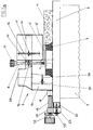
- the table milling machine on which FIGS. 1a, b and 2 are based contains a table 2 which is arranged on a machine frame 1 and which is surmounted by a milling head 3 accommodated on a table-normal shaft, along which a workpiece 4 can be guided for milling an edge contour.
- the workpiece flank to be machined here has a wavy configuration.
- a starting element 5 is therefore provided, on which the workpiece 4 is held in contact with the undulating side flank to be machined during the feed movement.
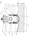
- the starting element 5 is designed as a runner made of plate-shaped material. As best shown in FIG. 2, this has two legs 5a, b inclined at an acute angle, which are connected to one another by an arch 5c. The distance between the edge contour of the starting element 5 and the axis of the milling head 3 is the smallest in the region of the arc 5c. Along the legs 5a, b, this distance increases inwards, that is, in the direction running away from the workpiece 4. When the workpiece 4 rests on the sheet 5c, the result is deepest workpiece engagement. The legs 5a, b prevent a sudden, deeper workpiece insertion and make the use of so-called run-up strips unnecessary.
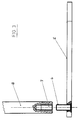
- the runner forming the runner 5 is provided in the region of the ends of the legs 5a, b, as can best be seen in FIG.
- the support rods 8 are screwed onto the plate-shaped thrust member 5 until their lower end face is seated, which results in a stable connection and at the same time an exactly rectangular arrangement.
- the support rods 8 are mounted on an adjustable table top 9 on the table 2 with a degree of freedom of movement in the vertical direction.
- the table attachment 9, as FIGS. 2 and 3 further show, is provided with bearing bushes 10 assigned to the support rods 8, which are penetrated by the respectively assigned support rod 8.
- an actuating head 11 By moving the support rods 8, which are provided at their upper end with an actuating head 11, any desired height position of the starting element 5 can thus be set. As shown in FIG. 1 a, this can be positioned above the milling head 3. Of course, it would also be conceivable to position the starting element 5 below the milling head 3, as shown in FIG. 1b.
- To fix the set position are in the range of Guide bushes 10 provided, with the support rods 8 cooperating clamping screws 12 are provided.
- the guide rods 8 are designed here as round rods with a circular cross-section, so that it is possible to screw the support rod 8 which passes through the respectively assigned guide bushing 10 onto the associated threaded pin 6.
- the actuating button 11 enables a firm suit and simple operation. Unless a camber-shaped starting element is required here, this is simply removed by corresponding actuation of the support rods 8.
- Other guiding elements can then be accommodated on these, for example associated thrust strips associated with a thrust ring received on the machine shaft.
- the table top 9 consists of a sitting on the table 2, partially overlapping the milling head 3, open on the machining side 13, from which a table-parallel extension 14, which is arranged at a table distance and projects over the milling head 3 and partially also the workpiece 4, projects.
- the guide bushes 10 for the support rods 8 are integrated in these.
- the skid-shaped thrust member 5 bridges the clear width of the box 13.
- the guide bushes 10 are therefore located in the region of the lateral flanks of the end of the extension 14 near the box. This ensures that the support rods 8 do not collide with the milling cutter stop 5 positioned under the milling head 3 come the milling head 3, as can be seen in Figure 1b.
- the front carries the workpiece Area of the approach 14 a cover 15 acting as access protection, which blocks access to the processing area.
- the cover 15 is here shell-shaped to the outer contour of the extension 14 and is adjustable in height relative to this.
- the cover panel 15, as can best be seen from FIG. 1, is provided with slots 16 which extend in the direction of the table and into which the clamping screws 17 on the shoulder side engage.
- the entire table attachment 9 can be displaced transversely to the feed direction of the workpiece 4 for the depth adjustment of the starting element 5.
- the table top 9 is connected to the table 2 by means of an actuating and guiding device.
- the actuating and guiding device is accommodated on the table top 9 and can be connected to the table 2 via a plug connection, which enables the entire table top 9 including the associated actuating and guiding device to be easily removed.
- Said actuating and guiding device contains from a reinforcing rail 18 attached to the rear of the box 13 of the table top 9 remote from the workpiece and projecting to the rear guide rods 19 which engage in associated guide bores in a bearing rail 20 parallel to the reinforcing rail 18.
- a threaded rod 21 is provided between the two guide rods 19, which also extends through the bearing rail 20 and interacts with an adjusting nut 22 that can be supported on the bearing rail 20. This is designed as an actuation button.
- the bearing rail 20 is provided with downwardly projecting plug pins 23 which can be inserted into associated recesses in a mounting bracket 24 fastened to the rear side flank of the table 2. Fixing screws 25 can be provided to achieve a play-free fit and to secure the position.
- the table attachment 9 as can be seen from FIG. 2, is provided in the area of the box 13 with slots normal to the feed bars 19 parallel to the feed bars 19, through which clamping screws 27 which can be brought into engagement with the associated threaded bores of the table 2 can be carried out.
- the table top 9 can be moved relative to the table 2 in the direction normal to the feed by actuating the actuating and guiding device.
- the clamping screws 27 are tightened, there is a rigid, play-free connection.
- the box 13 of the table top 9 is provided with an upwardly extending connecting piece 28 for a suction hose.
- brushes 29 are provided on the workpiece, which are adjustable in depth.
- the brush holders are provided with corresponding slots 30 through which the clamping screws 31 on the box side extend.
Landscapes
- Engineering & Computer Science (AREA)
- Life Sciences & Earth Sciences (AREA)
- Mechanical Engineering (AREA)
- Wood Science & Technology (AREA)
- Forests & Forestry (AREA)
- Automation & Control Theory (AREA)
- Milling, Drilling, And Turning Of Wood (AREA)
- Machine Tool Units (AREA)
- Soil Working Implements (AREA)
- Formation And Processing Of Food Products (AREA)
- Table Devices Or Equipment (AREA)
Applications Claiming Priority (2)
| Application Number | Priority Date | Filing Date | Title |
|---|---|---|---|
| DE4429571 | 1994-08-19 | ||
| DE4429571A DE4429571C1 (de) | 1994-08-19 | 1994-08-19 | Holzbearbeitungsmaschine |
Publications (2)
| Publication Number | Publication Date |
|---|---|
| EP0703048A1 true EP0703048A1 (fr) | 1996-03-27 |
| EP0703048B1 EP0703048B1 (fr) | 1998-10-21 |
Family
ID=6526170
Family Applications (1)
| Application Number | Title | Priority Date | Filing Date |
|---|---|---|---|
| EP95112362A Expired - Lifetime EP0703048B1 (fr) | 1994-08-19 | 1995-08-05 | Machine de travail du bois |
Country Status (4)
| Country | Link |
|---|---|
| EP (1) | EP0703048B1 (fr) |
| AT (1) | ATE172400T1 (fr) |
| CZ (1) | CZ287224B6 (fr) |
| DE (2) | DE4429571C1 (fr) |
Citations (8)
| Publication number | Priority date | Publication date | Assignee | Title |
|---|---|---|---|---|
| GB550950A (en) * | 1941-06-26 | 1943-02-02 | James Tweelale | Improvements in guards for wood-working machines |
| CH291579A (de) * | 1949-03-01 | 1953-06-30 | Joos Heintz | Werkstück-Anschlag- und -Führungseinrichtung an Kehlmaschinen. |
| DE1112824B (de) * | 1957-08-09 | 1961-08-17 | Lutz Kg Eugen | Fuehrungsanschlag fuer Fraesmaschinen |
| DE3407243A1 (de) * | 1984-02-28 | 1985-08-29 | Georg 8386 Thannenmais Aigner | Fuehrungsvorrichtung zum bearbeiten bogenfoermiger werkstuecke, insbesondere in fraesmaschinen fuer die holzbearbeitung |
| DE3931141A1 (de) * | 1989-09-19 | 1991-03-28 | Fried Kunststofftechnik Gmbh | Spaeneauffangvorrichtung fuer eine tischfraesmaschine zum fraesen geschweifter werkstuecke aus holz |
| DE4131943C1 (fr) | 1991-09-25 | 1992-09-17 | Georg 8386 Reisbach De Aigner | |
| EP0504375A1 (fr) * | 1990-10-17 | 1992-09-23 | PEDROS BATTLE, Agustin | Dispositif protecteur a geometrie variable pour machines de fa onnage du bois |
| FR2711571A1 (fr) * | 1993-10-29 | 1995-05-05 | Inst Nat Rech Securite | Dispositif de sécurité pour toupie pour travail à l'arbre. |
-
1994
- 1994-08-19 DE DE4429571A patent/DE4429571C1/de not_active Expired - Fee Related
-
1995
- 1995-08-05 EP EP95112362A patent/EP0703048B1/fr not_active Expired - Lifetime
- 1995-08-05 AT AT95112362T patent/ATE172400T1/de not_active IP Right Cessation
- 1995-08-05 DE DE59503978T patent/DE59503978D1/de not_active Expired - Lifetime
- 1995-08-07 CZ CZ19952010A patent/CZ287224B6/cs not_active IP Right Cessation
Patent Citations (8)
| Publication number | Priority date | Publication date | Assignee | Title |
|---|---|---|---|---|
| GB550950A (en) * | 1941-06-26 | 1943-02-02 | James Tweelale | Improvements in guards for wood-working machines |
| CH291579A (de) * | 1949-03-01 | 1953-06-30 | Joos Heintz | Werkstück-Anschlag- und -Führungseinrichtung an Kehlmaschinen. |
| DE1112824B (de) * | 1957-08-09 | 1961-08-17 | Lutz Kg Eugen | Fuehrungsanschlag fuer Fraesmaschinen |
| DE3407243A1 (de) * | 1984-02-28 | 1985-08-29 | Georg 8386 Thannenmais Aigner | Fuehrungsvorrichtung zum bearbeiten bogenfoermiger werkstuecke, insbesondere in fraesmaschinen fuer die holzbearbeitung |
| DE3931141A1 (de) * | 1989-09-19 | 1991-03-28 | Fried Kunststofftechnik Gmbh | Spaeneauffangvorrichtung fuer eine tischfraesmaschine zum fraesen geschweifter werkstuecke aus holz |
| EP0504375A1 (fr) * | 1990-10-17 | 1992-09-23 | PEDROS BATTLE, Agustin | Dispositif protecteur a geometrie variable pour machines de fa onnage du bois |
| DE4131943C1 (fr) | 1991-09-25 | 1992-09-17 | Georg 8386 Reisbach De Aigner | |
| FR2711571A1 (fr) * | 1993-10-29 | 1995-05-05 | Inst Nat Rech Securite | Dispositif de sécurité pour toupie pour travail à l'arbre. |
Also Published As
| Publication number | Publication date |
|---|---|
| ATE172400T1 (de) | 1998-11-15 |
| DE4429571C1 (de) | 1996-01-04 |
| EP0703048B1 (fr) | 1998-10-21 |
| CZ201095A3 (en) | 1996-03-13 |
| CZ287224B6 (en) | 2000-10-11 |
| DE59503978D1 (de) | 1998-11-26 |
Similar Documents
| Publication | Publication Date | Title |
|---|---|---|
| DE102012201736B3 (de) | Universal-Werkzeugmaschine mit Spänesammelraum | |
| DE69619028T2 (de) | Einstellbarer Anschlag für eine Kapp- und Gehrungssäge | |
| EP0144490A2 (fr) | Dispositif de guidage de foreuse ou fraise pour machines échangeables d'entraînement | |
| EP0565050A1 (fr) | Tête de fraisage | |
| EP0558692B1 (fr) | Dispositif de protection et de guidage pour fraiseuses a bois--- | |
| DE4243054C1 (de) | Vorrichtung zur Bearbeitung der Kantenränder von fortlaufend bewegten plattenförmigen Werkstücken | |
| DE3716057A1 (de) | Fuehrungsvorrichtung fuer elektrowerkzeuge | |
| WO1993023199A1 (fr) | Capot de protection pour machines-outils a travailler le bois | |
| DE9307192U1 (de) | Stationär betriebene Auslegerkreissäge | |
| DE3333169C2 (fr) | ||
| EP0235683A2 (fr) | Machine à travailler le bois | |
| DE4429571C1 (de) | Holzbearbeitungsmaschine | |
| DE2719979C2 (de) | Fräs-Vorsatzgerät für Heimwerker- Bohrmaschinen | |
| DE2951355A1 (de) | Rolltisch fuer holzbearbeitungsmaschinen | |
| EP0118077B1 (fr) | Butée à onglets | |
| DE8222914U1 (de) | Maschinenwerkzeug, insbesondere fraesmaschine | |
| EP0082446B1 (fr) | Tour pour bois | |
| DE19739269C1 (de) | Spannvorrichtung, insbesondere Maschinenschraubstock | |
| DE4413483A1 (de) | Aufsatzgerät für eine Werkzeugschleifmaschine | |
| DE3333624C2 (fr) | ||
| DE3341158C2 (fr) | ||
| DE29511233U1 (de) | Kleine Fräsmaschine | |
| EP0167112A1 (fr) | Procédé et appareil pour fraiser et rainurer des parties d'un cadre en bois | |
| DE4443189C2 (de) | Säge | |
| EP0210555A1 (fr) | Tête d'usinage |
Legal Events
| Date | Code | Title | Description |
|---|---|---|---|
| PUAI | Public reference made under article 153(3) epc to a published international application that has entered the european phase |
Free format text: ORIGINAL CODE: 0009012 |
|
| AK | Designated contracting states |
Kind code of ref document: A1 Designated state(s): AT DE FR GB IT |
|
| 17P | Request for examination filed |
Effective date: 19960718 |
|
| 17Q | First examination report despatched |
Effective date: 19970312 |
|
| GRAG | Despatch of communication of intention to grant |
Free format text: ORIGINAL CODE: EPIDOS AGRA |
|
| GRAH | Despatch of communication of intention to grant a patent |
Free format text: ORIGINAL CODE: EPIDOS IGRA |
|
| GRAH | Despatch of communication of intention to grant a patent |
Free format text: ORIGINAL CODE: EPIDOS IGRA |
|
| GRAA | (expected) grant |
Free format text: ORIGINAL CODE: 0009210 |
|
| AK | Designated contracting states |
Kind code of ref document: B1 Designated state(s): AT DE FR GB IT |
|
| REF | Corresponds to: |
Ref document number: 172400 Country of ref document: AT Date of ref document: 19981115 Kind code of ref document: T |
|
| REF | Corresponds to: |
Ref document number: 59503978 Country of ref document: DE Date of ref document: 19981126 |
|
| GBT | Gb: translation of ep patent filed (gb section 77(6)(a)/1977) |
Effective date: 19981123 |
|
| ET | Fr: translation filed | ||
| PLBE | No opposition filed within time limit |
Free format text: ORIGINAL CODE: 0009261 |
|
| STAA | Information on the status of an ep patent application or granted ep patent |
Free format text: STATUS: NO OPPOSITION FILED WITHIN TIME LIMIT |
|
| 26N | No opposition filed | ||
| REG | Reference to a national code |
Ref country code: GB Ref legal event code: IF02 |
|
| PGFP | Annual fee paid to national office [announced via postgrant information from national office to epo] |
Ref country code: FR Payment date: 20090703 Year of fee payment: 15 |
|
| PGFP | Annual fee paid to national office [announced via postgrant information from national office to epo] |
Ref country code: GB Payment date: 20090706 Year of fee payment: 15 Ref country code: DE Payment date: 20090702 Year of fee payment: 15 Ref country code: AT Payment date: 20090703 Year of fee payment: 15 |
|
| PGFP | Annual fee paid to national office [announced via postgrant information from national office to epo] |
Ref country code: IT Payment date: 20090812 Year of fee payment: 15 |
|
| GBPC | Gb: european patent ceased through non-payment of renewal fee |
Effective date: 20100805 |
|
| REG | Reference to a national code |
Ref country code: FR Ref legal event code: ST Effective date: 20110502 |
|
| PG25 | Lapsed in a contracting state [announced via postgrant information from national office to epo] |
Ref country code: AT Free format text: LAPSE BECAUSE OF NON-PAYMENT OF DUE FEES Effective date: 20100805 Ref country code: IT Free format text: LAPSE BECAUSE OF NON-PAYMENT OF DUE FEES Effective date: 20100805 |
|
| REG | Reference to a national code |
Ref country code: DE Ref legal event code: R119 Ref document number: 59503978 Country of ref document: DE Effective date: 20110301 |
|
| PG25 | Lapsed in a contracting state [announced via postgrant information from national office to epo] |
Ref country code: FR Free format text: LAPSE BECAUSE OF NON-PAYMENT OF DUE FEES Effective date: 20100831 Ref country code: DE Free format text: LAPSE BECAUSE OF NON-PAYMENT OF DUE FEES Effective date: 20110301 |
|
| PG25 | Lapsed in a contracting state [announced via postgrant information from national office to epo] |
Ref country code: GB Free format text: LAPSE BECAUSE OF NON-PAYMENT OF DUE FEES Effective date: 20100805 |