EP0703341B1 - Sicherheitsbehälterzusammenbau - Google Patents
Sicherheitsbehälterzusammenbau Download PDFInfo
- Publication number
- EP0703341B1 EP0703341B1 EP95830393A EP95830393A EP0703341B1 EP 0703341 B1 EP0703341 B1 EP 0703341B1 EP 95830393 A EP95830393 A EP 95830393A EP 95830393 A EP95830393 A EP 95830393A EP 0703341 B1 EP0703341 B1 EP 0703341B1
- Authority
- EP
- European Patent Office
- Prior art keywords
- safety
- carrousel
- box assembly
- safety box
- assembly
- Prior art date
- Legal status (The legal status is an assumption and is not a legal conclusion. Google has not performed a legal analysis and makes no representation as to the accuracy of the status listed.)
- Expired - Lifetime
Links
Images

Classifications
-
- E—FIXED CONSTRUCTIONS
- E05—LOCKS; KEYS; WINDOW OR DOOR FITTINGS; SAFES
- E05G—SAFES OR STRONG-ROOMS FOR VALUABLES; BANK PROTECTION DEVICES; SAFETY TRANSACTION PARTITIONS
- E05G1/00—Safes or strong-rooms for valuables
- E05G1/06—Safes or strong-rooms for valuables having provision for multiple compartments
Definitions
- the present invention relates to a safety box assembly.
- the invention concerns an assembly allowing to include a rather high number of safety boxes in a limited space, further allowing the individual managing of the same in the maximum safety and flexibility conditions.
- an automatic management system for safety boxes is provided, said system allowing to the user to autonomously manage a safety box space contained within an armour-plated structure placed in the opening of a suitable space of a bank, post office, railway station, hotel, etc.
- this kind of solution involves the very long routine of accompanying the client within the vault, and opening and closing the box with two keys, so that the management of the safety boxes is not so much advantageous.
- the solution adopted provides traditional boxes placed in a suitable room from which robotized mechanical arms remove and transport the boxes near to the space destined to the client.
- the solution proposed according to the present invention is included in this context, said solution allowing to overcome the above mentioned drawbacks, giving at the same time a modern, safe and easily self-manageable service that occupies a little space and requires investments ammortizable in a short time.
- EP-A-0140839 which is the most pertinent prior art document, discloses a safety box having the features included in the precharacterizing portion of the enclosed claim 1.
- the safety box assembly according to the invention is characterized by the features included in the characterizing portion of claim 1.
- a safety box assembly comprising a cylindrical revolving carrousel divided in sectors with a box bearing opening, motion means for an access door and computer means, said assembly being characterized in that said cylindrical revolving carrousel is made up of at least one floor, in that each floor comprises at least a false armour-plated opening and in that it further comprises an outer armour plated structure, provided with a number of movable doors corresponding to the number of floors provided on the carrousel, in order to allow the access to the box bearing openings of each floor, a control terminal allowing to the user to interact with the assembly and motion means for the carrousel floors, said computer means being provided with a suitable software, to control said motion means on the basis of the instructions introduced within the control terminal.
- said carrousel comprises a plurality of floors that can be all provided with equal sectors with box bearing opening or they can be realized with different sectors, so that the carrousel has safety boxes of different sizes, said access doors being provided in number and sizes corresponding to the floors and to the kind of openings provided in each floor.
- said sectors with box bearing opening provide fixed boxes or removable boxes that can be introduced within the opening.
- each one of said boxes is provided with a safety lock of the expansion piles kind.
- Said false opening of each floor is preferably closed by a steel plate.
- the armour-plated structure is preferably comprised of a steel frame, with an internally bolted panels and with an armour-plated door for the access to the carrousel for its maintenance, the motion means of the carrousel being provided above the armour-plated structure.
- each one of said doors is moved by a ratiomotor connected with said computer means, provided with safety means locking the closure of the door in case of any impediment.
- said safety means can be made up of a spring and release joint.
- each one of said doors further safety means can be provided, particularly a photoelectric cell.
- the control terminal directly connected to the computer means, will preferably comprise a keyboard, and/or a magnetic card reader and/or a display.
- said motion means of the carrousel can be comprised of a ratiomotor, connected with the rotation axis of the carrousel, by a gear and chain system and an electromechanical decoder, a control logic card and safety system control cards.
- the access to the safety box of the user is subordinated to the introduction of three codes, one of which is directly set out by the user, the assembly providing that each time an operation is finished the armour-plated false opening is brought in correspondence of the relevant door.
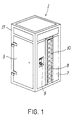
- the safety box assembly is comprised of a steel structure sheathed with armour-plated panels.
- Said armour-plated panels are internally fixed by bolts so that externally it is impossible to act on the bolts to force the assembly 1.
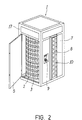
- a cylindrical carrousel 2 provided with more than one floor is housed, said carrousel being divided in sectors - openings suitable to contain the safety boxes 3, as well as a row of false openings 4, that will be described in greater detail in the following.
- the access to the carrousel 2 is possible through an access armour-plated door 5.
- Each one of the safety boxes is provided with a frontal element having a safety lock with vertical expansion piles.
- One of the walls of the steel structure specifically the wall 7, provides a row of superimposed access doors 8, in order to be able to have access to the single boxes 3, according to the formality that will be described in the following.
- a keyboard 9 with display or control terminal is provided.
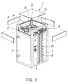
- Each one of the doors 8 is realized with vertical frames having an accident prevention photoelectric cell 10 that in case of any kind of obstacle, due for example to fingers or hands, stops the closure of the door that will go back in order to repeat after the operation.
- a ratiomotor 11 for the motion of the rotation axis 12 of the carrousel 2, by gears 13 connected by a chain, is shown.
- the steel structure comprises a strong steel frame 17, upon which panels are mounted, said panels being, as already said, innerly fixed by bolts.
- the armour-plated door 5 allows to access within the structure to make the maintenance of the opening automatism of the outer doors 8.
- the sectors - openings for the safety boxes 3 have a trapezoidal shape and are placed on different floors of the revolving carrousel 2. Obviously, the number of the floors can be varied and the same floors can all have the same height or different heights according to the cases, with the number of sectors for each floor variable in function of the needing and of the kind of box; further, also the boxes 3 can be all the same or they can be different.
- the false opening 4 sector of the floor cannot be used as safety box bearing sector and is frontally closed by a steel plate.
- each floor is divided in 24 sectors, 23 of which form the box 3 openings, while the last one is the safety sector that will be placed behind the row of superimposed doors 8 when the assembly 1 is in the rest position.
- the dimensions of the doors 8 correspond to those of the box 3 bearing openings of the relevant whole floor.
- the door 8 made up of a very thick steel plate, opens and closes laterally sliding within the wall 7, by an automated and software managed control.
- the mechanisation of each door 8 is comprised of an endless screw operated by a ratiomotor 19 by a spring and release joint 20.
- Each box 3 is provided with a safety lock 6 having vertical offset expansion piles, said piles fixing in the structure of the carrousel 2. Therefore, each box 3 opening can be considered as a little safe.
- the motor is operated by the PLC logic card 15 by a command sent by the personal computer, after that the computer has checked that the data digitised on the keyboard 9 correspond to the combination of the three data previously stored within its memory.
- the electromechanical decoder 14 by means of a position reader 21, allows the stop of the motor and thus the motion of the carrousel 2, when the sector indicated by the user by the control terminal 9 is placed in correspondence of the row of doors 8 opening on the front side of the wall 7.
- the PLC logic card 15 operates the ratiomotor 19 corresponding to the indicated floor, said ratiomotor opening, by an endless screw 18, the door 8 horizontally slidable.
- the logic card 15 upon indication of the personal computer, starts again the ratiomotor 19 to close again the door 8 by the endless screw 18.
- said screw 18 is connected with the axis of the ratiomotor 19 by means of a spring and release joint 20 (clutch), moving in an "idle” position in case during the closure the door 8 encounters any obstacle; during the release motion of the joint (idle clutch) also a microswitch inverting the rotation direction of the ratiomotor 19 is operated.
- the personal computer by the PLC logic card 15 starts again the ratiomotor 11 which moves the carrousel 2 bringing the safety sector again behind the row of doors 8, i.e. the sector with the false openings 4 closed by the steel plate.
- All the working of the assembly according to the present invention is managed by the software which, by a personal computer (not shown) and the logic card 15 (PLC) makes the operations being activated after having recognised the data set out by the user on the keyboard 9 with display.
- PLC logic card 15
- All the managing sector of the safety box assembly, except for the keyboard, is provided in the upper part of the steel structure, well separated from the below sector containing the carrousel 2 with the box 3 bearing openings, so that any eventual maintenance intervention (excluded the replacement of the ratiomotors 19 for the automation of the doors 8) can be carried out without having access to the inner sector and thus without the need of opening the armour-plated door 5.
- the user is able to open the box 3 by the key he already has.
- the user closes the box 3, withdraws the key and pushes on the end of operation button of the keyboard 9.
- the system provides to close again the door 8 and to bring back the user box in the safe position, leaving false openings 4 provided with steel plate behind the doors 8.
- the system will provide to close the door in any case and to bring back the box 3 opening in a safe position.
- the management software makes a complete control of the system every 10 minutes, indicating by an alarm eventual working irregularities.
- This alarm system even remote, operates in any case for any irregularity.
- the solution proposed according to the present invention allows to reach a remarkable series of important advantages with respect to the solutions available up to now.
- the safety box assembly according to the invention allows to obtain the following advatages:
Landscapes
- Lock And Its Accessories (AREA)
- Casings For Electric Apparatus (AREA)
- Power-Operated Mechanisms For Wings (AREA)
- Non-Portable Lighting Devices Or Systems Thereof (AREA)
- Electrical Discharge Machining, Electrochemical Machining, And Combined Machining (AREA)
Claims (13)
- Sicherheitsfächteranordnung (1) mit einem zylinderförmigen Drehkarussel (2), das in Abschnitte mit Fächter (3) enthaltenden Öffnungen unterteilt ist, Betätigungsmitteln für eine Zugangstür (5) und mit Rechnermitteln, dadurch geknnzeichnet, dass das genannte zylinderförmige Drehkarussel aus mindstens einem Stock besteht, das jeder Stock mindstens eine falsche gepanzerte Öffnung (4) aufweist und dass es ausserdem einen gepanzerten äusseren Bauwerk enthält, der mit einer der Anzahl von Stocken entsprechende Anzahl von beweglichen Türen (8) versehen ist, um den Zugang zu den die Fächter enthaltenden Öffnungen eines jeden Stockes zu gestatten, und mit einer Steueranodnung für Benützer zur Steuerung des Karussels und der Stellmittel zur Verstellung der Karussel-Stockewerke, wobei die genannten Rechnermittel mit angebrachten Softwarestücken versehen sind, die zur Steuerung der genannten Stellmittel auf Grund der in die Steueranordnung eingeführten Anweisungen dienen.
- Sicherheitsfächteranordnung (1) nach Anspruch 1, dadurch gekennzeichnet, dass das genannte Karussel (2) eine Mehrzahl von Stockwerken aufweist, die mit Abschniten von Öffnungen für gleiche Fächter (3) oder mit unterschiellichen Abschniten versehen sind, so dass das Karussel (2) auch Sicherheitsfächter (3) unterschiedlicher Grössen haben kann, wobei die gennten Zugangstüre in einer den Stockwerken und der Art der am jeden Stockwerk vorgesehenen Öffnungen entsprechenden Anzahl und Grösse angeordnet sind.
- Sicherheitsfächteranordnung (1) nach je einem der vorhergehenden Ansprüche, dadurch gekennzeichnet, dass die vorgenannten Abschnitte mit Sicherheitsfächter (3) enthaltenden Öffnungen mit festen Fächter (3) versehen sind.
- Sicherheitsfächteranordnung (1) nach Ansprüche 1 oder 2, dadurch gekennzeichnet, dass die vorgenannten Abschnitte, mit Sicherheitsfächter (3) enthaltenden Öffnungen, mit abnehmbaren Fächter (3) versehen sind.
- Sicherheitsfächteranordnung (1) nach je einem der vorhergehenden Ansprüche, dadurch gekennzeichnet, dass die vorgenannten Fächter (3) mit einem Sicherheitsschloss der Art mit Expansionsstäben versehen sind.
- Sicherheitsfächteranordnung (1) nach je einem der vorhergehenden Ansprüche, dadurch gekennzeichnet, dass die genannte falsche Öffnung (4) jedes Stockwerkes mit einer Stahlplatte geschlossen ist.
- Sicherheitsfächteranordnung (1) nach je einem der vorhergehenden Ansprüche, dadurch gekennzeichnet, dass das vorgenannte gepanzerte Aussenbauwerk einen Stahlrahmen (17) enthält, mit innerlich verschraubten Tafeln und einer gepanzerten Tür für den Zugang an das Karussel zur Wartung desselben, wobei die Stellmittel (11,12,13,14,15,16) des Karussels oberhalb des gepanzerten Baurweks angeodnet sind.
- Sicherheitsfächteranordnung (1) nach je einem der vorhergehenden Ansprüche, dadurch gekennzeichnet, dass die vorgenannte Türe (8) durch einen mit den vorgenannten Rechnermitteln verbundenen Getriebe-Motor (19) betätigt wird, der mit Sicherheitsmitteln zur Verriegelung des Schlosses der Tür (8) im Bedartsfall versehen ist.
- Sicherheitsfächteranordnung (1) nach je einem der vorhergehenden Ansprüche, dadurch gekennzeichnet, dass die vorgenannten Sicherheitsmitell aus einer Feder- und Rastkupplung (20) bestehen.
- Sicherheitsfächteranordnung (1) nach Anspruch 9, dadurch gekennzeichnet, dass zu jeder Tür (8) weitere Sicherheitsmitell, insbesondere eine photoelektrische Zelle (10), zugeordnet sind.
- Sicherheitsfächteranordnung (1) nach je einem der vorhergehenden Ansprüche, dadurch gekennzeichnet, dass die mit den Rechnermitteln unmittebar verbundene Steueranordnung eine Tastatur (9) und/oder einen Leser für magnetische Karte oder Display enthält.
- Sicherheitsfächteranordnung (1) nach je einem der vorhergehenden Ansprüche, dadurch gekennzeichnet, dass die genannten Stellmittel des Karussels mit einem Getriebemotor (11), der durch ein Getriebe (13) und eine Ketteanordnung mit der Drehachse (12) des Karussels (2) verbunden ist und mit einen elektromechanischen Entschlüssler, einer logischen Kontrollkarte un mit Sicherheitssystem-Kontrollkarten (16) versehen sind.
- Sicherheitsfächteranordnung (1) nach je einem der vorhergehenden Ansprüche, dadurch gekennzeichnet, dass der Zugang zum Sicherheitsfach des Benützers durch die Einführung von drei Kode-Sohlüsseln freigestellt wird, deren einer unmittelbar vom Benützer gebraucht wird, wobei die Anordnung so getroffen ist, das am Ende einer Operation, die gepanzerte falsche Öffnung an die entsprechende Tür gebracht wird.
Applications Claiming Priority (2)
| Application Number | Priority Date | Filing Date | Title |
|---|---|---|---|
| ITRM940611A IT1274929B (it) | 1994-09-26 | 1994-09-26 | Complesso di cassette di sicurezza |
| ITRM940611 | 1994-09-26 |
Publications (2)
| Publication Number | Publication Date |
|---|---|
| EP0703341A1 EP0703341A1 (de) | 1996-03-27 |
| EP0703341B1 true EP0703341B1 (de) | 2000-05-03 |
Family
ID=11402742
Family Applications (1)
| Application Number | Title | Priority Date | Filing Date |
|---|---|---|---|
| EP95830393A Expired - Lifetime EP0703341B1 (de) | 1994-09-26 | 1995-09-25 | Sicherheitsbehälterzusammenbau |
Country Status (4)
| Country | Link |
|---|---|
| EP (1) | EP0703341B1 (de) |
| AT (1) | ATE192542T1 (de) |
| DE (1) | DE69516613D1 (de) |
| IT (1) | IT1274929B (de) |
Families Citing this family (7)
| Publication number | Priority date | Publication date | Assignee | Title |
|---|---|---|---|---|
| US6587031B1 (en) * | 1997-06-13 | 2003-07-01 | Cash America International, Inc. | Secure storage of high value items |
| AUPO742697A0 (en) * | 1997-06-18 | 1997-07-10 | Australian Postal Corporation | A lock controlled multi-conpartment storage and retrievable device |
| DE19754110C2 (de) * | 1997-12-05 | 2002-02-21 | Leicher Gmbh & Co | Schließfachanlage |
| FR2883908B1 (fr) * | 2005-03-31 | 2008-08-08 | Kereva Entpr Unipersonnelle A | Procede de limitation de l'accessibilite aux composants internes d'une borne a acces public, borne adaptee |
| WO2008055364A1 (en) * | 2006-11-06 | 2008-05-15 | Florent Pelletier | Article management system |
| DE102008019233A1 (de) * | 2008-03-10 | 2009-09-17 | Wincor Nixdorf International Gmbh | Vorrichtung zur Einzahlung und Auszahlung von Bargeld |
| CN112282568A (zh) * | 2020-10-29 | 2021-01-29 | 江西德沃箱柜制造有限公司 | 一种保险柜 |
Family Cites Families (2)
| Publication number | Priority date | Publication date | Assignee | Title |
|---|---|---|---|---|
| IL64015A (en) * | 1980-10-24 | 1984-10-31 | Pretini Gisberto | Automated bank counter |
| CH654874A5 (de) * | 1983-10-31 | 1986-03-14 | Georges R Locher | Safe-anlage. |
-
1994
- 1994-09-26 IT ITRM940611A patent/IT1274929B/it active IP Right Grant
-
1995
- 1995-09-25 EP EP95830393A patent/EP0703341B1/de not_active Expired - Lifetime
- 1995-09-25 DE DE69516613T patent/DE69516613D1/de not_active Expired - Lifetime
- 1995-09-25 AT AT95830393T patent/ATE192542T1/de not_active IP Right Cessation
Also Published As
| Publication number | Publication date |
|---|---|
| ITRM940611A1 (it) | 1996-03-26 |
| ATE192542T1 (de) | 2000-05-15 |
| EP0703341A1 (de) | 1996-03-27 |
| DE69516613D1 (de) | 2000-06-08 |
| IT1274929B (it) | 1997-07-29 |
| ITRM940611A0 (it) | 1994-09-26 |
Similar Documents
| Publication | Publication Date | Title |
|---|---|---|
| US5979750A (en) | Computerized delivery acceptance system | |
| US4974257A (en) | Modular public telephone for outside use | |
| US5758522A (en) | Access control system for security enclosure | |
| US5794466A (en) | Key safe for housing a key | |
| EP0703341B1 (de) | Sicherheitsbehälterzusammenbau | |
| WO1994012749A1 (en) | Key safe for housing a key | |
| EP0051048B1 (de) | Automatisiertes Bankhinterlegungssystem | |
| US4704880A (en) | Removable cam-lock unit and dead-bolt mechanism | |
| RU2040690C1 (ru) | Сейф | |
| CA1118643A (en) | Armor plated safe | |
| US11371260B2 (en) | Mechanical lock with discriminated opening via control for a plurality of keys that can be authorized and system for receiving parcels that includes same | |
| NL8501907A (nl) | Inrichting voor het electronisch sturen en bewaken van meerdere sloten. | |
| CN215169439U (zh) | 一种智能联网防盗门 | |
| AU2838997A (en) | Access control devices and systems including same | |
| NL9202032A (nl) | Gecompartimenteerde kluis. | |
| GB2388154A (en) | Locking apparatus with key retention | |
| EP0082169B1 (de) | Sicherheitsmechanismus zur verhinderung des einsperrens von personen in kammern | |
| EP1152376A2 (de) | Vorrichtung zum Ermöglichen der sicheren Abgabe und/oder des sicheren Sammelns von Gütern unter Verwendung eines einmaligen Zugangscodes | |
| CN220849211U (zh) | 一种具有破坏提醒效果的小区安防门禁结构 | |
| GB2301142A (en) | An electronic lock | |
| EP0000744B1 (de) | Panzerschrank zur Aufbewahrung von Schlüsseln | |
| RU2200447C2 (ru) | Шкафчик, в частности, для гостиниц, плавательных бассейнов и подобных объектов | |
| US3231693A (en) | Card-operated lock controller | |
| CN215761317U (zh) | 一种储藏柜式防盗门 | |
| EP1770735B1 (de) | Sicherheitsschalter |
Legal Events
| Date | Code | Title | Description |
|---|---|---|---|
| PUAI | Public reference made under article 153(3) epc to a published international application that has entered the european phase |
Free format text: ORIGINAL CODE: 0009012 |
|
| AK | Designated contracting states |
Kind code of ref document: A1 Designated state(s): AT CH DE ES FR LI |
|
| 17P | Request for examination filed |
Effective date: 19960607 |
|
| 17Q | First examination report despatched |
Effective date: 19990212 |
|
| GRAG | Despatch of communication of intention to grant |
Free format text: ORIGINAL CODE: EPIDOS AGRA |
|
| GRAG | Despatch of communication of intention to grant |
Free format text: ORIGINAL CODE: EPIDOS AGRA |
|
| GRAH | Despatch of communication of intention to grant a patent |
Free format text: ORIGINAL CODE: EPIDOS IGRA |
|
| GRAH | Despatch of communication of intention to grant a patent |
Free format text: ORIGINAL CODE: EPIDOS IGRA |
|
| GRAA | (expected) grant |
Free format text: ORIGINAL CODE: 0009210 |
|
| AK | Designated contracting states |
Kind code of ref document: B1 Designated state(s): AT CH DE ES FR LI |
|
| PG25 | Lapsed in a contracting state [announced via postgrant information from national office to epo] |
Ref country code: LI Free format text: LAPSE BECAUSE OF FAILURE TO SUBMIT A TRANSLATION OF THE DESCRIPTION OR TO PAY THE FEE WITHIN THE PRESCRIBED TIME-LIMIT Effective date: 20000503 Ref country code: FR Free format text: LAPSE BECAUSE OF FAILURE TO SUBMIT A TRANSLATION OF THE DESCRIPTION OR TO PAY THE FEE WITHIN THE PRESCRIBED TIME-LIMIT Effective date: 20000503 Ref country code: ES Free format text: THE PATENT HAS BEEN ANNULLED BY A DECISION OF A NATIONAL AUTHORITY Effective date: 20000503 Ref country code: CH Free format text: LAPSE BECAUSE OF FAILURE TO SUBMIT A TRANSLATION OF THE DESCRIPTION OR TO PAY THE FEE WITHIN THE PRESCRIBED TIME-LIMIT Effective date: 20000503 Ref country code: AT Free format text: LAPSE BECAUSE OF FAILURE TO SUBMIT A TRANSLATION OF THE DESCRIPTION OR TO PAY THE FEE WITHIN THE PRESCRIBED TIME-LIMIT Effective date: 20000503 |
|
| REF | Corresponds to: |
Ref document number: 192542 Country of ref document: AT Date of ref document: 20000515 Kind code of ref document: T |
|
| REG | Reference to a national code |
Ref country code: CH Ref legal event code: EP |
|
| REF | Corresponds to: |
Ref document number: 69516613 Country of ref document: DE Date of ref document: 20000608 |
|
| PG25 | Lapsed in a contracting state [announced via postgrant information from national office to epo] |
Ref country code: DE Free format text: LAPSE BECAUSE OF FAILURE TO SUBMIT A TRANSLATION OF THE DESCRIPTION OR TO PAY THE FEE WITHIN THE PRESCRIBED TIME-LIMIT Effective date: 20000804 |
|
| EN | Fr: translation not filed | ||
| REG | Reference to a national code |
Ref country code: CH Ref legal event code: PL |
|
| PLBE | No opposition filed within time limit |
Free format text: ORIGINAL CODE: 0009261 |
|
| STAA | Information on the status of an ep patent application or granted ep patent |
Free format text: STATUS: NO OPPOSITION FILED WITHIN TIME LIMIT |
|
| 26N | No opposition filed |