EP0703375B1 - Zweiteilige Druckscheibe - Google Patents
Zweiteilige Druckscheibe Download PDFInfo
- Publication number
- EP0703375B1 EP0703375B1 EP95113912A EP95113912A EP0703375B1 EP 0703375 B1 EP0703375 B1 EP 0703375B1 EP 95113912 A EP95113912 A EP 95113912A EP 95113912 A EP95113912 A EP 95113912A EP 0703375 B1 EP0703375 B1 EP 0703375B1
- Authority
- EP
- European Patent Office
- Prior art keywords
- raceway
- raceway portion
- thrust washer
- piece thrust
- washer according
- Prior art date
- Legal status (The legal status is an assumption and is not a legal conclusion. Google has not performed a legal analysis and makes no representation as to the accuracy of the status listed.)
- Expired - Lifetime
Links
- 229910000831 Steel Inorganic materials 0.000 claims description 7
- 239000010959 steel Substances 0.000 claims description 7
- 239000000463 material Substances 0.000 claims description 6
- 238000000034 method Methods 0.000 claims description 6
- 238000005304 joining Methods 0.000 claims description 3
- 230000014759 maintenance of location Effects 0.000 claims description 3
- 238000010276 construction Methods 0.000 description 3
- 238000004519 manufacturing process Methods 0.000 description 3
- 230000005540 biological transmission Effects 0.000 description 2
- 238000005336 cracking Methods 0.000 description 2
- 238000010438 heat treatment Methods 0.000 description 2
- OKTJSMMVPCPJKN-UHFFFAOYSA-N Carbon Chemical compound [C] OKTJSMMVPCPJKN-UHFFFAOYSA-N 0.000 description 1
- 229910000760 Hardened steel Inorganic materials 0.000 description 1
- 229910001209 Low-carbon steel Inorganic materials 0.000 description 1
- 229910000699 SAE 1074 Inorganic materials 0.000 description 1
- 230000003466 anti-cipated effect Effects 0.000 description 1
- 229910052799 carbon Inorganic materials 0.000 description 1
- 230000000694 effects Effects 0.000 description 1
- 229920000642 polymer Polymers 0.000 description 1
- 230000000717 retained effect Effects 0.000 description 1
Images

Classifications
-
- F—MECHANICAL ENGINEERING; LIGHTING; HEATING; WEAPONS; BLASTING
- F16—ENGINEERING ELEMENTS AND UNITS; GENERAL MEASURES FOR PRODUCING AND MAINTAINING EFFECTIVE FUNCTIONING OF MACHINES OR INSTALLATIONS; THERMAL INSULATION IN GENERAL
- F16C—SHAFTS; FLEXIBLE SHAFTS; ELEMENTS OR CRANKSHAFT MECHANISMS; ROTARY BODIES OTHER THAN GEARING ELEMENTS; BEARINGS
- F16C33/00—Parts of bearings; Special methods for making bearings or parts thereof
- F16C33/30—Parts of ball or roller bearings
- F16C33/58—Raceways; Race rings
- F16C33/60—Raceways; Race rings divided or split, e.g. comprising two juxtaposed rings
-
- F—MECHANICAL ENGINEERING; LIGHTING; HEATING; WEAPONS; BLASTING
- F16—ENGINEERING ELEMENTS AND UNITS; GENERAL MEASURES FOR PRODUCING AND MAINTAINING EFFECTIVE FUNCTIONING OF MACHINES OR INSTALLATIONS; THERMAL INSULATION IN GENERAL
- F16C—SHAFTS; FLEXIBLE SHAFTS; ELEMENTS OR CRANKSHAFT MECHANISMS; ROTARY BODIES OTHER THAN GEARING ELEMENTS; BEARINGS
- F16C19/00—Bearings with rolling contact, for exclusively rotary movement
- F16C19/22—Bearings with rolling contact, for exclusively rotary movement with bearing rollers essentially of the same size in one or more circular rows, e.g. needle bearings
- F16C19/30—Bearings with rolling contact, for exclusively rotary movement with bearing rollers essentially of the same size in one or more circular rows, e.g. needle bearings for axial load mainly
-
- F—MECHANICAL ENGINEERING; LIGHTING; HEATING; WEAPONS; BLASTING
- F16—ENGINEERING ELEMENTS AND UNITS; GENERAL MEASURES FOR PRODUCING AND MAINTAINING EFFECTIVE FUNCTIONING OF MACHINES OR INSTALLATIONS; THERMAL INSULATION IN GENERAL
- F16C—SHAFTS; FLEXIBLE SHAFTS; ELEMENTS OR CRANKSHAFT MECHANISMS; ROTARY BODIES OTHER THAN GEARING ELEMENTS; BEARINGS
- F16C33/00—Parts of bearings; Special methods for making bearings or parts thereof
- F16C33/30—Parts of ball or roller bearings
- F16C33/58—Raceways; Race rings
- F16C33/588—Races of sheet metal
Definitions
- the present invention relates generally to thrust washers and, more particularly, to a two-piece construction for a thrust washer and method of connecting together the two pieces of the thrust washer.
- thrust washers that are piloted or mounted on surfaces that are radially spaced a considerable distance from the bearing raceway.
- Such thrust washers may be considered as having a large cross-sectional area relative to the bearing raceway area.
- the non-raceway portion of the thrust washer may have a simple circular perimeter or may have a complex geometry including locking tabs, for example, making manufacture more difficult. See e.g. the document US-A-3 999 816.
- thrust washers of this type are manufactured of a single material, such as bearing quality steel, for example, due to the requirements of the raceway portion.
- Heat treating of the thrust washer is generally required to achieve a suitable raceway.
- warping, cracking and other problems may occur in either the raceway or non-raceway portions.
- An additional problem is the high material cost due to the use of bearing quality steel rather than a less expensive material for the non-raceway portion.
- a two-piece thrust washer comprising a raceway portion and a non-raceway portion as defined in claim 1.
- the raceway portion has a radially directed raceway for rollers, and the non-raceway portion extends radially outward from the raceway portion for engagement with a piloting surface.
- Mechanical means formed integrally on the raceway and non-raceway portions, joins the raceway portion and the non-raceway portion together.
- this is accomplished by providing a method for assembling a two-piece thrust washer as defined in claim 9.
- FIGS. 1 and 2 illustrate raceway portion 10 of a two-piece thrust washer made in accordance with the present invention.
- Raceway surface 12 extends radially outward from axially extending lip 14, forming circular opening 16.
- Notches 22 provide stress relief and facilitate flexing of locking tabs 18.
- Figure 3 illustrates non-raceway portion 24 having a complex configuration including three pairs of locking fingers 26, equally spaced along its perimeter for locking engagement with a piloting surface of an automobile transmission, not shown.
- Locking fingers 26 include barb portions 28 and are separated by T-shaped openings 30 for increased flexibility.
- Three arcuate slots 32, equally spaced circumferentially about circular central opening 34, have a length and radial distance from central opening 34 so as to receive locking tabs 18 of raceway portion 10.
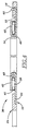
- Figure 4 illustrates two-piece thrust washer 36, shown in longitudinal section, made in accordance with the present invention and including raceway portion 10 and non-raceway portion 24 of Figures 1 through 3.
- Figure 4 shows needle rollers 38, bearing retainer 40, and second thrust washer 42, each being conventional, mounted on two-piece thrust washer 36 to form a thrust bearing assembly.
- hook portions 20 may have angled end surfaces 44 that engage a surface of non-raceway portion 24 forming arcuate slots 32 to wedge locking tabs 18 radially outward.
- two of the locking tabs 18 may be inserted to a locked position in arcuate slots 32 first, and forced radially inward such that the third locking tab 18 more easily deflects radially outward during assembly.
- bearing retainer 40 with needle rollers 38 is snapped on to raceway surface of the second thrust washer 42.
- this sub-assembly including second thrust washer 42 bearing retainer 40 and needle rollers 38 is snapped on to raceway 12, as shown in Figure 4.
- Axially extending lip 46 of second thrust washer 42 extends between lip 14 of raceway portion 10 and bearing retainer 40.
- lip 14 is mechanically retained to second thrust washer 42 by three stake point locations 48 to retain the elements as an assembly while allowing free relative rotation of two-piece thrust washer 36 and second thrust washer 42.
- raceway portion 10 is formed of bearing quality steel, AISI 1074 steel, for example, and is heat treated to a through-hard condition according to current methods for manufacturing thrust washers.
- Non-raceway portion 24 is formed of less expensive, low carbon steel without heat treatment.
- Offset surface 50 is provided on non-raceway portion 24 to mate with raceway surface 12 of raceway portion 10 to provide a thicker section of two-piece thrust washer 36 in the region of fingers 26 while maintaining a flush surface on two-piece thrust washer 36 on the side opposite lip 14.
- the two-piece thrust washer of the present invention may take several forms and may be made of numerous materials.
- the non-raceway portion may have a uniform circular perimeter without locking fingers or may have any other desired configuration, as required, with greater flexibility than with one-piece thrust washers of bearing quality steel, for example, AISI 1074 through-hardened steel.
- the non-raceway portion may be made of low carbon AISI 1010 steel, a polymer or other material.
- various bore features may be incorporated in place of the simple axially extending lip 14, to accommodate different shafts, rollers and second thrust washers.
- the slots may be on the raceway portion and tabs or fingers on the non-raceway portion.
- a curled-over lip or other resilient portion on one of the two pieces may engage a plurality of protrusions or a ridge on the other piece, in place of the engagement of slots by tabs.
- the mechanical joining provides a snap-together retention and is effective at more than one location.
- the present invention provides a thrust washer facilitating a large pilot diameter relative to a smaller bearing surface diameter. Due to the two-piece construction, the raceway portion may be heat treated without warpage, distortion and cracking problems incurred with present thrust washers having a large cross section. Manufacturing costs may also be reduced. Further features and embodiments of the invention will be apparent from the following claims.
Landscapes
- Engineering & Computer Science (AREA)
- General Engineering & Computer Science (AREA)
- Mechanical Engineering (AREA)
- Rolling Contact Bearings (AREA)
Claims (11)
- Zweiteilige Druckscheibe miteinem Laufbahnteil (10), der eine radial gerichtete Laufbahn für Rollen hat;einem nicht als Laufbahn ausgebildeten Teil (24), der sich von dem Laufbahnteil radial nach außen zum Eingriff mit einer Führungsoberfläche erstreckt; undmechanischen Einrichtungen (18, 32), die einstückig an dem Laufbahnteil und an dem nicht als Laufbahn dienenden Teil ausgebildet sind, um den Laufbahnteil und den nicht als Laufbahn dienenden Teil miteinander zu verbinden.
- Zweiteilige Druckscheibe nach Anspruch 1, bei der der Laufbahnteil aus einem Stahl mit Lagerqualität hergestellt und wärmebehandelt ist.
- Zweiteilige Druckscheibe nach Anspruch 1, bei der der nicht als Laufbahn dienende Teil aus einem anderen Material als einem wärmebehandelten Stahl mit Lagerqualität hergestellt ist.
- Zweiteilige Druckscheibe nach Anspruch 1, bei der die mechanischen Einrichtungen einen nachgiebigen Abschnitt (18) an einem der als Laufbahn und nicht als Laufbahn dienenden Teile aufweisen, der mit dem anderen der als Laufbahn und nicht als Laufbahn dienenden Teile in Eingriff bringbar ist, um eine Halterung durch Zusammenschnappen des Laufbahnteils und des nicht als Laufbahn dienenden Teils zu schaffen.
- Zweiteilige Druckscheibe nach Anspruch 1, bei der der Laufbahnteil wenigstens eine Lasche (18) aufweist und der nicht als Laufbahn dienende Teil wenigstens einen Schlitz (32) aufweist, wobei die mechanischen Einrichtungen einen Eingriff des Schlitzes mit der Lasche umfassen.
- Zweiteilige Druckscheibe nach Anspruch 5, bei der die Anzahl der Laschen drei und die Anzahl der Schlitze drei ist.
- Zweiteilige Druckscheibe nach Anspruch 5, bei der die Lasche nachgiebig ist und einen Hakenabschnitt (20) in Eingriff mit dem Schlitz hat, um den Laufbahnteil und den nicht als Laufbahn dienenden Teil miteinander zu verriegeln.
- Zweiteilige Druckscheibe nach Anspruch 5, bei der die Lasche eine abgewinkelte Oberfläche zum Eingriff mit dem nicht als Laufbahn dienenden Teil aufweist und wobei die Lasche während des Zusammenfügens der zweiteiligen Druckscheibe verformt wird.
- Verfahren zum Zusammenfügen einer zweiteiligen Druckscheibe mit den folgenden Schritten:Bereitstellen eines Laufbahnteils (10), der eine radial gerichtete Laufbahn für Rollen und einen vorbestimmten Gesamtdurchmesser hat;Bereitstellen eines nicht als Laufbahn dienenden Teils (24), der eine Führungsoberfläche hat, die sich radial nach außen zu einem Gesamtdurchmesser erstreckt, der größer ist als der Gesamtdurchmesser des Laufbahnteils, zum Eingriff mit einer anderen Führungsoberfläche; undBewegen des Laufbahnteils gegen den nicht als Laufbahn dienenden Teil, so daß mechanische Einrichtungen, die einstückig an dem Laufbahnteil und an dem nicht als Laufbahn dienenden Teil ausgebildet sind, den Laufbahnteil und den nicht als Laufbahn dienenden Teil miteinander verriegeln.
- Verfahren zum Zusammenfügen einer zweiteiligen Druckscheibe nach Anspruch 9, wobei der Schritt des Bewegens des Laufbahnteils gegen den nicht als Laufbahn dienenden Teil veranlaßt, daß nachgiebige Abschnitte an wenigstens einem der als Laufbahn und nicht als Laufbahn dienenden Teile verformt werden und eine Halterung durch Zusammenschnappen des Laufbahnteils und des nicht als Laufbahn dienenden Teils schaffen.
- Verfahren zum Zusammenfügen einer zweiteiligen Druckscheibe nach Anspruch 9, wobei der Laufbahnteil einstückig nachgiebige Laschen aufweist und der nicht als Laufbahn dienende Teil Schlitze aufweist, und wobei der Schritt des Bewegens des Laufbahnteils gegen den nicht als Laufbahn dienenden Teil die Laschen veranlaßt, an dem nicht als Laufbahn dienenden Teil derart anzugreifen, daß die Laschen nachgiebig radial nach außen verformt werden und danach in eine Verriegelungsstellung schnappen.
Applications Claiming Priority (2)
| Application Number | Priority Date | Filing Date | Title |
|---|---|---|---|
| US311222 | 1994-09-23 | ||
| US08/311,222 US5489255A (en) | 1994-09-23 | 1994-09-23 | Two-piece thrust washer |
Publications (3)
| Publication Number | Publication Date |
|---|---|
| EP0703375A2 EP0703375A2 (de) | 1996-03-27 |
| EP0703375A3 EP0703375A3 (de) | 1996-05-15 |
| EP0703375B1 true EP0703375B1 (de) | 1999-06-30 |
Family
ID=23205951
Family Applications (1)
| Application Number | Title | Priority Date | Filing Date |
|---|---|---|---|
| EP95113912A Expired - Lifetime EP0703375B1 (de) | 1994-09-23 | 1995-09-05 | Zweiteilige Druckscheibe |
Country Status (3)
| Country | Link |
|---|---|
| US (1) | US5489255A (de) |
| EP (1) | EP0703375B1 (de) |
| DE (1) | DE69510512T2 (de) |
Families Citing this family (22)
| Publication number | Priority date | Publication date | Assignee | Title |
|---|---|---|---|---|
| DE19716195C2 (de) * | 1997-04-18 | 1999-12-02 | Schaeffler Waelzlager Ohg | Axialwinkelscheibe |
| US5918987A (en) * | 1998-02-24 | 1999-07-06 | The Torrington Company | Thrust bearing assembly with washer |
| US5967674A (en) * | 1998-07-15 | 1999-10-19 | Torrington Co | Selective washer and thrust bearing assembly |
| US6106429A (en) * | 1999-05-17 | 2000-08-22 | Caterpillar Inc. | Thrust washer for a planetary gear assembly |
| DE10203265A1 (de) * | 2002-01-29 | 2003-07-31 | Ina Schaeffler Kg | Anlaufscheibe eines Planetengetriebes |
| JP2003254327A (ja) * | 2002-03-04 | 2003-09-10 | Ntn Corp | スラスト軸受 |
| US20060026838A1 (en) * | 2004-08-06 | 2006-02-09 | Timken Us Corporation | High carbon steel formed bearing assembly |
| EP1744070B1 (de) * | 2005-07-12 | 2014-06-18 | Schaeffler Technologies GmbH & Co. KG | Axiallager |
| US7780241B2 (en) * | 2007-06-12 | 2010-08-24 | Caterpillar Inc | Two-piece expandable thrust washer and machine using same |
| DE102009007061A1 (de) * | 2008-02-19 | 2009-08-20 | Luk Lamellen Und Kupplungsbau Beteiligungs Kg | Drehmomentwandler mit Zentrierung und Halterung des turbinenseitigen Lagers am Leitrad |
| DE102008016880B4 (de) | 2008-04-02 | 2017-05-04 | Schaeffler Technologies AG & Co. KG | Axiallager mit einer Axialwinkelscheibe mit einer eine Montagesicherung darstellenden Haltezunge und Träger mit einem solchen Axiallager |
| USD722003S1 (en) | 2012-03-20 | 2015-02-03 | Wald Llc | Swivel bracket |
| USD706203S1 (en) | 2012-03-20 | 2014-06-03 | Wald Llc | Bracket |
| US8764298B2 (en) * | 2012-06-05 | 2014-07-01 | Aktiebolaget Skf | Locking thrust washer |
| US9212687B2 (en) | 2013-06-04 | 2015-12-15 | Schaeffler Technologies AG & Co. KG | Twist lock flat thrust washer assembly |
| DE102014203828A1 (de) * | 2014-03-03 | 2015-09-03 | Schaeffler Technologies AG & Co. KG | Montagefreundliches Wälzlager |
| DE102015211304A1 (de) * | 2014-06-24 | 2015-12-24 | Schaeffler Technologies AG & Co. KG | Bauelement |
| DE102015222655A1 (de) * | 2015-11-17 | 2017-05-18 | Schaeffler Technologies AG & Co. KG | Lageranordnung für ein Axial-Nadellager |
| US10648548B2 (en) * | 2016-10-26 | 2020-05-12 | Schaeffler Technologies AG & Co. KG | Thrust washer including radially extending connectors |
| US10634187B2 (en) * | 2018-01-24 | 2020-04-28 | Schaeffler Technologies AG & Co. KG | Thrust bearing arrangement |
| US10895310B2 (en) | 2018-08-23 | 2021-01-19 | Schaeffler Technologies AG & Co. KG | Side plate to stator attachment for torque converter |
| JP2022087707A (ja) * | 2020-12-01 | 2022-06-13 | 日本精工株式会社 | スラストころ軸受 |
Family Cites Families (24)
| Publication number | Priority date | Publication date | Assignee | Title |
|---|---|---|---|---|
| US3999816A (en) * | 1971-09-21 | 1976-12-28 | Nadella | Race plate for a thrust needle or roller bearing |
| US3713713A (en) * | 1971-12-30 | 1973-01-30 | Torrington Co | Lanced tab race |
| USRE28431E (en) * | 1971-12-30 | 1975-05-27 | Lanced tab race | |
| US3900235A (en) * | 1971-12-30 | 1975-08-19 | Torrington Co | Tab race |
| IT1031388B (it) * | 1974-02-25 | 1979-04-30 | Pitner Alfred | Reggispinta ad elementi di rotolamento cilindrici |
| US3937541A (en) * | 1974-09-16 | 1976-02-10 | The Torrington Company | Thrust washer |
| US3981549A (en) * | 1974-09-16 | 1976-09-21 | The Torrington Company | Thrust bearing with formed thrust washer |
| US3957325A (en) * | 1975-08-06 | 1976-05-18 | The Torrington Company | Thrust bearing race |
| US4042285A (en) * | 1976-04-12 | 1977-08-16 | Ina Bearing Company, Inc. | Thrust bearing |
| JPS53153153U (de) * | 1977-05-10 | 1978-12-02 | ||
| US4368932A (en) * | 1981-04-22 | 1983-01-18 | Estel Hoesch Werke Aktiengesellschaft | Sheet-metal ring mount for anti-friction bearing |
| US4659050A (en) * | 1984-02-23 | 1987-04-21 | Osaka Taiyo Co., Ltd. | Rotary support device |
| JPS61162616U (de) * | 1985-03-29 | 1986-10-08 | ||
| US4733979A (en) * | 1985-12-04 | 1988-03-29 | Ntn Toyo Bearing Co., Ltd. | Thrust roller bearing assembly |
| JPH0716101Y2 (ja) * | 1987-07-17 | 1995-04-12 | 光洋精工株式会社 | スラストころ軸受の固定構造 |
| US4783183A (en) * | 1987-12-28 | 1988-11-08 | The Torrington Company | Thrust bearing assembly |
| JPH0235983U (de) * | 1988-08-26 | 1990-03-08 | ||
| US4910847A (en) * | 1988-09-29 | 1990-03-27 | The Torrington Company | Method of making a thrust bearing |
| US4892424A (en) * | 1988-09-29 | 1990-01-09 | The Torrington Company | Thrust bearing |
| US4907899A (en) * | 1989-02-28 | 1990-03-13 | The Torrington Company | Thrust bearing assembly feature |
| US5110223A (en) * | 1990-03-27 | 1992-05-05 | Ina Bearing Company, Inc. | Shim thrust bearing apparatus |
| JP2511521Y2 (ja) * | 1990-08-28 | 1996-09-25 | 光洋精工株式会社 | ラジアル・スラスト組み合わせ軸受 |
| DE4122679A1 (de) * | 1991-07-09 | 1993-01-14 | Skf Gmbh | Axial-waelzlager, insbesondere axial-nadellager |
| DE9201121U1 (de) * | 1992-01-31 | 1992-04-09 | Ina Waelzlager Schaeffler Kg, 8522 Herzogenaurach | Axial-Lagereinheit |
-
1994
- 1994-09-23 US US08/311,222 patent/US5489255A/en not_active Expired - Fee Related
-
1995
- 1995-09-05 DE DE69510512T patent/DE69510512T2/de not_active Expired - Fee Related
- 1995-09-05 EP EP95113912A patent/EP0703375B1/de not_active Expired - Lifetime
Also Published As
| Publication number | Publication date |
|---|---|
| DE69510512T2 (de) | 2000-01-13 |
| DE69510512D1 (de) | 1999-08-05 |
| EP0703375A3 (de) | 1996-05-15 |
| EP0703375A2 (de) | 1996-03-27 |
| US5489255A (en) | 1996-02-06 |
Similar Documents
| Publication | Publication Date | Title |
|---|---|---|
| EP0703375B1 (de) | Zweiteilige Druckscheibe | |
| US5967674A (en) | Selective washer and thrust bearing assembly | |
| US4042285A (en) | Thrust bearing | |
| US4883374A (en) | Thrust bearing assembly | |
| EP0599574A1 (de) | Wälzlager mit Dichtungsvorrichtung | |
| US5918987A (en) | Thrust bearing assembly with washer | |
| DE69329475T2 (de) | Compoundkugellager | |
| US4907899A (en) | Thrust bearing assembly feature | |
| US5247848A (en) | Bearing for supporting the shift lever of the automotive transmission | |
| EP0444754B1 (de) | Lager | |
| GB2049837A (en) | Two-row self-aligning radial roller bearing | |
| US5484242A (en) | Snap ring retaining washer | |
| US5743660A (en) | Cage for roller bearing assembly | |
| US4809831A (en) | One-way sprag clutch and assembly method of sprags in retainer | |
| GB2137699A (en) | Roller cage assembly | |
| US5470165A (en) | Retaining bushing for joining bearing rings | |
| US6179474B1 (en) | High capacity roller bearing | |
| CA1281196C (en) | Axial retaining member and method for interconnecting male and female splined members | |
| US5927868A (en) | Thrust bearing assembly with misassembly tab | |
| JPH06346918A (ja) | クロスローラベアリング及びその製造方法 | |
| WO2001016498A1 (en) | Reduced cost bearing retainer | |
| US5501532A (en) | Trunnion roller bearing retainer | |
| US6520685B1 (en) | Thrust bearing with heavy-duty anti-reversal feature | |
| US6036373A (en) | Thrust bearing assembly with extended lip | |
| US4910847A (en) | Method of making a thrust bearing |
Legal Events
| Date | Code | Title | Description |
|---|---|---|---|
| PUAI | Public reference made under article 153(3) epc to a published international application that has entered the european phase |
Free format text: ORIGINAL CODE: 0009012 |
|
| AK | Designated contracting states |
Kind code of ref document: A2 Designated state(s): DE FR GB |
|
| PUAL | Search report despatched |
Free format text: ORIGINAL CODE: 0009013 |
|
| AK | Designated contracting states |
Kind code of ref document: A3 Designated state(s): DE FR GB |
|
| 17P | Request for examination filed |
Effective date: 19961008 |
|
| GRAG | Despatch of communication of intention to grant |
Free format text: ORIGINAL CODE: EPIDOS AGRA |
|
| 17Q | First examination report despatched |
Effective date: 19981029 |
|
| GRAG | Despatch of communication of intention to grant |
Free format text: ORIGINAL CODE: EPIDOS AGRA |
|
| GRAH | Despatch of communication of intention to grant a patent |
Free format text: ORIGINAL CODE: EPIDOS IGRA |
|
| GRAH | Despatch of communication of intention to grant a patent |
Free format text: ORIGINAL CODE: EPIDOS IGRA |
|
| GRAA | (expected) grant |
Free format text: ORIGINAL CODE: 0009210 |
|
| AK | Designated contracting states |
Kind code of ref document: B1 Designated state(s): DE FR GB |
|
| REF | Corresponds to: |
Ref document number: 69510512 Country of ref document: DE Date of ref document: 19990805 |
|
| ET | Fr: translation filed | ||
| PLBE | No opposition filed within time limit |
Free format text: ORIGINAL CODE: 0009261 |
|
| STAA | Information on the status of an ep patent application or granted ep patent |
Free format text: STATUS: NO OPPOSITION FILED WITHIN TIME LIMIT |
|
| 26N | No opposition filed | ||
| REG | Reference to a national code |
Ref country code: GB Ref legal event code: IF02 |
|
| PGFP | Annual fee paid to national office [announced via postgrant information from national office to epo] |
Ref country code: GB Payment date: 20040901 Year of fee payment: 10 |
|
| PGFP | Annual fee paid to national office [announced via postgrant information from national office to epo] |
Ref country code: FR Payment date: 20040920 Year of fee payment: 10 |
|
| PGFP | Annual fee paid to national office [announced via postgrant information from national office to epo] |
Ref country code: DE Payment date: 20041102 Year of fee payment: 10 |
|
| PG25 | Lapsed in a contracting state [announced via postgrant information from national office to epo] |
Ref country code: GB Free format text: LAPSE BECAUSE OF NON-PAYMENT OF DUE FEES Effective date: 20050905 |
|
| PG25 | Lapsed in a contracting state [announced via postgrant information from national office to epo] |
Ref country code: DE Free format text: LAPSE BECAUSE OF NON-PAYMENT OF DUE FEES Effective date: 20060401 |
|
| GBPC | Gb: european patent ceased through non-payment of renewal fee |
Effective date: 20050905 |
|
| PG25 | Lapsed in a contracting state [announced via postgrant information from national office to epo] |
Ref country code: FR Free format text: LAPSE BECAUSE OF NON-PAYMENT OF DUE FEES Effective date: 20060531 |
|
| REG | Reference to a national code |
Ref country code: FR Ref legal event code: ST Effective date: 20060531 |