EP0703391B1 - Soupape modulaire à montage sur un rail - Google Patents
Soupape modulaire à montage sur un rail Download PDFInfo
- Publication number
- EP0703391B1 EP0703391B1 EP95305971A EP95305971A EP0703391B1 EP 0703391 B1 EP0703391 B1 EP 0703391B1 EP 95305971 A EP95305971 A EP 95305971A EP 95305971 A EP95305971 A EP 95305971A EP 0703391 B1 EP0703391 B1 EP 0703391B1
- Authority
- EP
- European Patent Office
- Prior art keywords
- rail
- selector valves
- valve body
- valve
- engaging
- Prior art date
- Legal status (The legal status is an assumption and is not a legal conclusion. Google has not performed a legal analysis and makes no representation as to the accuracy of the status listed.)
- Expired - Lifetime
Links
- 239000012530 fluid Substances 0.000 claims description 15
- 230000000149 penetrating effect Effects 0.000 claims description 7
- 238000007599 discharging Methods 0.000 claims description 5
- 239000011148 porous material Substances 0.000 claims description 3
- 238000004519 manufacturing process Methods 0.000 description 6
- 238000000034 method Methods 0.000 description 6
- 238000007789 sealing Methods 0.000 description 3
- 238000004220 aggregation Methods 0.000 description 2
- 230000002776 aggregation Effects 0.000 description 2
- 238000004080 punching Methods 0.000 description 2
- 230000015572 biosynthetic process Effects 0.000 description 1
- 238000007796 conventional method Methods 0.000 description 1
Images


Classifications
-
- F—MECHANICAL ENGINEERING; LIGHTING; HEATING; WEAPONS; BLASTING
- F16—ENGINEERING ELEMENTS AND UNITS; GENERAL MEASURES FOR PRODUCING AND MAINTAINING EFFECTIVE FUNCTIONING OF MACHINES OR INSTALLATIONS; THERMAL INSULATION IN GENERAL
- F16K—VALVES; TAPS; COCKS; ACTUATING-FLOATS; DEVICES FOR VENTING OR AERATING
- F16K27/00—Construction of housing; Use of materials therefor
-
- F—MECHANICAL ENGINEERING; LIGHTING; HEATING; WEAPONS; BLASTING
- F15—FLUID-PRESSURE ACTUATORS; HYDRAULICS OR PNEUMATICS IN GENERAL
- F15B—SYSTEMS ACTING BY MEANS OF FLUIDS IN GENERAL; FLUID-PRESSURE ACTUATORS, e.g. SERVOMOTORS; DETAILS OF FLUID-PRESSURE SYSTEMS, NOT OTHERWISE PROVIDED FOR
- F15B13/00—Details of servomotor systems ; Valves for servomotor systems
- F15B13/02—Fluid distribution or supply devices characterised by their adaptation to the control of servomotors
- F15B13/06—Fluid distribution or supply devices characterised by their adaptation to the control of servomotors for use with two or more servomotors
- F15B13/08—Assemblies of units, each for the control of a single servomotor only
- F15B13/0803—Modular units
- F15B13/0821—Attachment or sealing of modular units to each other
- F15B13/0825—Attachment or sealing of modular units to each other the modular elements being mounted on a common member, e.g. on a rail
-
- F—MECHANICAL ENGINEERING; LIGHTING; HEATING; WEAPONS; BLASTING
- F15—FLUID-PRESSURE ACTUATORS; HYDRAULICS OR PNEUMATICS IN GENERAL
- F15B—SYSTEMS ACTING BY MEANS OF FLUIDS IN GENERAL; FLUID-PRESSURE ACTUATORS, e.g. SERVOMOTORS; DETAILS OF FLUID-PRESSURE SYSTEMS, NOT OTHERWISE PROVIDED FOR
- F15B13/00—Details of servomotor systems ; Valves for servomotor systems
- F15B13/02—Fluid distribution or supply devices characterised by their adaptation to the control of servomotors
- F15B13/06—Fluid distribution or supply devices characterised by their adaptation to the control of servomotors for use with two or more servomotors
- F15B13/08—Assemblies of units, each for the control of a single servomotor only
- F15B13/0803—Modular units
- F15B13/0828—Modular units characterised by sealing means of the modular units
-
- F—MECHANICAL ENGINEERING; LIGHTING; HEATING; WEAPONS; BLASTING
- F15—FLUID-PRESSURE ACTUATORS; HYDRAULICS OR PNEUMATICS IN GENERAL
- F15B—SYSTEMS ACTING BY MEANS OF FLUIDS IN GENERAL; FLUID-PRESSURE ACTUATORS, e.g. SERVOMOTORS; DETAILS OF FLUID-PRESSURE SYSTEMS, NOT OTHERWISE PROVIDED FOR
- F15B13/00—Details of servomotor systems ; Valves for servomotor systems
- F15B13/02—Fluid distribution or supply devices characterised by their adaptation to the control of servomotors
- F15B13/06—Fluid distribution or supply devices characterised by their adaptation to the control of servomotors for use with two or more servomotors
- F15B13/08—Assemblies of units, each for the control of a single servomotor only
- F15B13/0803—Modular units
- F15B13/0832—Modular valves
- F15B13/0839—Stacked plate type valves
-
- F—MECHANICAL ENGINEERING; LIGHTING; HEATING; WEAPONS; BLASTING
- F15—FLUID-PRESSURE ACTUATORS; HYDRAULICS OR PNEUMATICS IN GENERAL
- F15B—SYSTEMS ACTING BY MEANS OF FLUIDS IN GENERAL; FLUID-PRESSURE ACTUATORS, e.g. SERVOMOTORS; DETAILS OF FLUID-PRESSURE SYSTEMS, NOT OTHERWISE PROVIDED FOR
- F15B13/00—Details of servomotor systems ; Valves for servomotor systems
- F15B13/02—Fluid distribution or supply devices characterised by their adaptation to the control of servomotors
- F15B13/06—Fluid distribution or supply devices characterised by their adaptation to the control of servomotors for use with two or more servomotors
- F15B13/08—Assemblies of units, each for the control of a single servomotor only
- F15B13/0803—Modular units
- F15B13/0846—Electrical details
- F15B13/0857—Electrical connecting means, e.g. plugs, sockets
-
- F—MECHANICAL ENGINEERING; LIGHTING; HEATING; WEAPONS; BLASTING
- F15—FLUID-PRESSURE ACTUATORS; HYDRAULICS OR PNEUMATICS IN GENERAL
- F15B—SYSTEMS ACTING BY MEANS OF FLUIDS IN GENERAL; FLUID-PRESSURE ACTUATORS, e.g. SERVOMOTORS; DETAILS OF FLUID-PRESSURE SYSTEMS, NOT OTHERWISE PROVIDED FOR
- F15B13/00—Details of servomotor systems ; Valves for servomotor systems
- F15B13/02—Fluid distribution or supply devices characterised by their adaptation to the control of servomotors
- F15B13/06—Fluid distribution or supply devices characterised by their adaptation to the control of servomotors for use with two or more servomotors
- F15B13/08—Assemblies of units, each for the control of a single servomotor only
- F15B13/0803—Modular units
- F15B13/0878—Assembly of modular units
- F15B13/0885—Assembly of modular units using valves combined with other components
- F15B13/0892—Valves combined with fluid components
-
- F—MECHANICAL ENGINEERING; LIGHTING; HEATING; WEAPONS; BLASTING
- F16—ENGINEERING ELEMENTS AND UNITS; GENERAL MEASURES FOR PRODUCING AND MAINTAINING EFFECTIVE FUNCTIONING OF MACHINES OR INSTALLATIONS; THERMAL INSULATION IN GENERAL
- F16K—VALVES; TAPS; COCKS; ACTUATING-FLOATS; DEVICES FOR VENTING OR AERATING
- F16K27/00—Construction of housing; Use of materials therefor
- F16K27/003—Housing formed from a plurality of the same valve elements
-
- Y—GENERAL TAGGING OF NEW TECHNOLOGICAL DEVELOPMENTS; GENERAL TAGGING OF CROSS-SECTIONAL TECHNOLOGIES SPANNING OVER SEVERAL SECTIONS OF THE IPC; TECHNICAL SUBJECTS COVERED BY FORMER USPC CROSS-REFERENCE ART COLLECTIONS [XRACs] AND DIGESTS
- Y10—TECHNICAL SUBJECTS COVERED BY FORMER USPC
- Y10T—TECHNICAL SUBJECTS COVERED BY FORMER US CLASSIFICATION
- Y10T137/00—Fluid handling
- Y10T137/5109—Convertible
- Y10T137/5283—Units interchangeable between alternate locations
-
- Y—GENERAL TAGGING OF NEW TECHNOLOGICAL DEVELOPMENTS; GENERAL TAGGING OF CROSS-SECTIONAL TECHNOLOGIES SPANNING OVER SEVERAL SECTIONS OF THE IPC; TECHNICAL SUBJECTS COVERED BY FORMER USPC CROSS-REFERENCE ART COLLECTIONS [XRACs] AND DIGESTS
- Y10—TECHNICAL SUBJECTS COVERED BY FORMER USPC
- Y10T—TECHNICAL SUBJECTS COVERED BY FORMER US CLASSIFICATION
- Y10T137/00—Fluid handling
- Y10T137/6851—With casing, support, protector or static constructional installations
-
- Y—GENERAL TAGGING OF NEW TECHNOLOGICAL DEVELOPMENTS; GENERAL TAGGING OF CROSS-SECTIONAL TECHNOLOGIES SPANNING OVER SEVERAL SECTIONS OF THE IPC; TECHNICAL SUBJECTS COVERED BY FORMER USPC CROSS-REFERENCE ART COLLECTIONS [XRACs] AND DIGESTS
- Y10—TECHNICAL SUBJECTS COVERED BY FORMER USPC
- Y10T—TECHNICAL SUBJECTS COVERED BY FORMER US CLASSIFICATION
- Y10T137/00—Fluid handling
- Y10T137/8593—Systems
- Y10T137/877—With flow control means for branched passages
- Y10T137/87885—Sectional block structure
Definitions
- the present invention relates to a rail-mounted aggregate valve, in which a plurality of selector valves are aggregated and mounted on a rail.
- an aggregate valve in which a plurality of selector valves having common passages for supply and discharge are aggregated on a valve body by mutually connecting and integrating in order to collectively supply and discharge pressure fluid to said plurality of selector valves via the common passages, whereby the pressure fluid is supplied to or discharged from each of the selector valves via the common passages, which are communicated with each other as a result of the aggregation.
- these selector valves are aggregated by mounting on a groove-shaped rail member and are installed on a control panel or on a fluid pressure equipment via the rail member.
- engaging sectors such as pawls or components in similar shape are provided on a part of the bottom surface of the valve body in the selector valve, and the engaging sectors are engaged with flange-shaped engaging edges at upper ends of groove walls of the rail member, or the valve body is fixed on the rail member using pins, screws, etc.
- the former method is disadvantageous in that the engaging sectors with special shape have to be provided on the valve body of the selector valve, which is already complicated enough in structure because a plurality of fluid passages and valve holes are arranged, and this leads to troublesome fabrication processes and higher cost.
- punching holes, fabrication holes, etc. for forming through-holes connecting the fluid passage and the valve holes are provided on the bottom surface of the valve body in the aggregated type selector valves, and a bottom cover is mounted to block these holes.
- the bottom cover should not become a hindrance when the valves are mounted on the rail, and the formation of the engaging sectors are also limited by the presence of the bottom cover.
- the rail-mounted aggregate valve of the present invention comprises a plurality of selector valves aggregated by connecting each other in lateral direction, and a rail for mounting these selector valves, wherein said rail has a groove-shaped cross-section and is provided with a pair of flange-shaped engaging edges projecting in directions opposite to each other and in the lateral direction of the rail on the upper ends of walls of the groove, each of said selector valves comprises at least one common passage penetrating a valve body in the lateral direction and communicatable with a passage of the other selector valve, output ports for connecting output pipes, holes communicated with the common passages and opened on the bottom surface of the valve body, and a bottom cover mounted on the bottom surface of the valve body to block the holes, and wherein said bottom cover has engaging sectors removably engaged with engaging edges of the rail, and the selector valves are mounted on the rail via the bottom cover when the engaging sectors are engaged with the engaging edges.
- the selector valve can be easily and reliably mounted on a rail without special fabrication of the valve body.
- the engaging edges of the rail are extended outward in the lateral direction of the rail from upper ends of both groove walls, each of the engaging sectors of the bottom cover has an inward projection contacting outer ends of the engaging edges from below and a contact sector contacting upper surface of inner end of the engaging edge from above, and the bottom cover is engaged with the rail from the end in the longitudinal direction of the rail.
- said common passages penetrating the valve body include a supply passage for supplying fluid pressure to the selector valves and discharge passage for discharging pressure fluid from the selector valves.
- said common passages penetrating the valve body include only a supply passage for supplying pressure fluid to the selector valves, and discharge outlets for discharging pressure fluid from the selector valves are provided on the bottom surface of the valve body in addition to the holes communicated with the supply passage, and discharge ports are formed at the positions to match the discharge outlets on the bottom cover.
- discharge ports On the discharge ports, mufflers made of porous material for reducing exhaust noise can be mounted.
- connection of the common passages between adjacent selector valves can be executed by the use of a connecting fixture with sealing rings on both sides of a pipe shorter than the width of the valve body by engaging each half of the connecting fixture in the passage of the adjacent selector valves.
- the engaging sectors are provided on the bottom cover mounted on the bottom surface of the valve body of the selector valve for the purpose of covering unnecessary openings, and by engaging the engaging sectors with the engaging edges of the rail, the selector valves are mounted on the rail via the bottom cover. Accordingly, there is no need to additionally fabricate the valve body for mounting purpose, which already has complicated structure, and this facilitates the fabrication of the valve body compared with the conventional products and contributes to cost reduction. Because it is not necessary to add special components for mounting purpose, the increase of the number of components can be avoided.
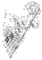
- Fig. 1 and Fig. 2 each represents a first embodiment of the present invention.
- two types of selector valves 1A and 1B having a plurality of common passages are aggregated by connecting them in lateral direction and are mounted on a rail 4.
- the rail 4 is designed with a groove-shaped cross-section. On upper ends of groove walls 4a and 4a, flange-shaped engaging edges 4b and 4b are arranged, which extend horizontally and outwardly in lateral direction of the rail 4.
- the selector valve 1A is a double-pilot type selector valve having two pilot valve units 3 and 3, while the selector valve 1B is a single-pilot type selector valve having one pilot valve unit 3.
- These selector valves 1A and 1B have different number of pilot valve units 3, and this results in some differences in the arrangement and the switching methods, but these valves are substantially the same in basic arrangement and the mounting procedure on the rail 4. Therefore, description will be given below on the double-pilot type selector valve 1A, which is represented in Fig. 2.
- the selector valve 1A comprises a main valve unit 2 for switching over compressed air and the two electromagnetically operated pilot valve units 3 and 3.
- the main valve unit 2 has a valve body 6 in form of rectangular parallelopiped.
- the valve body 6 comprises a supply passage 7 and discharge passages 8A and 8B, which are penetrating the valve body 6 in lateral direction (a direction perpendicular to the paper surface in Fig. 2) and serve as common passages as these are communicated with passages of the other selector valves 1A and 1B, output bores 9A and 9B opened on upper surface of the valve body 6, and a valve bore 10 communicated with each of the passages and the output ports.
- a spool type valve member 11 for switching over the fluid is slidably mounted.
- an adaptor 13 for connecting output pipes to the output bores 9A and 9B is fixed by means of mounting screws 14.
- the adaptor 13 is provided with two output ports 13A and 13B, independently communicated with the output bores 9A and 9B.
- output pipes are connected directly or via pipe fittings 15.
- holes 16, 17A and 17B communicated with the supply passage 7 and the discharge passages 8A and 8B are formed.
- a bottom cover 18 is mounted on the bottom surface of the valve body 6.
- the holes 16, 17A and 17B are, for examples, punching holes or fabrication holes for providing through-holes communicated with the supply passage 7 or discharge passages 8A and 8B with the valve bore 10 and are not necessarily required.
- sub-bodies 20 and 20 are mounted respectively, and pistons 22 and 22 are slidably accommodated in the piston chambers 21 and 21 formed in the sub-bodies 20 and 20.
- pilot valve units 3 and 3 On outer sides of the sub-bodies 20 and 20, the electromagnetically operated pilot valve units 3 and 3 are mounted. By turning the pilot valve units 3 and 3 alternately on and off, pilot pneumatic pressure is supplied to the piston chambers 21 and 21 to drive the pistons 22 and 22 and to switch over the valve member 11.
- reference numeral 23 represents a manual operating means, by which compressed air from the supply passage 7 is directly supplied to the piston chambers 21 and 21 by manual operation.
- the bottom cover 18 fixed on the bottom surface of the valve body 6 is an elongated planar member, which has a width approximately equal to the width of the bottom surface of the valve body 6 and has a length slightly longer the width of the rail 4.
- sealing members 26 for enclosing and sealing each of the holes 16, 17A and 17B are provided and are fixed on the valve body 6 by bolts 27.
- engaging sectors 28 to be engaged with the engaging edges 4b and 4b of the rail 4 are formed.
- the engaging sectors 28 are recessed, and an inward projection 30 to contact each of outer ends of the engaging edges 4b and 4b from below is provided at the lower end of an outer wall 29 of each recess.
- a contact sector 31 to contact upper surface of each of inner ends of the engaging edges 4b and 4b from above is provided.
- the engaging sectors 28 of the bottom cover 18 are engaged with the engaging edges 4b and 4b from edns in longitudinal direction of the rail 4.
- the selector valve can be mounted on the rail 4 via the bottom cover 18.
- the selector valve 1B is provided with one each of the pilot valve unit 3, the pistons 22 and the manual operating means 23.
- the valve member 11 can be switched over simply by supplying or discharging pilot air pressure with respect to one of the pistons 22. It is mounted on the rail 4 in the same manner as described for the selector valve 1A.
- the engaging sectors 28 are provided on the bottom cover 18, which is mounted on the bottom surface of the valve body 6 of the selector valves 1A and 1B for the purpose of covering the holes 16, 17A and 17B, and the selector valves are mounted on the rail 4 via the bottom cover 18.
- connection of the supply passage 7 and the discharge passages 8A and 8B between the adjacent selector valves can be executed by connecting fixtures 34.
- the connecting fixture 34 comprises seal rings 35 on both sides of a pipe, which is shorter than the width of the valve body 6.
- a port block 37 is mounted on the rail 4 by the same means as the engaging sectors provided on the bottom cover 18 of the selector valve or by other proper means.
- a side block 38 is provided further on outer side of the port block 37, and a fixing hardware 39 for fixing the entire system is mounted on the rail 4 by a screw 40 on outer side of the side block 38.
- the port block 37 is provided with a supply port and a discharge port, which are communicated with the supply passage 7 and the discharge passages 8A and 8B, i.e. common passages, and the supply and the discharge of the compressed air are collectively carried out via these ports.
- port block 37 is provided on each side of the selector valves 1A and 1B, which are aggregated, ends of the supply passage 7 and the discharge passages 8A and 8B are blocked at the positions of these port blocks 37. In case the port block 37 is provided only on one side, the opposite ends of the supply passage 7 and the discharge passages 8A and 8B are blocked by the side block 38.
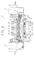
- Fig. 3 and Fig. 4 each represents a second embodiment of the present invention.
- This second embodiment is different from the above first embodiment only in that the selector valves 1A' and 1B' have only one common passage and that the fluid is discharged separately from each selector valve.
- the mounting structures of the selector valves 1A' and 1B' on the rail 4 are substantially the same as the first embodiment.
- a valve body 42 has only one supply passage 7, and compressed air is supplied concentratively through the supply passage 7.
- discharge holes 43A and 43B are formed, and discharge ports 45A and 45B are provided on a bottom cover 44 mounted on the lower surface at the positions to match the discharge holes 43A and 43B.
- Mufflers 46 and 46 made of porous materials are mounted on the discharge ports.
- valve body 6 having a plurality of common passages as used in the first embodiment When the valve body 6 having a plurality of common passages as used in the first embodiment is used and the unnecessary common passages are blocked by plugs, the same function as that of the second embodiment can be accomplished.
- plugs those designed in the same shape as the connecting fixture 34 and not hollow are preferably used.
- double-pilot type selector valves and a single pilot type selector valve are used, whereas it is needless to say that only one type of selector valve may be used.
- the selector valves are 5-port valves in all cases, while the present invention is not limited to the 5-port valve, and 3-port valve or 4-port valve may be used. Or, instead of the pilot valve, a direct-operating electromagnetic selector valve may be used. Further, a valve driven by mechanical driving means may be used.
Landscapes
- Engineering & Computer Science (AREA)
- General Engineering & Computer Science (AREA)
- Mechanical Engineering (AREA)
- Physics & Mathematics (AREA)
- Fluid Mechanics (AREA)
- Valve Housings (AREA)
- Multiple-Way Valves (AREA)
- Fluid-Driven Valves (AREA)
Claims (6)
- Assemblage de vannes montées sur rail, comprenant une pluralité de vannes de sélection (1A,1B ; 1A',1B') assemblées par liaison en direction latérale et un rail (4) pour le montage des vannes de sélection (1A,1B ; 1A',1B'), dans lequel :ledit rail (4) a une coupe transversale en forme de rainure et est muni d'une paire de bords (4b) d'accouplement en forme d'aile faisant saillie dans des directions opposées l'une à l'autre et dans la direction latérale du rail (4) sur l'extrémité supérieure des parois (4a) de la rainure ;chacune desdites vannes de sélection (1A,1B ; 1A',1B') comprend au moins un passage commun (7,8A,8B) pénétrant dans un corps de vanne (6 ; 42) dans la direction latérale et susceptible de communiquer avec un passage d'une autre vanne de sélection (1A,1B ; 1A',1B'), des orifices de sortie (9A,9B) pour liaison à des canalisations de sortie, des trous (16,17A,17B) communiquant avec les passages communs (7,8A,8B) et ouverts sur la surface de fond du corps de vanne (6 ; 42), et un couvercle de fond (18 ; 44) monté sur la surface de fond du corps de vanne (6 ; 42) pour bloquer les trous (16, 17A, 17B) ; et dans lequelledit couvercle de fond (18 ; 44) possède des secteurs d'accouplement (28) accouplés de façon amovible avec les bords d'accouplement (4b) du rail (4), et les vannes de sélection (1A,1B ; 1A',1B') sont montées sur le rail (4) via le couvercle de fond (18 ; 44) lorsque les secteurs d'accouplement (28) sont accouplés avec les bords d'accouplement (4b).
- Assemblage de vannes montées sur rail selon la revendication 1, dans lequel les bords d'accouplement (4b) du rail (4) s'étendent vers l'extérieur dans la direction latérale du rail (4) depuis les extrémités supérieures des parois (4a) de la rainure, chacune des secteurs d'accouplement (28) du couvercle de fond (18 ; 44) comprend une saillie (30) dirigée vers l'intérieur venant au contact avec chacune des extrémités extérieures des bords d'accouplement (4b) depuis le dessous et une section de contact (31) pour venir au contact de la surface supérieure de chacune des extrémités intérieures des bords d'accouplement (4b), et en accouplant les sections de contact (31) avec les bords d'accouplement depuis les extrémités dans la direction longitudinale du rail (4), le couvercle de fond (18 ; 44) est monté sur le rail (4).
- Assemblage de vannes montées sur rail selon les revendications 1 ou 2, dans lequel les passages communs (7,8A,8B) pénétrant dans le corps de vanne (6) incluent un passage d'alimentation (7) pour fournir du fluide sous pression aux vannes de sélection (1A,1B) et des passages d'évacuation (8A, 8B) pour évacuer le fluide sous pression des vannes de sélection (1A,1B).
- Assemblage de vannes montées sur rail selon les revendications 1 ou 2, dans lequel lesdits passages communs (7) pénétrant dans le corps de vanne (1A',1B') incluent uniquement un passage d'alimentation (7) pour fournir du fluide sous pression aux vannes de sélection (1A',1B'), des sorties d'évacuation pour évacuer le fluide sous pression des vannes de sélection (1A',1B') sont prévues sur la surface de fond du corps de vanne (42), en plus des trous (16) communiquant avec le passage d'alimentation, des orifices d'évacuation (43A, 43B) pour faire communiquer les sorties d'évacuation vers l'extérieur sont ouverts en des positions permettant de s'apparier avec les sorties d'évacuation (45A,45B) sur le couvercle de fond (44).
- Assemblage de vannes montées sur rail selon la revendication 4, dans lequel les orifices d'évacuation (45A, 45B) sur le couvercle de fond (44) sont munis de silencieux (46) faits d'un matériau poreux pour réduire le bruit de l'échappement.
- Assemblage de vannes montées sur rail selon les revendications 1 ou 2, dans lequel des dispositifs de liaison (34) ayant chacun des bagues d'étanchéité (35) sur les deux côtés d'un tuyau plus court que la largeur du corps de vanne (6 ; 42) sont utilisés pour relier les passages communs (7,8A,8B) entres les vannes de sélection voisines (lA,lB ; 1A',1B') et chaque moitié du dispositif de liaison (34) est accouplée dans le passage (7,8A,8B) des vannes de sélection voisines (1A,1B ; 1A',1B').
Applications Claiming Priority (3)
| Application Number | Priority Date | Filing Date | Title |
|---|---|---|---|
| JP252871/94 | 1994-09-21 | ||
| JP25287194A JP3486238B2 (ja) | 1994-09-21 | 1994-09-21 | 切換弁 |
| JP25287194 | 1994-09-21 |
Publications (2)
| Publication Number | Publication Date |
|---|---|
| EP0703391A1 EP0703391A1 (fr) | 1996-03-27 |
| EP0703391B1 true EP0703391B1 (fr) | 1999-10-13 |
Family
ID=17243331
Family Applications (1)
| Application Number | Title | Priority Date | Filing Date |
|---|---|---|---|
| EP95305971A Expired - Lifetime EP0703391B1 (fr) | 1994-09-21 | 1995-08-25 | Soupape modulaire à montage sur un rail |
Country Status (7)
| Country | Link |
|---|---|
| US (1) | US5529088A (fr) |
| EP (1) | EP0703391B1 (fr) |
| JP (1) | JP3486238B2 (fr) |
| KR (1) | KR100193033B1 (fr) |
| CN (1) | CN1071855C (fr) |
| DE (1) | DE69512736T2 (fr) |
| TW (1) | TW307333U (fr) |
Families Citing this family (88)
| Publication number | Priority date | Publication date | Assignee | Title |
|---|---|---|---|---|
| JPH0942525A (ja) * | 1995-07-26 | 1997-02-14 | Smc Corp | パイロット形切換弁 |
| USD409278S (en) * | 1996-02-09 | 1999-05-04 | Smc Corporation | Electromagnetic valve |
| USD415255S (en) * | 1996-02-09 | 1999-10-12 | Smc Corporation | Electromagnetic valve |
| USD414246S (en) | 1996-02-09 | 1999-09-21 | Smc Corporation | Electromagnetic valve |
| USD410522S (en) * | 1996-02-21 | 1999-06-01 | Smc Corporation | Electromagnetic valve |
| USD415256S (en) * | 1996-07-10 | 1999-10-12 | Smc Corporation | Electromagnetic valve assembly |
| USD409279S (en) * | 1996-07-10 | 1999-05-04 | Smc Corporation | Air supply and discharge block for an electromagnetic valve assembly |
| USD414545S (en) | 1996-07-11 | 1999-09-28 | Smc Corporation | Electromagnetic valve assembly |
| JP3850926B2 (ja) * | 1996-07-29 | 2006-11-29 | Smc株式会社 | パイロット式切換弁 |
| USD424166S (en) * | 1996-10-07 | 2000-05-02 | Smc Corporation | Electromagnetic valve assembly |
| FR2757599B1 (fr) * | 1996-12-23 | 1999-01-29 | Ksb Sa | Actionneur de robinet dans lequel la base du boitier est conformee de maniere a assurer les liaisons de distribution du fluide |
| JP3814704B2 (ja) * | 1997-05-08 | 2006-08-30 | 忠弘 大見 | 流体制御器用継手 |
| JP4045366B2 (ja) * | 1997-08-11 | 2008-02-13 | Smc株式会社 | 流体圧機器用配管継手 |
| JP4016151B2 (ja) * | 1997-08-14 | 2007-12-05 | Smc株式会社 | 5ポート電磁弁ボディを利用した2ポート電磁弁 |
| US6102068A (en) * | 1997-09-23 | 2000-08-15 | Hewlett-Packard Company | Selector valve assembly |
| US6076543A (en) * | 1997-11-06 | 2000-06-20 | United States Filter Corporation | Gas handling device |
| JPH11141715A (ja) * | 1997-11-07 | 1999-05-28 | Smc Corp | 電磁弁組立体の給電装置 |
| JP3941025B2 (ja) * | 1998-01-06 | 2007-07-04 | Smc株式会社 | レール取付形流体圧機器 |
| CN1289851C (zh) * | 1998-03-05 | 2006-12-13 | 斯瓦戈洛克公司 | 歧管系统 |
| US6629546B2 (en) * | 1998-03-05 | 2003-10-07 | Swagelok Company | Modular surface mount manifold assemblies |
| US7048007B2 (en) * | 1998-03-05 | 2006-05-23 | Swagelok Company | Modular surface mount manifold assemblies |
| US6036107A (en) * | 1998-03-31 | 2000-03-14 | Spraying System Co. | Control valve arrangement for spraying systems |
| US6189807B1 (en) * | 1998-03-31 | 2001-02-20 | Spraying Systems Co. | Valve controlled spraying system |
| USD427284S (en) * | 1998-04-13 | 2000-06-27 | Smc Corporation | Port block for valve piping |
| US6158454A (en) * | 1998-04-14 | 2000-12-12 | Insync Systems, Inc. | Sieve like structure for fluid flow through structural arrangement |
| DE29807097U1 (de) * | 1998-04-20 | 1998-09-03 | Bürkert Werke GmbH & Co., 74653 Ingelfingen | Modulares elektrofluidisches Baukastensystem |
| JPH11325291A (ja) * | 1998-05-14 | 1999-11-26 | Smc Corp | 切換弁用マニホールド |
| KR100555168B1 (ko) * | 1998-05-18 | 2006-03-03 | 더 스와겔로크 컴퍼니 | 모듈형 표면 실장 매니폴드 조립체 |
| US7036528B2 (en) | 1998-05-18 | 2006-05-02 | Swagelok Company | Modular surface mount manifold assemblies |
| US6085783A (en) * | 1998-09-02 | 2000-07-11 | Hollingshead; J. Gregory | Unified modular multi-directional flow chemical distribution block |
| WO1999064771A1 (fr) | 1998-06-12 | 1999-12-16 | Hollingshead J Gregory | Blocs modulaires unifies de distribution de produits chimiques |
| US6260581B1 (en) * | 1998-06-12 | 2001-07-17 | J. Gregory Hollingshead | Apparatus for assembling modular chemical distribution substrate blocks |
| FR2797319B1 (fr) * | 1999-08-05 | 2002-03-08 | Legris Sa | Module fluidique |
| DE10054868A1 (de) * | 2000-11-06 | 2002-05-23 | Mannesmann Rexroth Ag | Block zur Ansteuerung von Ventilbaugruppen |
| JP4628541B2 (ja) * | 2000-12-25 | 2011-02-09 | シーケーディ株式会社 | 電空レギュレータ |
| DE20106366U1 (de) | 2001-04-11 | 2001-08-09 | FESTO AG & Co., 73734 Esslingen | Wandbefestigungseinrichtung für eine Wartungseinheit |
| JP2003065453A (ja) * | 2001-08-28 | 2003-03-05 | Smc Corp | バルブ用ボディ及びその製造方法 |
| JP2004011735A (ja) * | 2002-06-06 | 2004-01-15 | Koganei Corp | 電磁弁 |
| US7178556B2 (en) * | 2003-08-07 | 2007-02-20 | Parker-Hannifin Corporation | Modular component connector substrate assembly system |
| DE10336334B3 (de) * | 2003-08-08 | 2005-08-04 | Cnh Baumaschinen Gmbh | Hydraulisches Steuersystem für Baumaschinenen, insbesondere für Bagger |
| US7021332B2 (en) * | 2004-03-26 | 2006-04-04 | Husco International, Inc. | Hydraulic valve section with reduced bore distortion |
| US7048008B2 (en) * | 2004-04-13 | 2006-05-23 | Ultra Clean Holdings, Inc. | Gas-panel assembly |
| DE102004018115B4 (de) * | 2004-04-14 | 2011-09-15 | Siemens Ag | Baugruppe mit zwei Teilkomponenten sowie Dichtungsmodul |
| JP4258812B2 (ja) * | 2004-04-22 | 2009-04-30 | Smc株式会社 | 連接形電磁弁 |
| JP4129687B2 (ja) * | 2004-04-22 | 2008-08-06 | Smc株式会社 | マニュアル釦付き電磁弁 |
| JP4258813B2 (ja) * | 2004-04-22 | 2009-04-30 | Smc株式会社 | 連接形電磁弁 |
| US20050258264A1 (en) * | 2004-05-21 | 2005-11-24 | Simensen Thomas O | Prefabricated stand for hydronic systems |
| US20060011246A1 (en) * | 2004-07-09 | 2006-01-19 | Leys John A | Fluid flow control system and method |
| US20060070674A1 (en) * | 2004-10-01 | 2006-04-06 | Eidsmore Paul G | Substrate with offset flow passage |
| KR100561529B1 (ko) * | 2005-03-24 | 2006-03-17 | 주식회사 유니크 | 솔레노이드 밸브 고정장치 |
| US7320339B2 (en) * | 2005-06-02 | 2008-01-22 | Ultra Clean Holdings, Inc. | Gas-panel assembly |
| US7299825B2 (en) * | 2005-06-02 | 2007-11-27 | Ultra Clean Holdings, Inc. | Gas-panel assembly |
| JP4919002B2 (ja) * | 2005-06-20 | 2012-04-18 | Smc株式会社 | マニホールド形電磁弁集合体 |
| US20070224708A1 (en) * | 2006-03-21 | 2007-09-27 | Sowmya Krishnan | Mass pulse sensor and process-gas system and method |
| US20080009977A1 (en) * | 2006-07-10 | 2008-01-10 | Ultra Clean Holdings | Apparatus and Method for Monitoring a Chemical-Supply System |
| US20100112814A1 (en) * | 2006-09-06 | 2010-05-06 | Sowmya Krishnan | Pre-certified process chamber and method |
| JP4750735B2 (ja) * | 2007-02-26 | 2011-08-17 | シーケーディ株式会社 | 電磁弁サブベース及び電磁弁ブロック |
| US20090078324A1 (en) * | 2007-09-21 | 2009-03-26 | Ultra Clean Technology, Inc. | Gas-panel system |
| US20090114295A1 (en) * | 2007-11-06 | 2009-05-07 | Ultra Clean Holdings, Inc. | Gas-panel assembly |
| US8307854B1 (en) | 2009-05-14 | 2012-11-13 | Vistadeltek, Inc. | Fluid delivery substrates for building removable standard fluid delivery sticks |
| WO2010144541A2 (fr) * | 2009-06-10 | 2010-12-16 | Vistadeltek, Llc | Substrats d'amenée de fluide pour débits extrêmes et / ou hautes températures |
| USD733665S1 (en) * | 2011-12-16 | 2015-07-07 | Siemens Aktiengesellschaft | Programmable logic controller (PLC) |
| US10613553B2 (en) * | 2013-07-09 | 2020-04-07 | Deka Products Limited Partnership | Modular valve apparatus and system |
| JP5938839B2 (ja) * | 2014-02-10 | 2016-06-22 | Smc株式会社 | 電磁パイロット式スプール弁 |
| JP6134285B2 (ja) * | 2014-03-27 | 2017-05-24 | 株式会社コガネイ | マニホールド電磁弁 |
| JP6165662B2 (ja) * | 2014-03-27 | 2017-07-19 | 株式会社コガネイ | マニホールド電磁弁 |
| DE202014104599U1 (de) * | 2014-09-25 | 2014-10-09 | Bürkert Werke GmbH | Modulares Ventilsystem |
| JP6976512B2 (ja) | 2015-03-27 | 2021-12-08 | プロジェクト モレー, インコーポレイテッド | カテーテルおよびその他の使用のための関節運動システム、デバイス、および方法 |
| JP6467711B2 (ja) * | 2015-06-24 | 2019-02-13 | Smc株式会社 | 多連一体型マニホールドバルブ |
| EP3349843B1 (fr) * | 2015-09-15 | 2021-06-30 | Repligen Corporation | Système de gestion de tubulure flexible pour applications pharmaceutiques, liées aux bio-procédés, et applications alimentaires/liées aux produits laitiers |
| EP3356684B1 (fr) | 2015-10-02 | 2024-11-27 | Asco, L.P. | Bloc collecteur |
| CA2996505C (fr) | 2015-10-02 | 2019-11-05 | Asco, L.P. | Boitier de collecteur et valve combine pour banc de collecteurs obtenu par un procede de fabrication additive |
| CN108601925B (zh) | 2015-12-04 | 2021-06-29 | 项目莫里股份有限公司 | 用于导管和其他用途的输入和铰接系统 |
| WO2017096362A1 (fr) | 2015-12-04 | 2017-06-08 | Barrish Mark D | Ancrages à articulation latérale pour cathéters et autres utilisations |
| CN108368947B (zh) * | 2015-12-14 | 2022-10-28 | Smc株式会社 | 电磁阀用歧管组装体及使用它的电磁阀集合体 |
| WO2017143170A1 (fr) | 2016-02-17 | 2017-08-24 | Keith Phillip Laby | Contraction locale de corps souples par dilatation de ballonnets pour articulation de cathéter par extension-contraction et autres usages |
| WO2017165810A1 (fr) | 2016-03-25 | 2017-09-28 | Phillip Laby | Systèmes, dispositifs et procédés de perfectionnement de fonctionnement d'articulation et de déplacement de gaine actionnés par fluide destinés à des cathéters, des manipulateurs de continuum et d'autres utilisations |
| US11420021B2 (en) | 2016-03-25 | 2022-08-23 | Project Moray, Inc. | Fluid-actuated displacement for catheters, continuum manipulators, and other uses |
| WO2018064398A1 (fr) | 2016-09-28 | 2018-04-05 | Project Moray, Inc. | Procédés et dispositifs de diagnostic et/ou d'administration de traitement de l'arythmie, et systèmes robotisés pour d'autres utilisations |
| US10814102B2 (en) | 2016-09-28 | 2020-10-27 | Project Moray, Inc. | Base station, charging station, and/or server for robotic catheter systems and other uses, and improved articulated devices and systems |
| BE1024953B1 (fr) * | 2017-01-31 | 2018-08-30 | Out And Out Chemistry Sprl | Méthode pour connecter au moins deux vannes fluidiques et le système de communication fluidique mis en œuvre |
| JP6819867B2 (ja) * | 2017-02-16 | 2021-01-27 | Smc株式会社 | 電磁弁用マニホールドベース及びそれを用いた電磁弁集合体 |
| DE102017106892A1 (de) * | 2017-03-30 | 2018-10-04 | Bürkert Werke GmbH & Co. KG | Ventilinsel |
| US10905861B2 (en) | 2017-04-25 | 2021-02-02 | Project Moray, Inc. | Matrix supported balloon articulation systems, devices, and methods for catheters and other uses |
| EP3822523A4 (fr) | 2018-09-07 | 2022-04-27 | SMC Corporation | Distributeur à tiroir |
| KR102543591B1 (ko) * | 2018-10-31 | 2023-06-13 | 가부시키가이샤 후지킨 | 유체 제어 장치 및 유체 제어 장치의 제조 방법 |
| CN109723893A (zh) * | 2019-02-28 | 2019-05-07 | 星宇电子(宁波)有限公司 | 一种电磁阀手动杆自锁装置 |
| DE102019212210B4 (de) * | 2019-08-14 | 2022-10-20 | Festo Se & Co. Kg | Ventilanordnung |
Family Cites Families (7)
| Publication number | Priority date | Publication date | Assignee | Title |
|---|---|---|---|---|
| US3698432A (en) * | 1970-10-08 | 1972-10-17 | Fluidic Controls Corp | Fluid logic module assembly with built-in manifold |
| US4082324A (en) * | 1976-10-04 | 1978-04-04 | Obrecht Robert E | Connection arrangement for manifold blocks |
| FR2504610A1 (fr) * | 1981-04-24 | 1982-10-29 | Telemecanique Electrique | Systeme de distribution par voie electrique de signaux de commande pneumatique |
| DE3636635A1 (de) * | 1986-10-28 | 1988-05-11 | Karl Hehl | Kuehleinrichtung an einer kunststoff-spritzgiessmaschine |
| DE3827749A1 (de) * | 1988-08-16 | 1990-02-22 | Festo Kg | Aufspannvorrichtung |
| US4917143A (en) * | 1989-09-07 | 1990-04-17 | Burton Mechanical Contractors, Inc. | Inlet vacuum valve with quick-release mounting apparatus for unit controller |
| DE4143274C2 (de) * | 1991-12-27 | 1994-03-10 | Mannesmann Ag | Ventilbaugruppe in Modulbauweise |
-
1994
- 1994-09-21 JP JP25287194A patent/JP3486238B2/ja not_active Expired - Lifetime
- 1994-12-12 TW TW085212231U patent/TW307333U/zh unknown
-
1995
- 1995-08-08 US US08/512,403 patent/US5529088A/en not_active Expired - Lifetime
- 1995-08-25 EP EP95305971A patent/EP0703391B1/fr not_active Expired - Lifetime
- 1995-08-25 DE DE69512736T patent/DE69512736T2/de not_active Expired - Lifetime
- 1995-09-20 CN CN95117304A patent/CN1071855C/zh not_active Expired - Lifetime
- 1995-09-20 KR KR1019950030860A patent/KR100193033B1/ko not_active Expired - Fee Related
Also Published As
| Publication number | Publication date |
|---|---|
| CN1123374A (zh) | 1996-05-29 |
| US5529088A (en) | 1996-06-25 |
| JPH0893941A (ja) | 1996-04-12 |
| EP0703391A1 (fr) | 1996-03-27 |
| CN1071855C (zh) | 2001-09-26 |
| JP3486238B2 (ja) | 2004-01-13 |
| DE69512736T2 (de) | 2000-03-02 |
| TW307333U (en) | 1997-06-01 |
| KR100193033B1 (ko) | 1999-06-15 |
| KR960011216A (ko) | 1996-04-20 |
| DE69512736D1 (de) | 1999-11-18 |
Similar Documents
| Publication | Publication Date | Title |
|---|---|---|
| EP0703391B1 (fr) | Soupape modulaire à montage sur un rail | |
| KR102647039B1 (ko) | 다연 일체형 매니폴드 밸브 | |
| JP4016152B2 (ja) | 切換弁組立体 | |
| EP0719949B2 (fr) | Dispositif pour vannes de commande | |
| KR100286705B1 (ko) | 전자파일럿식 3위치 전환밸브 | |
| JP4919002B2 (ja) | マニホールド形電磁弁集合体 | |
| EP3584481B1 (fr) | Base de collecteur pour électrovanne et électrovanne de type collecteur | |
| JPH06323456A (ja) | マニホールドバルブ | |
| US5845679A (en) | Pilot selector valve | |
| US20100181510A1 (en) | Selector valve device | |
| US20060086395A1 (en) | Electromagnetic pilot type directional control valve | |
| KR100216973B1 (ko) | 파일럿형 변환밸브 | |
| KR19990088247A (ko) | 전환밸브용매니폴드 | |
| US20220018341A1 (en) | Cylinder drive device and flow channel unit | |
| JP2571089Y2 (ja) | 切換弁 | |
| JP2563914Y2 (ja) | 多連切換弁 | |
| JP2605521Y2 (ja) | ダイヤフラムポンプ | |
| TW202012817A (zh) | 線軸閥 | |
| JP2506046Y2 (ja) | パイロット形電磁弁の給電装置 | |
| JPH02138504A (ja) | シリンダ内のピストンの制御装置 | |
| JPH1054473A (ja) | マニホールド | |
| JP2597407Y2 (ja) | ダブルパイロット形電磁弁 | |
| JPH0673405U (ja) | アクチュエータ | |
| JPH0554878U (ja) | パイロット形2位置切換弁 | |
| JPH07119853A (ja) | スライド弁 |
Legal Events
| Date | Code | Title | Description |
|---|---|---|---|
| PUAI | Public reference made under article 153(3) epc to a published international application that has entered the european phase |
Free format text: ORIGINAL CODE: 0009012 |
|
| 17P | Request for examination filed |
Effective date: 19950905 |
|
| AK | Designated contracting states |
Kind code of ref document: A1 Designated state(s): DE FR GB IT |
|
| 17Q | First examination report despatched |
Effective date: 19980612 |
|
| GRAG | Despatch of communication of intention to grant |
Free format text: ORIGINAL CODE: EPIDOS AGRA |
|
| GRAG | Despatch of communication of intention to grant |
Free format text: ORIGINAL CODE: EPIDOS AGRA |
|
| GRAH | Despatch of communication of intention to grant a patent |
Free format text: ORIGINAL CODE: EPIDOS IGRA |
|
| GRAH | Despatch of communication of intention to grant a patent |
Free format text: ORIGINAL CODE: EPIDOS IGRA |
|
| GRAA | (expected) grant |
Free format text: ORIGINAL CODE: 0009210 |
|
| AK | Designated contracting states |
Kind code of ref document: B1 Designated state(s): DE FR GB IT |
|
| ITF | It: translation for a ep patent filed | ||
| REF | Corresponds to: |
Ref document number: 69512736 Country of ref document: DE Date of ref document: 19991118 |
|
| ET | Fr: translation filed | ||
| PLBE | No opposition filed within time limit |
Free format text: ORIGINAL CODE: 0009261 |
|
| STAA | Information on the status of an ep patent application or granted ep patent |
Free format text: STATUS: NO OPPOSITION FILED WITHIN TIME LIMIT |
|
| 26N | No opposition filed | ||
| PGFP | Annual fee paid to national office [announced via postgrant information from national office to epo] |
Ref country code: FR Payment date: 20010810 Year of fee payment: 7 |
|
| PGFP | Annual fee paid to national office [announced via postgrant information from national office to epo] |
Ref country code: GB Payment date: 20010822 Year of fee payment: 7 |
|
| REG | Reference to a national code |
Ref country code: GB Ref legal event code: IF02 |
|
| PG25 | Lapsed in a contracting state [announced via postgrant information from national office to epo] |
Ref country code: GB Free format text: LAPSE BECAUSE OF NON-PAYMENT OF DUE FEES Effective date: 20020825 |
|
| GBPC | Gb: european patent ceased through non-payment of renewal fee |
Effective date: 20020825 |
|
| PG25 | Lapsed in a contracting state [announced via postgrant information from national office to epo] |
Ref country code: FR Free format text: LAPSE BECAUSE OF NON-PAYMENT OF DUE FEES Effective date: 20030430 |
|
| REG | Reference to a national code |
Ref country code: FR Ref legal event code: ST |
|
| PG25 | Lapsed in a contracting state [announced via postgrant information from national office to epo] |
Ref country code: IT Free format text: LAPSE BECAUSE OF NON-PAYMENT OF DUE FEES Effective date: 20050825 |
|
| PGFP | Annual fee paid to national office [announced via postgrant information from national office to epo] |
Ref country code: DE Payment date: 20140821 Year of fee payment: 20 |
|
| REG | Reference to a national code |
Ref country code: DE Ref legal event code: R071 Ref document number: 69512736 Country of ref document: DE |