EP0703444A1 - Vorrichtung und Verfahren zur Infrarotgasanalyse - Google Patents
Vorrichtung und Verfahren zur Infrarotgasanalyse Download PDFInfo
- Publication number
- EP0703444A1 EP0703444A1 EP95306504A EP95306504A EP0703444A1 EP 0703444 A1 EP0703444 A1 EP 0703444A1 EP 95306504 A EP95306504 A EP 95306504A EP 95306504 A EP95306504 A EP 95306504A EP 0703444 A1 EP0703444 A1 EP 0703444A1
- Authority
- EP
- European Patent Office
- Prior art keywords
- gas
- infrared
- path
- sample cell
- energy
- Prior art date
- Legal status (The legal status is an assumption and is not a legal conclusion. Google has not performed a legal analysis and makes no representation as to the accuracy of the status listed.)
- Withdrawn
Links
- 238000000034 method Methods 0.000 title claims abstract description 21
- 239000007789 gas Substances 0.000 claims abstract description 144
- 230000003287 optical effect Effects 0.000 claims abstract description 46
- 238000001228 spectrum Methods 0.000 claims description 26
- 239000000203 mixture Substances 0.000 claims description 14
- 238000000862 absorption spectrum Methods 0.000 claims description 9
- 238000012545 processing Methods 0.000 claims description 7
- 238000010521 absorption reaction Methods 0.000 abstract description 44
- CURLTUGMZLYLDI-UHFFFAOYSA-N Carbon dioxide Chemical compound O=C=O CURLTUGMZLYLDI-UHFFFAOYSA-N 0.000 description 42
- 229910002092 carbon dioxide Inorganic materials 0.000 description 23
- GQPLMRYTRLFLPF-UHFFFAOYSA-N Nitrous Oxide Chemical compound [O-][N+]#N GQPLMRYTRLFLPF-UHFFFAOYSA-N 0.000 description 18
- 229960003132 halothane Drugs 0.000 description 13
- BCQZXOMGPXTTIC-UHFFFAOYSA-N halothane Chemical compound FC(F)(F)C(Cl)Br BCQZXOMGPXTTIC-UHFFFAOYSA-N 0.000 description 13
- PIWKPBJCKXDKJR-UHFFFAOYSA-N Isoflurane Chemical compound FC(F)OC(Cl)C(F)(F)F PIWKPBJCKXDKJR-UHFFFAOYSA-N 0.000 description 12
- 229960000305 enflurane Drugs 0.000 description 12
- JPGQOUSTVILISH-UHFFFAOYSA-N enflurane Chemical compound FC(F)OC(F)(F)C(F)Cl JPGQOUSTVILISH-UHFFFAOYSA-N 0.000 description 12
- 229960002725 isoflurane Drugs 0.000 description 12
- 230000035945 sensitivity Effects 0.000 description 12
- 229960002078 sevoflurane Drugs 0.000 description 12
- DFEYYRMXOJXZRJ-UHFFFAOYSA-N sevoflurane Chemical compound FCOC(C(F)(F)F)C(F)(F)F DFEYYRMXOJXZRJ-UHFFFAOYSA-N 0.000 description 12
- 238000001914 filtration Methods 0.000 description 10
- 229910052734 helium Inorganic materials 0.000 description 9
- 238000004458 analytical method Methods 0.000 description 7
- 239000003193 general anesthetic agent Substances 0.000 description 5
- 239000001307 helium Substances 0.000 description 5
- SWQJXJOGLNCZEY-UHFFFAOYSA-N helium atom Chemical compound [He] SWQJXJOGLNCZEY-UHFFFAOYSA-N 0.000 description 5
- 238000004891 communication Methods 0.000 description 4
- 230000003247 decreasing effect Effects 0.000 description 4
- 238000004868 gas analysis Methods 0.000 description 4
- 239000003994 anesthetic gas Substances 0.000 description 3
- 239000003795 chemical substances by application Substances 0.000 description 3
- 230000000694 effects Effects 0.000 description 3
- 230000007613 environmental effect Effects 0.000 description 3
- 238000002474 experimental method Methods 0.000 description 3
- 238000005259 measurement Methods 0.000 description 3
- 230000032683 aging Effects 0.000 description 2
- 239000001569 carbon dioxide Substances 0.000 description 2
- 238000010276 construction Methods 0.000 description 2
- 239000001272 nitrous oxide Substances 0.000 description 2
- 229940124326 anaesthetic agent Drugs 0.000 description 1
- 238000001816 cooling Methods 0.000 description 1
- 230000001419 dependent effect Effects 0.000 description 1
- 238000010438 heat treatment Methods 0.000 description 1
- 238000002329 infrared spectrum Methods 0.000 description 1
- 239000011159 matrix material Substances 0.000 description 1
- 230000005855 radiation Effects 0.000 description 1
- 238000001179 sorption measurement Methods 0.000 description 1
- 230000003595 spectral effect Effects 0.000 description 1
- 238000002834 transmittance Methods 0.000 description 1
Images

Classifications
-
- G—PHYSICS
- G01—MEASURING; TESTING
- G01N—INVESTIGATING OR ANALYSING MATERIALS BY DETERMINING THEIR CHEMICAL OR PHYSICAL PROPERTIES
- G01N21/00—Investigating or analysing materials by the use of optical means, i.e. using sub-millimetre waves, infrared, visible or ultraviolet light
- G01N21/17—Systems in which incident light is modified in accordance with the properties of the material investigated
- G01N21/25—Colour; Spectral properties, i.e. comparison of effect of material on the light at two or more different wavelengths or wavelength bands
- G01N21/31—Investigating relative effect of material at wavelengths characteristic of specific elements or molecules, e.g. atomic absorption spectrometry
- G01N21/35—Investigating relative effect of material at wavelengths characteristic of specific elements or molecules, e.g. atomic absorption spectrometry using infrared light
- G01N21/3504—Investigating relative effect of material at wavelengths characteristic of specific elements or molecules, e.g. atomic absorption spectrometry using infrared light for analysing gases, e.g. multi-gas analysis
Definitions
- the invention relates to infrared gas analyzers.
- the infrared energy passes through the sample in a sample cell and is detected by an infrared sensor.
- the infrared energy will be reduced by the presence of any gas that absorbs infrared energy.
- the wavelength band of the beam of infrared energy passing through the sample cell containing the gas sample is changed periodically by the selective interposition of one or more filters in the path of the beam.
- the filters are usually carried on a rotatable wheel.
- each filter passes only radiation at a narrow band corresponding to a characteristic absorption wavelength band of a particular gas of interest. Therefore, through use of an infrared filter that is selected for each gas to be monitored in the gas sample, only infrared energy that can be absorbed by that gas is allowed to pass through the filter and be detected by the sensor.
- the changes in infrared energy detected may be caused by the infrared source itself changing its power output.
- the power output of the infrared source can change as the gas analyzer as a whole heats up and as the power source ages. To ensure accuracy in gas analysis, these types of changes in the infrared source power output have to be handled in some particular manner.
- one particular method of determining infrared source output is to use a second or additional filter to look at a wavelength in the infrared spectrum that is not changed by the gas to be monitored or any other gas that could be in the sample cell when the gas analyzer unit is in normal use.
- This method may not produce the best results for the following reasons. As the infrared source ages, the power output spectra changes. Therefore, wavelength where gas absorption is being checked may change in one direction and the wavelength where power level changes may change in the other direction.
- served heaters minimizes changes within the infrared analyzer, however, significantly increased cost, power consumption and heat buildup makes served heaters not a preferred method for minimizing changes in power output of the infrared source.
- the invention provides a method for analyzing a gas mixture for gases of interest comprising the steps:
- the invention also provides a gas analyzer comprising: an infrared energy source; a sensor for detecting infrared energy from said source, said infrared energy traveling between said source and said sensor on an optical path; a sample cell in said optical path containing a gas mixture to be analyzed; at least two reference cells supported for selective positioning in said optical path, an infrared filter in said optical path; said sensor producing a signal representative of the energy remaining when each of said reference cells are in said optical path; and signal processing means connected to said sensor for producing an output indicative of the concentration of at least one predetermined gas in said sample cell.
- the analyzer and method for analyzing gases in accordance with the invention employs one optical path which includes one infrared source, one sample cell containing the gas(es) to be analyzed, one infrared sensor and one infrared filter no matter how many gases are to be analyzed.
- the one optical path with one filter is utilized for both determining infrared source output and infrared absorption by the gas(es) to be measured.
- the filter is preferably a wideband bandpass filter that is selected to pass the necessary gas spectra points of the gas(es) to be analyzed as well as two spectra sidebands which are the additional spectra on each side of the gas spectra points.
- the gas spectra points of interest will not be lost when the filter shifts in the spectra due to changes in the environmental temperature or age. Further, the two sidebands are utilized as a non-changing infrared power level indicator.
- reference cells containing known quantities of particular gases are used as negative filters.
- the reference cells are mounted to be selectively interposed in the optical path one reference cell at a time.
- the infrared sensor takes a number of readings of the energy reaching the sensor, i.e. a reading as each reference cell is interposed in the optical path.
- the information obtained from the multiple readings is analyzed to determine the presence and/or amount of gases being monitored.
- a microprocessor analyzes the energy readings from the sensor and determines the concentration of gases that are in the sample cell.
- the invention thus provides a relatively simple and accurate gas analyzer and method that can accurately handle changes in the infrared source power output and/or changes in temperature within the analyzer, and can also accurately handle filter spectra shift.
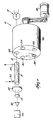
- FIG. 1 there is shown an infrared gas analyzer 10 embodying the invention.
- the analyzer 10 will be described in relation to the analysis of four anesthetic agents; halothane, enflurane, isoflurane, and sevoflurane.
- the analyzer 10 of the present invention may be used to analyze other combinations of gases.
- the analyzer 10 includes an infrared source 12 such as 5v flashlight bulb.
- an infrared sensor 14 such as the infrared detector manufactured by Graseby of Orlando, Florida as part number 1500115.
- the path of infrared light between the infrared source 12 and the infrared sensor 14 defines an optical path 16.
- a sample cell 18 Disposed in the optical path 16 is a sample cell 18 that contains the gas mixture to be analyzed.
- the gas mixture to be analyzed is the breath of an anesthetized subject.
- the sample cell 18 has a gas inlet 20 which enables the gas mixture to enter the sample cell 18 and a gas outlet 22 which enables the gas mixture to exit the sample cell 18.
- the dimensions of the sample cell 18 are chosen so as to optimize both response time and sensitivity of analyzer 10. Sensitivity and response time are effected by the length of a sample cell. That is, a sample cell which is too long results in increased sensitivity however with decreased response time and a sample cell which is too short results in increased response time however with decreased sensitivity.
- the dimensions of a sample cell are thus chosen with proper consideration for response time and sensitivity and are selected between what would be the lengths that would provide either the best response time or the best sensitivity, i.e. that length which affords the best of both.
- the four anesthetic agents halothane, enflurane, isoflurane and sevoflurane have poor absorption characteristics and thus require a longer sample cell.
- the sample cell 18 which may contain the above-identified four anesthetic agents preferably has the following dimensions: 0.249'' x 2.02'' (6.325mm x 51.31mm).
- infrared filter 24 Further disposed in the optical path 16 is a single infrared filter 24. To ensure accuracy in gas analysis, changes in the infrared source power output are handled by analyzer 10 through use of the filter 24. Filter 24 is thus utilized for determining both infrared source output and infrared absorption by the gases to be measured. The use of only one filter 24 leads to more accurate gas measurements because the same optical path 16 is used to determine both infrared source energy and adsorption.
- filter 24 is a bandpass filter that is selected so as to pass a wider band of energies than just the absorption spectra of the gases analyzer 10 is designed to analyze.
- a single wideband filter 24 passes the necessary gas spectra points which cannot be lost even if filter 24 shifts in the spectra due to changes in the environmental temperature or changes due to age of the power source.
- filter 24 is selected to pass two sidebands, i.e., additional spectra on each side of the gas spectra points of interest. The two sidebands are utilized as a non-changing infrared power level indicator. If filter 24 shifts in the spectra it is designed to pass, the sideband energy remains the same.
- filter 24 is selected to pass the expected absorption spectra of the gases to be analyzed.
- the filter is selected to pass additional spectra on each side of the gap absorption spectra, i.e., sidebands.
- the width of the sidebands passed by filter 24 is determined on the basis of expected filter and/or power output variances and the magnitude thereof and the width is such as to accommodate normal, expected operational conditions. Therefore, should the analyzer temperature or power source output vary, the variances are accommodated in the sidebands and does not effect the operation and accuracy of analyzer 10.
- these gases absorb infrared energy in the range of 3.2 - 3.4 microns.
- the filter 24 is thus chosen to pass the energy in the range of 3.16 - 3.5 microns which includes the gas spectra points of interest and two sidebands.
- analyzer 10 By using one filter 24 in analyzer 10, it is possible for analyzer 10 to be constructed with one infrared source 12 and one sample cell 18 in the optical path 16. With this construction, there can be no difference in the infrared sensor 14 output for use as a gas absorption indicator that will not also affect the sensor 14 output for use as a reference of infrared source power. Accordingly, in order to determine changes in gas concentrations with one filter 24, reference cells filled with known quantities of the particular gases to be measured are used for negative filtering which will be explained in greater depth hereafter. The number of reference cells needed is dependent upon the number of gases to be analyzed by the analyzer.
- the reference cells that are devoted to a specific gas are filled with a known quantity of that gas.
- such reference cells are mounted on a rotatable element such that only one reference cell at a time is disposed in the optical path 16.
- a rotating cylinder 26 is disposed in the optical path 16.
- the rotatable cylinder 26 is connected to a conventional motor 28 so as to effectuate the rotation of the cylinder 26.
- the cylinder 26 has therein five bores 30, 32, 34, 36 and 38 that are equidistantly spaced from one another. Bores 30, 32, 34, 36, and 38 are adapted to removeably house a reference cell. As the cylinder 26 is rotated by motor 28, the housed reference cells are sequentially disposed in the optical path 16 one at a time.
- the bores 30, 32, 34, 36 and 38 contain reference cells.
- the analyzer 10 of Fig. 1 operates as follows with reference to the example using the four anesthetic gases halothane, enflurane, isoflurane and sevoflurane.
- the reference cells A, H, E, F and S are filled with the quantities of the gases shown previously.
- the sample cell 18 is filled with the gas mixture to be analyzed via inlet 20.
- the cylinder 26 is then rotated by the motor 28 so as to sequentially dispose reference cells A, H, E, F and S in the optical path 16 one at a time.
- the infrared sensor 14 is electrically connected to a pre-amplifier 40 which itself is electrically connected to a 32 bit microprocessor 42.
- the sensor readings are thus amplified by pre-amplifier 40 then sent to microprocessor 42 to compute the gas concentrations for the various gases.
- Gas concentrations are determined through use of negative filtering. Negative filtering is where one filters out the spectra being used and keeps the part of the spectra that is not absorbed by the gas to be measured.
- the negative filtering reading when subtracted from the sensor reading without the negative filtering will give the total inband infrared energy after absorption. In other words, a reading is taken through the sample cell without any filtering. A second reading is taken but based on all of the gases present with the exception of that for which a quantitative reading is desired. A comparison of those two readings gives a measure of the amount of the gas for which the reading is desired.
- the gas concentration figures are determined mathematically via predetermined equations.
- the reading E A (which corresponds to only the gases in the sample cell absorbing energy) is used with the reading E H (which corresponds to the both the gas in reference cell H and gases in the sample cell absorbing energy).
- the mathematical equations used to determine the concentrations of each of the four agents in the example are as follows:
- the analyzer 10 of the present invention which employs one infrared filter 24 for sensing both infrared power output and gas absorption, is thus not sensitive to temperature and able to operate after a cold start-up without a delay for warm-up.
- the analyzer 10 can also operate at any infrared power level output of the infrared source 12 since it does not matter whether through aging or temperature the power output of the infrared source 12 shifts either up or down the spectra. Further, since no heating or cooling units are needed to maintain a consistent temperature, the analyzer 10 utilizes less power and can be very small in size and light weight.
- a gas analyzer unit 60 employing the present invention which is actually three independent analyzers 62, 64 and 66 in the same unit 60.
- Each of the independent analyzers 62, 64 and 66 operates analogously to the analyzer 10 of Fig. 1 and each defines one optical path having a single infrared source, a single sample cell, a single filter and a single infrared detector.
- each analyzer 62, 64 and 66 analyzes a different gas(es).
- the three analyzers 62, 64 and 66 share only common reference cells and data processing components.
- the three analyzers 62, 64 and 66 of the unit 60 can analyze any gases, however, the unit 60 depicted in Fig. 2 analyzes the following gases.
- the first analyzers 62 analyses carbon dioxide.
- the second analyzer 64 analyses nitrous oxide.
- the third analyzer 66 is substantially identical to the analyzer 10 of Fig. 1 in that it is designed to analyze the following four anesthetic gases; halothane, enflurane, isoflurane and sevoflurane.
- the structure of the unit 60 is as follows with reference to Fig. 2.
- the unit 60 has a first housing 68 with a removable cover 70.
- the housing 68 has an end wall 72 having a central aperture 74. On each side of the aperture 74 is a slot 76 and 78 that terminates in an aperture 80 and 82 respectively.
- the housing 68 has another end wall 84 having a central aperture 86 that is axially aligned with the aperture 74 of the end wall 72.
- the end wall 84 also has therein three apertures 88, 90 and 92 surrounding the central aperture 86. Apertures 88 and 92 are coaxially aligned with apertures 80 and 82 respectively on the end wall 72.
- Side walls 94 and 96 connect the end walls 72 and 84 of the housing 68.
- each side wall 94 and 96 respectively extends beyond the end wall 84 and are connected via a top wall 102.
- the side walls 94 and 96 and the end walls 72 and 84 define a recess 104 and the portions of the side wall 98 and 100, the end wall 84 and the top wall 102 define a recess 106.
- a motor 108 is housed in the recess 106.
- the motor 108 has a bracket 110 on one end.
- a mounting plate 112 is used to secure the motor 108 to the end wall 84 in that the motor 108 is secured to the plate 112 with screws 114 and the plate 112 is secured to the end wall 84 of the housing 68 with screws 116.
- the mounting plate 112 has a central aperture 118 through which extends the bracket 110 of the motor 108.
- the aperture 118 is coaxially aligned with the aperture 86 in the end wall 84.
- Also attached to the end wall 84 is a second plate 120.
- the plate 120 has therein a central aperture 122 that is coaxially aligned with the aperture 118 in the plate 112 and the aperture 86 in the end wall 84.
- the plate 120 has thereon three infrared sources 124, 126 and 128 such as 5v flashlight bulbs.
- the three infrared sources 124, 126 and 128 are spaced on the plate 120 such that when the plate 120 is secure to the end wall 84 with screws 130, the three infrared sources 124, 126 and 128 align with and extend through the apertures 88, 90 and 92 respectively in the end wall 84 and partially into the recess 104.
- a rotatable cylinder 132 is housed in recess 104.
- the cylinder 132 has therein five bores 134, 136, 138, 140 and 142 equidistantly spaced.
- Each bore 134, 136, 138, 140 and 142 is adapted to removeably house a reference cell 143 filled with a known quantity of a certain gas.
- the cylinder 132 also has therein a central bore 144 which is axially aligned with the aperture 86 in the end wall 84 and the aperture 118 in the mounting plate 112.
- the removable cover 70 enables access to the rotating cylinder 132 and the reference cells 143.
- the motor 108 is connected to the cylinder 132 to enable the cylinder 132 to rotate within the recess 104 as follows.
- a barrel 146 is positioned in the central bore 144 of the cylinder 132.
- the barrel 146 has therein a central bore 148.
- a rod 150 connects the motor 108 and the cylinder 132.
- One end of the rod 150 connects to the bracket 110 on the motor 108.
- the rod 150 extends through aperture 118 in plate 112, through aperture 122 in the plate 120, through aperture 86 in the end wall 84, through aperture 148 in the barrel 146, and is secured at the other end with a nut 152.
- the motor 108 rotates the rod 150 which in turn rotates the cylinder 132 in the recess 104.
- the unit 60 also includes a second housing 154.
- the second housing 154 is secured to the first housing 68 via screws 156.
- the second housing 154 includes a gas inlet 158.
- In communication with the gas inlet 158 is a sample cell 160.
- Sample cell 162 is in communication with the sample cell 160 via a conduit (not shown).
- Sample cell 166 is in communication with sample cell 162 via a conduit (not shown).
- a gas outlet (not shown) is in communication with the sample cell 166 and enables gas to exit from the second housing 154.
- the gas to be monitored enters the unit 60 at the inlet 158, travels through the sample cells 160, via a conduit to sample cell 162, via a conduit to sample cell 166 then exits the unit 60 via the outlet.
- a single filter 172, 174 and 176 At the end of the sample cells 160, 162 and 166 is a single filter 172, 174 and 176 respectively.
- the one filter per analyzer is utilized for the same purpose as analyzer 10 of Fig. 1 that being for determining both infrared source output and infrared absorption by the gas(es) to be measured.
- the use of only one filter per analyzer leads to more accurate gas measurements for each analyzer because the same optical path is used to determine both infrared source energy and energy absorption.
- Each filter 172, 174 and 176 is chosen to be a bandpass filter that passes a wideband of energies. Such a single wideband filter passes the necessary gas spectra points which will not be lost even when the filter shifts in the spectra due to changes in the environmental temperature or changes due to age of the power source. Further, such a wideband filter is selected to pass two sidebands which are additional spectra on each side of the gas spectra points of interest. The two sidebands are utilized as a non-changing infrared power level indicator.
- the unit 60 further includes an infrared sensor 178, 180 and 182 per analyzer 62, 64 and 66 respectively.
- the filters 172, 174 and 176 are cap-type filters which are attached to the sensor 178, 180 and 182 respectively and can be of the type manufactured by OCLI.
- the infrared sensors 178, 180 and 182 can be of the type manufactured by Graseby of Orlando, Florida as part number 1500115.
- the sensors 178, 180 and 182 are electrically connected to a preamplifier 184 which outputs the three analyzers analog sensor readings to a 32 bit microprocessor 188 for computation of gas concentrations as will be discussed in more detail hereafter.
- the unit 60 contains three optical paths which correspond to the three analyzers 62, 64 and 66.
- the first analyzer 62 contains the following optical path: the infrared source 126, the rotating cylinder 132, the sample cell 160, the filter 172 and the infrared sensor 178.
- the second analyzer 64 contains the following optical path: the infrared source 128, the rotating cylinder 132, the sample cell 162, the filter 174 and the infrared sensor 180.
- the third analyzer 66 contains the following optical path: the infrared source 124, the rotating cylinder 132, the sample cell 166, the filter 176 and the infrared sensor 182.
- the first analyzer 62 of the unit 60 is dedicated to the analysis of carbon dioxide (hereafter CO2). Due to the wave fronts of the gases entering the unit 60, in this embodiment, it is desirable that the first analyzer 62 be dedicated to the analysis of CO2.
- the dimensions of the sample cell 160 of the first analyzer 62 are also are chosen so as to optimize both response time and sensitivity. A sample cell which is too long results in increased sensitivity however with decreased response time. A sample cell which is too short results in increased response time however with decreased sensitivity. The dimensions of the sample cell are thus chosen with proper consideration for response time and sensitivity and are selected between what would be the length that would provide wither the best response time or the best sensitivity.
- the preferred dimensions of the sample cell 160 of the first analyzer 62 are as follows: 0.150'' x 0.225''.
- CO2 absorbs infrared energy in the range of between 4.2 - 4.36 microns.
- the filter 172 for the first analyzer 62 is chosen so as to include the absorption band of CO2 as well as the two sidebands previously discussed and thus allows energy between 4.0 and 4.4 microns to pass through the filter 172 and be detected by the sensor 178.
- the second analyzer 64 of the unit 60 shown in Fig. 2 is dedicated to the analysis of nitrous oxide (hereafter N2O).
- the dimensions of the sample cell 162 are chosen on the same basis as the first analyzer 62 so as to optimize response time and sensitivity and preferably are as follows: 0.150'' x 0.128''.
- N2O absorbs infrared energy in the range of between 4.44 - 4.6 microns.
- the filter 174 for the second analyzer 64 is thus chosen to allow any energy between 4.4 and 4.8 microns to pass through the filter 174 and be detected by the sensor 180.
- the third analyzer 66 of the unit 60 is substantially identical to the analyzer 10 of Fig. 1 in that it is dedicated to the analysis of the four anesthetic agents halothane, enflurane, isoflurane and sevoflurane.
- the dimensions of the sample cell 166 are identical to the dimensions of sample cell 18, and the chosen filter 176 is identical to the filter 24 earlier described.
- each analyzer 62, 64 and 66 of unit 60 employs one infrared source and one sample cell in one optical path so that there can be no difference in the sensor output for use as a reference of infrared source power output that with the sensor output for use as a gas absorption indicator.
- the rotating reference cells with known quantities of particular gases therein are used for negative filtering the same way as the analyzer 10 of Fig. 1 uses negative filtering.
- the negative filtering reading when compared with the sensor reading without the negative filtering will give the total inband infrared energy after absorption which can then be expressed as a percentage of total inband power.
- the three analyzers 62, 64 and 66 of the unit 60 shown in Fig. 2 share the rotating reference cells 143 in the cylinder 132 to minimize the size of unit 60.
- each analyzer 62, 64 and 66 could have its own set of reference cells.
- the cylinder 132 rotates within the recess 104 such that, at one time, only one reference cell 143 is aligned with any one of the optical paths of the three analyzers 62, 64 and 66.
- the three analyzers 62, 64 and 66 function sequentially in that the optical path of the three analyzers 62, 64 and 66 is offset so that only one analyzer at a time has energy from its respective infrared source pass through a reference cell, sample cell filter then be detected by the infrared sensor of that analyzer.
- the five reference cells 143 denoted herein as A, H, E, F and S contained in the rotating cylinder 132 contain known quantities of the gas(es) to be analyzed.
- the reference cells A, H, E, F and S contain the following type and amount of gases at a pressure of 760 mm Hg: Helium is included in reference cells H, E, F and S to determine leak rate. Helium does not effect the operation of the analyzer 10 for it does not absorb infrared energy.
- the three analyzers 62, 64 and 66 are able to share a common set of reference cells A, H, E, F and S because the known quantity of CO2 necessary for the operation of the first analyzer 62 can be in the same reference cell with the gases necessary for the operation of the second and third analyzers 64 and 66 and so forth because of the different frequencies of absorption of the gases to be analyzed of the three analyzers 62, 64 and 66.
- One rotation of the cylinder 132 containing the five reference cells A, H, E, F and S results in five readings from the sensor 178 of the first analyzer 62, five readings from the sensor 180 of the second analyzer 64 and five readings from the sensor 182 of the third analyzer 66.
- the operation of the three analyzers 62, 64 and 66 of the unit 60 and the method to analyze the gases are as follows.
- the operation of third analyzer 66 is the same as with Fig. 1 and will not be repeated here. Due to the similarity of the operation and method of the first and second analyzers 62 and 64 which analyze only one gas, only the operation of the first analyzer 62 will be detailed.
- the first analyzer 62 obtains five readings from the infrared sensor 178 as follows: E A , E H , E E , E F , E S .
- the reading E A is the energy incident upon the sensor 178 when reference cell A is in the optical path of the first analyzer 62. With this reading, only the CO2 present in the sample cell 160 is absorbing any energy from the infrared source 126.
- the readings E H and E S are not utilized because CO2 was not present in reference cells H or S.
- E E and E F are the energies incident upon the sensor 178 when reference cells E and F respectively are in the optical path.
- equal amounts of CO2 are present in reference cells E and F therefore the readings E E and E F should be the same thus creating a redundancy in analyzer 62. Redundant readings E E and E F will hereafter be preferred to as E E/F . If these redundant readings do not agree, this is an indication that the analyzer 62 is malfunctioning. It should be noted that it is only necessary to have a quantity of CO2 in one of the reference cells. Further, if increased redundancy is desired, the same amount of CO2 could be present in all four reference cells H, E, F and S.
- the concentration of N2O can be calculated using the five energy readings from the sensor 180 of the second analyzer 64 and the appropriate constants substituted in the above equation.
- the readings from sensor 180 can have the same redundancy as with the first analyzer 62 assuming the same quantity of N2O is present in various reference cells. In the preferred embodiment, equal amounts of N2O are present in reference cells H and E.
Landscapes
- Physics & Mathematics (AREA)
- Spectroscopy & Molecular Physics (AREA)
- Health & Medical Sciences (AREA)
- Life Sciences & Earth Sciences (AREA)
- Chemical & Material Sciences (AREA)
- Analytical Chemistry (AREA)
- Biochemistry (AREA)
- General Health & Medical Sciences (AREA)
- General Physics & Mathematics (AREA)
- Immunology (AREA)
- Pathology (AREA)
- Investigating Or Analysing Materials By Optical Means (AREA)
- Spectrometry And Color Measurement (AREA)
- Photometry And Measurement Of Optical Pulse Characteristics (AREA)
Applications Claiming Priority (2)
| Application Number | Priority Date | Filing Date | Title |
|---|---|---|---|
| US312114 | 1994-09-26 | ||
| US08/312,114 US5585635A (en) | 1994-09-26 | 1994-09-26 | Infrared gas analyzer and method |
Publications (1)
| Publication Number | Publication Date |
|---|---|
| EP0703444A1 true EP0703444A1 (de) | 1996-03-27 |
Family
ID=23209938
Family Applications (1)
| Application Number | Title | Priority Date | Filing Date |
|---|---|---|---|
| EP95306504A Withdrawn EP0703444A1 (de) | 1994-09-26 | 1995-09-14 | Vorrichtung und Verfahren zur Infrarotgasanalyse |
Country Status (4)
| Country | Link |
|---|---|
| US (1) | US5585635A (de) |
| EP (1) | EP0703444A1 (de) |
| JP (1) | JPH08105833A (de) |
| TW (1) | TW314594B (de) |
Cited By (3)
| Publication number | Priority date | Publication date | Assignee | Title |
|---|---|---|---|---|
| GB2314411A (en) * | 1996-06-21 | 1997-12-24 | Graviner Ltd Kidde | Filter wheel for use in a gas filter correlation system |
| WO2011050841A1 (en) * | 2009-10-28 | 2011-05-05 | Opsis Ab | Device for radiation absorption measurements and method for calibration thereof |
| EP3165904A4 (de) * | 2014-07-03 | 2018-01-03 | Murata Manufacturing Co., Ltd. | Gaskonzentrationsmessvorrichtung |
Families Citing this family (17)
| Publication number | Priority date | Publication date | Assignee | Title |
|---|---|---|---|---|
| US5818049A (en) * | 1997-08-29 | 1998-10-06 | Ohmeda Inc. | Infrared gas spectrometer having a lid assembly with an integrated chopper and chopper motor |
| US5925831A (en) | 1997-10-18 | 1999-07-20 | Cardiopulmonary Technologies, Inc. | Respiratory air flow sensor |
| FR2772127B1 (fr) * | 1997-12-05 | 2000-02-18 | Oldham France Sa | Procede de determination de la concentration d'un gaz dans un melange gazeux et dispositif d'analyse pour la mise en oeuvre d'un tel procede |
| US6627873B2 (en) | 1998-04-23 | 2003-09-30 | Baker Hughes Incorporated | Down hole gas analyzer method and apparatus |
| US6396056B1 (en) * | 1999-07-08 | 2002-05-28 | Air Instruments And Measurements, Inc. | Gas detectors and gas analyzers utilizing spectral absorption |
| US6359278B1 (en) | 1999-12-29 | 2002-03-19 | Ge Marquette Medical Systems, Inc. | Optical stabilization of temperature effects on an infrared gas analyzer |
| US7301148B2 (en) | 2003-04-23 | 2007-11-27 | Battelle Memorial Institute | Methods and systems for remote detection of gases |
| US7034304B2 (en) * | 2003-07-25 | 2006-04-25 | Honeywell International, Inc. | Chamber for gas detector |
| EP1850112B1 (de) * | 2005-02-14 | 2012-08-08 | Japan Science and Technology Agency | Vorrichtung zur Gaskonzentrationsmessung nach dem Gaskorrelationsverfahren |
| CN1877304B (zh) * | 2005-06-10 | 2010-04-28 | 深圳迈瑞生物医疗电子股份有限公司 | 单种麻醉气体类型编码识别的方法和装置 |
| US7782462B2 (en) * | 2006-11-27 | 2010-08-24 | Applied Nanotech Holdings, Inc. | Sono-photonic gas sensor |
| US7679046B1 (en) * | 2007-10-08 | 2010-03-16 | Flir Systems, Inc. | Infrared camera calibration systems and methods |
| KR101014245B1 (ko) * | 2008-11-11 | 2011-02-16 | 한국표준과학연구원 | 멀티가스필터를 갖는 비분산적외선 검출기를 이용한 다종오염물질 측정장치 및 방법 |
| EP2221602A1 (de) * | 2009-02-18 | 2010-08-25 | General Electric Company | Gasanalysegerät |
| CA2758757A1 (en) * | 2009-04-14 | 2010-10-21 | Airware, Inc. | Saturation filtering ndir gas sensing methodology |
| CN104237126B (zh) * | 2014-09-09 | 2017-03-01 | 中国科学院电工研究所 | 一种采用轴向多层滤光片盘结构的光声光谱检测装置 |
| US9709484B2 (en) * | 2015-08-31 | 2017-07-18 | Mettler-Toledo Gmbh | Apparatuses and methods for performing a light-absorption measurement on a test sample and a compliance measurement on a reference sample |
Citations (5)
| Publication number | Priority date | Publication date | Assignee | Title |
|---|---|---|---|---|
| DE2646580A1 (de) * | 1976-10-15 | 1978-04-20 | Hartmann & Braun Ag | Photometer fuer die stoffanalyse |
| DE3402800A1 (de) * | 1984-01-27 | 1985-08-01 | Hartmann & Braun Ag, 6000 Frankfurt | Nach dem gasfilterkorrelationsverfahren arbeitendes fotometer |
| US4678914A (en) * | 1984-04-30 | 1987-07-07 | Environmental Tectonics Corporation | Digital IR gas analyzer |
| FR2618554A1 (fr) * | 1987-07-22 | 1989-01-27 | Moulene Daniel | Procede d'analyse par voie optique d'un gaz dans un melange gazeux |
| EP0349839A2 (de) * | 1988-07-07 | 1990-01-10 | Bodenseewerk Perkin-Elmer Gmbh | Mehrkomponenten-Photometer |
Family Cites Families (37)
| Publication number | Priority date | Publication date | Assignee | Title |
|---|---|---|---|---|
| US3725701A (en) * | 1971-10-26 | 1973-04-03 | Andros Inc | Fluorescent source non-dispersive infrared gas analyzer |
| US3793525A (en) * | 1973-01-02 | 1974-02-19 | Philco Ford Corp | Dual cell non-dispersive gas analyzer |
| US4177381A (en) * | 1974-09-27 | 1979-12-04 | Andros Incorporated | Gas analyzer sample cell |
| US4013260A (en) * | 1974-09-27 | 1977-03-22 | Andros, Incorporated | Gas analyzer |
| US4027972A (en) * | 1976-03-31 | 1977-06-07 | Andros Incorporated | Gas analyzer method and apparatus |
| DE2727976C3 (de) * | 1977-06-22 | 1980-05-29 | Kernforschungszentrum Karlsruhe Gmbh, 7500 Karlsruhe | Vorrichtung zur Messung der Konzentration mindestens einer Komponente eines Gasgemisches und Verfahren zum Eichen derselben |
| US4163899A (en) * | 1977-11-30 | 1979-08-07 | Andros, Inc. | Method and apparatus for gas analysis |
| US4233513A (en) * | 1978-10-05 | 1980-11-11 | Andros Incorporated | Gas analyzer |
| US4200791A (en) * | 1978-10-11 | 1980-04-29 | Andros Incorporated | Gas analyzer and gas analyzing method |
| US4346296A (en) * | 1980-08-15 | 1982-08-24 | Andros Analyzers Incorporated | Non-dispersive infrared gas analyzer |
| US4437004A (en) * | 1981-08-24 | 1984-03-13 | Andros Analyzers Incorporated | Modular gas analyzer |
| US4398091A (en) * | 1981-08-24 | 1983-08-09 | Andros Analyzers Incorporated | Temperature compensated gas analyzer |
| US4480190A (en) * | 1982-05-20 | 1984-10-30 | Andros Analyzers Incorporated | Non-dispersive infrared gas analyzer |
| AT379452B (de) * | 1983-04-21 | 1986-01-10 | Avl Verbrennungskraft Messtech | Verfahren zur bestimmung der massen von absorbierenden anteilen einer probe und vorrichtung zur durchfuehrung des verfahrens |
| US4578762A (en) * | 1983-07-01 | 1986-03-25 | Tri-Med Inc. | Self-calibrating carbon dioxide analyzer |
| US4592368A (en) * | 1983-10-11 | 1986-06-03 | Biochem International Inc. | Gas analyzer protection system |
| US4579568A (en) * | 1983-10-11 | 1986-04-01 | Biochem International Inc. | Gas analyzer separator |
| JPS60149949A (ja) * | 1984-01-17 | 1985-08-07 | Yamatake Honeywell Co Ltd | 多成分赤外線ガス分析計 |
| US4598201A (en) * | 1984-08-09 | 1986-07-01 | Mine Safety Appliances Company | Infrared fluid analyzer employing a pneumatic detector |
| GB2165941B (en) * | 1984-10-19 | 1989-01-11 | Land Combustion Ltd | Gas analyser |
| DE8518894U1 (de) * | 1985-06-28 | 1985-08-22 | Siemens AG, 1000 Berlin und 8000 München | Pneumatischer Detektor für NDIR-Gasanalysatoren |
| US4692621A (en) * | 1985-10-11 | 1987-09-08 | Andros Anlayzers Incorporated | Digital anesthetic agent analyzer |
| US4687934A (en) * | 1986-01-10 | 1987-08-18 | Andros Analyzers Incorporated | Infrared gas analyzer with automatic zero adjustment |
| US4713095A (en) * | 1986-10-16 | 1987-12-15 | Criticare Systems, Inc. | Liquid separator for gas analyzer |
| US4817013A (en) * | 1986-10-17 | 1989-03-28 | Nellcor, Inc. | Multichannel gas analyzer and method of use |
| US4907166A (en) * | 1986-10-17 | 1990-03-06 | Nellcor, Inc. | Multichannel gas analyzer and method of use |
| US5129401A (en) * | 1986-10-17 | 1992-07-14 | Nellcor, Inc. | Method for distinguishing respiratory events in a gas analyzer |
| JPS63308541A (ja) * | 1987-06-10 | 1988-12-15 | Horiba Ltd | 赤外線ガス分析計 |
| US4829183A (en) * | 1987-09-11 | 1989-05-09 | Andros Analyzers Incorporated | Dual sample cell gas analyzer |
| US4899053A (en) * | 1987-10-21 | 1990-02-06 | Criticare Systems, Inc. | Solid state non-dispersive IR analyzer using electrical current-modulated microsources |
| US4914719A (en) * | 1989-03-10 | 1990-04-03 | Criticare Systems, Inc. | Multiple component gas analyzer |
| US5036198A (en) * | 1989-06-30 | 1991-07-30 | Bodenseewerk Perkin-Elmer Gmbh (Bsw) | Multicomponent photometer |
| US5231591A (en) * | 1989-09-11 | 1993-07-27 | Nellcor Incorporated | Agent gas analyzer and method of use |
| US5046018A (en) * | 1989-09-11 | 1991-09-03 | Nellcor, Inc. | Agent gas analyzer and method of use |
| US4981362A (en) * | 1989-10-16 | 1991-01-01 | Xerox Corporation | Particle concentration measuring method and device |
| US5049170A (en) * | 1990-09-11 | 1991-09-17 | Andros Incorporated | Filter assembly for gas analyzer |
| US5146283A (en) * | 1991-03-26 | 1992-09-08 | Andros Incorporated | Spectrophotometer sample cell |
-
1994
- 1994-09-26 US US08/312,114 patent/US5585635A/en not_active Expired - Fee Related
-
1995
- 1995-09-14 EP EP95306504A patent/EP0703444A1/de not_active Withdrawn
- 1995-09-19 TW TW084109828A patent/TW314594B/zh active
- 1995-09-26 JP JP7247547A patent/JPH08105833A/ja active Pending
Patent Citations (5)
| Publication number | Priority date | Publication date | Assignee | Title |
|---|---|---|---|---|
| DE2646580A1 (de) * | 1976-10-15 | 1978-04-20 | Hartmann & Braun Ag | Photometer fuer die stoffanalyse |
| DE3402800A1 (de) * | 1984-01-27 | 1985-08-01 | Hartmann & Braun Ag, 6000 Frankfurt | Nach dem gasfilterkorrelationsverfahren arbeitendes fotometer |
| US4678914A (en) * | 1984-04-30 | 1987-07-07 | Environmental Tectonics Corporation | Digital IR gas analyzer |
| FR2618554A1 (fr) * | 1987-07-22 | 1989-01-27 | Moulene Daniel | Procede d'analyse par voie optique d'un gaz dans un melange gazeux |
| EP0349839A2 (de) * | 1988-07-07 | 1990-01-10 | Bodenseewerk Perkin-Elmer Gmbh | Mehrkomponenten-Photometer |
Cited By (4)
| Publication number | Priority date | Publication date | Assignee | Title |
|---|---|---|---|---|
| GB2314411A (en) * | 1996-06-21 | 1997-12-24 | Graviner Ltd Kidde | Filter wheel for use in a gas filter correlation system |
| WO2011050841A1 (en) * | 2009-10-28 | 2011-05-05 | Opsis Ab | Device for radiation absorption measurements and method for calibration thereof |
| US8610066B2 (en) | 2009-10-28 | 2013-12-17 | Opsis Ab | Device for radiation absorption measurements and method for calibration thereof |
| EP3165904A4 (de) * | 2014-07-03 | 2018-01-03 | Murata Manufacturing Co., Ltd. | Gaskonzentrationsmessvorrichtung |
Also Published As
| Publication number | Publication date |
|---|---|
| TW314594B (de) | 1997-09-01 |
| US5585635A (en) | 1996-12-17 |
| JPH08105833A (ja) | 1996-04-23 |
Similar Documents
| Publication | Publication Date | Title |
|---|---|---|
| US5585635A (en) | Infrared gas analyzer and method | |
| CA2277945C (en) | Stable isotope measurement method and apparatus by spectroscopy | |
| CA1296920C (en) | Digital anesthetic agent analyzer | |
| US4829183A (en) | Dual sample cell gas analyzer | |
| US4914719A (en) | Multiple component gas analyzer | |
| US5932877A (en) | High performance side stream infrared gas analyzer | |
| EP1332346B1 (de) | Atemgasanalysierer | |
| FI102570B (fi) | Menetelmä ja laite alkoholipitoisuuden määrittämiseksi kaasuseoksesta | |
| JP2003507703A (ja) | 同位体比率を測定するための赤外分光計 | |
| CN111929269B (zh) | 抗水汽干扰的三通道红外甲烷探测器 | |
| GB1576141A (en) | Method and apparatus for pulmonary function analysis | |
| EP0795744A1 (de) | Analyse von Gasmischungen mit einer Infrarot-Methode | |
| US5739535A (en) | Optical gas analyzer | |
| US5559333A (en) | Apparatus of non-dispersive infrared analyzer | |
| EP0243139B1 (de) | Verfahren und Gerät zur Gasanalyse | |
| US20110054803A1 (en) | Method and Apparatus for Determining Gas Flux | |
| WO1990004164A1 (en) | Anesthetic agent identification analyzer and contamination detector | |
| US6452182B1 (en) | Photometer with non-dispersive infraded absorption spectroscopy (NDIR) for measuring several constituents | |
| JP4158314B2 (ja) | 同位体ガス測定装置 | |
| Hollowell | Current instrumentation for continuous monitoring for SO2 | |
| JPH09178655A (ja) | 赤外線ガス分析計 | |
| JP2946800B2 (ja) | 炭酸ガス測定装置 | |
| GB2059574A (en) | Absorption cell gas monitor | |
| Crawley | Application of non-dispersive infrared (NDIR) spectroscopy to the measurement of atmospheric trace gases | |
| JPH08159968A (ja) | 分析装置 |
Legal Events
| Date | Code | Title | Description |
|---|---|---|---|
| PUAI | Public reference made under article 153(3) epc to a published international application that has entered the european phase |
Free format text: ORIGINAL CODE: 0009012 |
|
| AK | Designated contracting states |
Kind code of ref document: A1 Designated state(s): AT BE CH DE DK ES FR GB GR IE IT LI LU MC NL PT SE |
|
| 17P | Request for examination filed |
Effective date: 19960430 |
|
| 17Q | First examination report despatched |
Effective date: 20010730 |
|
| GRAG | Despatch of communication of intention to grant |
Free format text: ORIGINAL CODE: EPIDOS AGRA |
|
| RTI1 | Title (correction) |
Free format text: INFRARED GAS ANALYZER |
|
| RTI1 | Title (correction) |
Free format text: INFRARED GAS ANALYZER |
|
| GRAG | Despatch of communication of intention to grant |
Free format text: ORIGINAL CODE: EPIDOS AGRA |
|
| GRAH | Despatch of communication of intention to grant a patent |
Free format text: ORIGINAL CODE: EPIDOS IGRA |
|
| GRAH | Despatch of communication of intention to grant a patent |
Free format text: ORIGINAL CODE: EPIDOS IGRA |
|
| STAA | Information on the status of an ep patent application or granted ep patent |
Free format text: STATUS: THE APPLICATION IS DEEMED TO BE WITHDRAWN |
|
| 18D | Application deemed to be withdrawn |
Effective date: 20030401 |