EP0703449A1 - Katalytischer Wärmetönungsgassensor - Google Patents
Katalytischer Wärmetönungsgassensor Download PDFInfo
- Publication number
- EP0703449A1 EP0703449A1 EP95306628A EP95306628A EP0703449A1 EP 0703449 A1 EP0703449 A1 EP 0703449A1 EP 95306628 A EP95306628 A EP 95306628A EP 95306628 A EP95306628 A EP 95306628A EP 0703449 A1 EP0703449 A1 EP 0703449A1
- Authority
- EP
- European Patent Office
- Prior art keywords
- sol
- sensor
- washcoat
- catalytic
- gel
- Prior art date
- Legal status (The legal status is an assumption and is not a legal conclusion. Google has not performed a legal analysis and makes no representation as to the accuracy of the status listed.)
- Granted
Links
- 230000003197 catalytic effect Effects 0.000 title claims abstract description 119
- 239000002923 metal particle Substances 0.000 claims abstract description 32
- 230000035945 sensitivity Effects 0.000 claims abstract description 21
- PNEYBMLMFCGWSK-UHFFFAOYSA-N Alumina Chemical compound [O-2].[O-2].[O-2].[Al+3].[Al+3] PNEYBMLMFCGWSK-UHFFFAOYSA-N 0.000 claims description 79
- 239000000758 substrate Substances 0.000 claims description 42
- 239000012528 membrane Substances 0.000 claims description 41
- VYPSYNLAJGMNEJ-UHFFFAOYSA-N Silicium dioxide Chemical compound O=[Si]=O VYPSYNLAJGMNEJ-UHFFFAOYSA-N 0.000 claims description 40
- XUIMIQQOPSSXEZ-UHFFFAOYSA-N Silicon Chemical group [Si] XUIMIQQOPSSXEZ-UHFFFAOYSA-N 0.000 claims description 28
- 229910052710 silicon Inorganic materials 0.000 claims description 28
- 239000010703 silicon Substances 0.000 claims description 28
- 239000000463 material Substances 0.000 claims description 19
- 239000000203 mixture Substances 0.000 claims description 19
- 239000000377 silicon dioxide Substances 0.000 claims description 18
- 229910052751 metal Inorganic materials 0.000 claims description 17
- 239000002184 metal Substances 0.000 claims description 17
- BASFCYQUMIYNBI-UHFFFAOYSA-N platinum Chemical compound [Pt] BASFCYQUMIYNBI-UHFFFAOYSA-N 0.000 claims description 16
- KDLHZDBZIXYQEI-UHFFFAOYSA-N Palladium Chemical compound [Pd] KDLHZDBZIXYQEI-UHFFFAOYSA-N 0.000 claims description 14
- 238000004519 manufacturing process Methods 0.000 claims description 12
- 229910052709 silver Inorganic materials 0.000 claims description 10
- 229910052581 Si3N4 Inorganic materials 0.000 claims description 9
- BQCADISMDOOEFD-UHFFFAOYSA-N Silver Chemical compound [Ag] BQCADISMDOOEFD-UHFFFAOYSA-N 0.000 claims description 9
- 229910000510 noble metal Inorganic materials 0.000 claims description 9
- HQVNEWCFYHHQES-UHFFFAOYSA-N silicon nitride Chemical compound N12[Si]34N5[Si]62N3[Si]51N64 HQVNEWCFYHHQES-UHFFFAOYSA-N 0.000 claims description 9
- 239000004332 silver Substances 0.000 claims description 9
- 229910052763 palladium Inorganic materials 0.000 claims description 7
- 229910052697 platinum Inorganic materials 0.000 claims description 7
- 229910052814 silicon oxide Inorganic materials 0.000 claims description 6
- KJTLSVCANCCWHF-UHFFFAOYSA-N Ruthenium Chemical compound [Ru] KJTLSVCANCCWHF-UHFFFAOYSA-N 0.000 claims description 5
- 230000001419 dependent effect Effects 0.000 claims description 5
- PCHJSUWPFVWCPO-UHFFFAOYSA-N gold Chemical compound [Au] PCHJSUWPFVWCPO-UHFFFAOYSA-N 0.000 claims description 5
- 229910052737 gold Inorganic materials 0.000 claims description 5
- 239000010931 gold Substances 0.000 claims description 5
- 229910052741 iridium Inorganic materials 0.000 claims description 5
- GKOZUEZYRPOHIO-UHFFFAOYSA-N iridium atom Chemical compound [Ir] GKOZUEZYRPOHIO-UHFFFAOYSA-N 0.000 claims description 5
- 229910052762 osmium Inorganic materials 0.000 claims description 5
- SYQBFIAQOQZEGI-UHFFFAOYSA-N osmium atom Chemical compound [Os] SYQBFIAQOQZEGI-UHFFFAOYSA-N 0.000 claims description 5
- 229910052703 rhodium Inorganic materials 0.000 claims description 5
- 239000010948 rhodium Substances 0.000 claims description 5
- MHOVAHRLVXNVSD-UHFFFAOYSA-N rhodium atom Chemical compound [Rh] MHOVAHRLVXNVSD-UHFFFAOYSA-N 0.000 claims description 5
- 229910052707 ruthenium Inorganic materials 0.000 claims description 5
- 238000001354 calcination Methods 0.000 claims description 4
- 238000007598 dipping method Methods 0.000 claims description 4
- 238000001035 drying Methods 0.000 claims description 4
- 238000005530 etching Methods 0.000 claims description 4
- 239000004065 semiconductor Substances 0.000 claims description 4
- 229910052723 transition metal Inorganic materials 0.000 claims description 3
- 150000003624 transition metals Chemical class 0.000 claims description 3
- 229910021420 polycrystalline silicon Inorganic materials 0.000 claims description 2
- 229920005591 polysilicon Polymers 0.000 claims description 2
- 238000005259 measurement Methods 0.000 claims 1
- 238000003980 solgel method Methods 0.000 abstract description 8
- 239000000499 gel Substances 0.000 description 49
- 238000000034 method Methods 0.000 description 41
- 239000007789 gas Substances 0.000 description 35
- XLYOFNOQVPJJNP-UHFFFAOYSA-N water Substances O XLYOFNOQVPJJNP-UHFFFAOYSA-N 0.000 description 21
- 239000011248 coating agent Substances 0.000 description 14
- 238000000576 coating method Methods 0.000 description 14
- 239000003054 catalyst Substances 0.000 description 12
- 235000012431 wafers Nutrition 0.000 description 11
- 239000002253 acid Substances 0.000 description 10
- 239000004411 aluminium Substances 0.000 description 10
- 229910052782 aluminium Inorganic materials 0.000 description 10
- 229960005363 aluminium oxide Drugs 0.000 description 9
- 239000011148 porous material Substances 0.000 description 9
- 239000000243 solution Substances 0.000 description 9
- LFQSCWFLJHTTHZ-UHFFFAOYSA-N Ethanol Chemical compound CCO LFQSCWFLJHTTHZ-UHFFFAOYSA-N 0.000 description 8
- KFZMGEQAYNKOFK-UHFFFAOYSA-N Isopropanol Chemical compound CC(C)O KFZMGEQAYNKOFK-UHFFFAOYSA-N 0.000 description 8
- -1 aluminium alkoxides Chemical class 0.000 description 8
- 150000002739 metals Chemical class 0.000 description 8
- 239000002245 particle Substances 0.000 description 8
- 238000000151 deposition Methods 0.000 description 7
- 230000003647 oxidation Effects 0.000 description 7
- 238000007254 oxidation reaction Methods 0.000 description 7
- BTANRVKWQNVYAZ-UHFFFAOYSA-N butan-2-ol Chemical group CCC(C)O BTANRVKWQNVYAZ-UHFFFAOYSA-N 0.000 description 6
- 150000004703 alkoxides Chemical class 0.000 description 5
- 239000000919 ceramic Substances 0.000 description 5
- 230000008021 deposition Effects 0.000 description 5
- 229910052747 lanthanoid Inorganic materials 0.000 description 5
- 150000002602 lanthanoids Chemical class 0.000 description 5
- 239000002904 solvent Substances 0.000 description 5
- 238000006243 chemical reaction Methods 0.000 description 4
- 229910052500 inorganic mineral Inorganic materials 0.000 description 4
- 229910052746 lanthanum Inorganic materials 0.000 description 4
- 238000005459 micromachining Methods 0.000 description 4
- 239000011707 mineral Substances 0.000 description 4
- 229910003445 palladium oxide Inorganic materials 0.000 description 4
- RMAQACBXLXPBSY-UHFFFAOYSA-N silicic acid Chemical compound O[Si](O)(O)O RMAQACBXLXPBSY-UHFFFAOYSA-N 0.000 description 4
- 239000000725 suspension Substances 0.000 description 4
- QTBSBXVTEAMEQO-UHFFFAOYSA-N Acetic acid Natural products CC(O)=O QTBSBXVTEAMEQO-UHFFFAOYSA-N 0.000 description 3
- 125000004429 atom Chemical group 0.000 description 3
- 239000002131 composite material Substances 0.000 description 3
- 238000001514 detection method Methods 0.000 description 3
- 238000009792 diffusion process Methods 0.000 description 3
- 239000010408 film Substances 0.000 description 3
- 230000003301 hydrolyzing effect Effects 0.000 description 3
- 229960004592 isopropanol Drugs 0.000 description 3
- FZLIPJUXYLNCLC-UHFFFAOYSA-N lanthanum atom Chemical compound [La] FZLIPJUXYLNCLC-UHFFFAOYSA-N 0.000 description 3
- 238000004518 low pressure chemical vapour deposition Methods 0.000 description 3
- 239000011159 matrix material Substances 0.000 description 3
- 238000002161 passivation Methods 0.000 description 3
- 238000005334 plasma enhanced chemical vapour deposition Methods 0.000 description 3
- 238000000623 plasma-assisted chemical vapour deposition Methods 0.000 description 3
- 238000002360 preparation method Methods 0.000 description 3
- 230000008569 process Effects 0.000 description 3
- 239000011541 reaction mixture Substances 0.000 description 3
- 230000004044 response Effects 0.000 description 3
- SQGYOTSLMSWVJD-UHFFFAOYSA-N silver(1+) nitrate Chemical compound [Ag+].[O-]N(=O)=O SQGYOTSLMSWVJD-UHFFFAOYSA-N 0.000 description 3
- 238000004544 sputter deposition Methods 0.000 description 3
- 230000035882 stress Effects 0.000 description 3
- 239000000126 substance Substances 0.000 description 3
- WOZZOSDBXABUFO-UHFFFAOYSA-N tri(butan-2-yloxy)alumane Chemical compound [Al+3].CCC(C)[O-].CCC(C)[O-].CCC(C)[O-] WOZZOSDBXABUFO-UHFFFAOYSA-N 0.000 description 3
- HVBSAKJJOYLTQU-UHFFFAOYSA-N 4-aminobenzenesulfonic acid Chemical class NC1=CC=C(S(O)(=O)=O)C=C1 HVBSAKJJOYLTQU-UHFFFAOYSA-N 0.000 description 2
- IJGRMHOSHXDMSA-UHFFFAOYSA-N Atomic nitrogen Chemical compound N#N IJGRMHOSHXDMSA-UHFFFAOYSA-N 0.000 description 2
- VEXZGXHMUGYJMC-UHFFFAOYSA-N Hydrochloric acid Chemical compound Cl VEXZGXHMUGYJMC-UHFFFAOYSA-N 0.000 description 2
- LRHPLDYGYMQRHN-UHFFFAOYSA-N N-Butanol Chemical compound CCCCO LRHPLDYGYMQRHN-UHFFFAOYSA-N 0.000 description 2
- GRYLNZFGIOXLOG-UHFFFAOYSA-N Nitric acid Chemical compound O[N+]([O-])=O GRYLNZFGIOXLOG-UHFFFAOYSA-N 0.000 description 2
- GWEVSGVZZGPLCZ-UHFFFAOYSA-N Titan oxide Chemical compound O=[Ti]=O GWEVSGVZZGPLCZ-UHFFFAOYSA-N 0.000 description 2
- MCMNRKCIXSYSNV-UHFFFAOYSA-N Zirconium dioxide Chemical compound O=[Zr]=O MCMNRKCIXSYSNV-UHFFFAOYSA-N 0.000 description 2
- 150000007513 acids Chemical class 0.000 description 2
- 238000005054 agglomeration Methods 0.000 description 2
- 230000002776 aggregation Effects 0.000 description 2
- 125000000217 alkyl group Chemical group 0.000 description 2
- XAGFODPZIPBFFR-UHFFFAOYSA-N aluminium Chemical compound [Al] XAGFODPZIPBFFR-UHFFFAOYSA-N 0.000 description 2
- BYFGZMCJNACEKR-UHFFFAOYSA-N aluminium(i) oxide Chemical compound [Al]O[Al] BYFGZMCJNACEKR-UHFFFAOYSA-N 0.000 description 2
- 238000000137 annealing Methods 0.000 description 2
- QVQLCTNNEUAWMS-UHFFFAOYSA-N barium oxide Chemical compound [Ba]=O QVQLCTNNEUAWMS-UHFFFAOYSA-N 0.000 description 2
- 230000009286 beneficial effect Effects 0.000 description 2
- 230000008901 benefit Effects 0.000 description 2
- 238000006555 catalytic reaction Methods 0.000 description 2
- GWXLDORMOJMVQZ-UHFFFAOYSA-N cerium Chemical group [Ce] GWXLDORMOJMVQZ-UHFFFAOYSA-N 0.000 description 2
- 229910052878 cordierite Inorganic materials 0.000 description 2
- 230000007423 decrease Effects 0.000 description 2
- 238000013461 design Methods 0.000 description 2
- 238000010586 diagram Methods 0.000 description 2
- JSKIRARMQDRGJZ-UHFFFAOYSA-N dimagnesium dioxido-bis[(1-oxido-3-oxo-2,4,6,8,9-pentaoxa-1,3-disila-5,7-dialuminabicyclo[3.3.1]nonan-7-yl)oxy]silane Chemical compound [Mg++].[Mg++].[O-][Si]([O-])(O[Al]1O[Al]2O[Si](=O)O[Si]([O-])(O1)O2)O[Al]1O[Al]2O[Si](=O)O[Si]([O-])(O1)O2 JSKIRARMQDRGJZ-UHFFFAOYSA-N 0.000 description 2
- XBDQKXXYIPTUBI-UHFFFAOYSA-N dimethylselenoniopropionate Natural products CCC(O)=O XBDQKXXYIPTUBI-UHFFFAOYSA-N 0.000 description 2
- 238000009826 distribution Methods 0.000 description 2
- 238000002474 experimental method Methods 0.000 description 2
- 238000010438 heat treatment Methods 0.000 description 2
- 238000005470 impregnation Methods 0.000 description 2
- HCBHHWYICRNVOI-UHFFFAOYSA-N lanthanum palladium Chemical compound [Pd].[Pd].[Pd].[La] HCBHHWYICRNVOI-UHFFFAOYSA-N 0.000 description 2
- 239000007788 liquid Substances 0.000 description 2
- 238000012544 monitoring process Methods 0.000 description 2
- 150000004767 nitrides Chemical class 0.000 description 2
- 239000012299 nitrogen atmosphere Substances 0.000 description 2
- 238000001935 peptisation Methods 0.000 description 2
- 231100000572 poisoning Toxicity 0.000 description 2
- 230000000607 poisoning effect Effects 0.000 description 2
- 238000005245 sintering Methods 0.000 description 2
- 239000010409 thin film Substances 0.000 description 2
- AOPDRZXCEAKHHW-UHFFFAOYSA-N 1-pentoxypentane Chemical class CCCCCOCCCCC AOPDRZXCEAKHHW-UHFFFAOYSA-N 0.000 description 1
- UGFAIRIUMAVXCW-UHFFFAOYSA-N Carbon monoxide Chemical compound [O+]#[C-] UGFAIRIUMAVXCW-UHFFFAOYSA-N 0.000 description 1
- 229910052684 Cerium Inorganic materials 0.000 description 1
- UFHFLCQGNIYNRP-UHFFFAOYSA-N Hydrogen Chemical compound [H][H] UFHFLCQGNIYNRP-UHFFFAOYSA-N 0.000 description 1
- 229910002800 Si–O–Al Inorganic materials 0.000 description 1
- NINIDFKCEFEMDL-UHFFFAOYSA-N Sulfur Chemical compound [S] NINIDFKCEFEMDL-UHFFFAOYSA-N 0.000 description 1
- QAOWNCQODCNURD-UHFFFAOYSA-N Sulfuric acid Chemical compound OS(O)(=O)=O QAOWNCQODCNURD-UHFFFAOYSA-N 0.000 description 1
- 239000005864 Sulphur Substances 0.000 description 1
- 239000007983 Tris buffer Substances 0.000 description 1
- 230000001070 adhesive effect Effects 0.000 description 1
- 230000032683 aging Effects 0.000 description 1
- 150000001298 alcohols Chemical class 0.000 description 1
- 125000003545 alkoxy group Chemical group 0.000 description 1
- 239000007864 aqueous solution Substances 0.000 description 1
- 125000003118 aryl group Chemical group 0.000 description 1
- 229910052788 barium Inorganic materials 0.000 description 1
- DSAJWYNOEDNPEQ-UHFFFAOYSA-N barium atom Chemical compound [Ba] DSAJWYNOEDNPEQ-UHFFFAOYSA-N 0.000 description 1
- 230000033228 biological regulation Effects 0.000 description 1
- 230000015572 biosynthetic process Effects 0.000 description 1
- 238000007664 blowing Methods 0.000 description 1
- 238000009835 boiling Methods 0.000 description 1
- 229910052793 cadmium Inorganic materials 0.000 description 1
- 238000007707 calorimetry Methods 0.000 description 1
- 125000004432 carbon atom Chemical group C* 0.000 description 1
- 229910002091 carbon monoxide Inorganic materials 0.000 description 1
- 230000001413 cellular effect Effects 0.000 description 1
- 229910010293 ceramic material Inorganic materials 0.000 description 1
- 229910000420 cerium oxide Inorganic materials 0.000 description 1
- 230000008859 change Effects 0.000 description 1
- 229910052804 chromium Inorganic materials 0.000 description 1
- 229910052681 coesite Inorganic materials 0.000 description 1
- 230000001010 compromised effect Effects 0.000 description 1
- 239000000470 constituent Substances 0.000 description 1
- 229910052802 copper Inorganic materials 0.000 description 1
- 229910052906 cristobalite Inorganic materials 0.000 description 1
- 230000001351 cycling effect Effects 0.000 description 1
- 238000002405 diagnostic procedure Methods 0.000 description 1
- 229910003460 diamond Inorganic materials 0.000 description 1
- 239000010432 diamond Substances 0.000 description 1
- 239000012153 distilled water Substances 0.000 description 1
- 230000000694 effects Effects 0.000 description 1
- 230000007613 environmental effect Effects 0.000 description 1
- HOXINJBQVZWYGZ-UHFFFAOYSA-N fenbutatin oxide Chemical compound C=1C=CC=CC=1C(C)(C)C[Sn](O[Sn](CC(C)(C)C=1C=CC=CC=1)(CC(C)(C)C=1C=CC=CC=1)CC(C)(C)C=1C=CC=CC=1)(CC(C)(C)C=1C=CC=CC=1)CC(C)(C)C1=CC=CC=C1 HOXINJBQVZWYGZ-UHFFFAOYSA-N 0.000 description 1
- 239000012467 final product Substances 0.000 description 1
- 239000012530 fluid Substances 0.000 description 1
- 229930195733 hydrocarbon Natural products 0.000 description 1
- 150000002430 hydrocarbons Chemical class 0.000 description 1
- 239000001257 hydrogen Substances 0.000 description 1
- 229910052739 hydrogen Inorganic materials 0.000 description 1
- 150000004679 hydroxides Chemical class 0.000 description 1
- 229910052742 iron Inorganic materials 0.000 description 1
- 238000001459 lithography Methods 0.000 description 1
- 238000011068 loading method Methods 0.000 description 1
- 229910052748 manganese Inorganic materials 0.000 description 1
- 229910044991 metal oxide Inorganic materials 0.000 description 1
- 150000004706 metal oxides Chemical class 0.000 description 1
- 150000007522 mineralic acids Chemical class 0.000 description 1
- 239000003595 mist Substances 0.000 description 1
- 229910052759 nickel Inorganic materials 0.000 description 1
- 229910017604 nitric acid Inorganic materials 0.000 description 1
- 229910052757 nitrogen Inorganic materials 0.000 description 1
- 150000007524 organic acids Chemical class 0.000 description 1
- BMMGVYCKOGBVEV-UHFFFAOYSA-N oxo(oxoceriooxy)cerium Chemical compound [Ce]=O.O=[Ce]=O BMMGVYCKOGBVEV-UHFFFAOYSA-N 0.000 description 1
- 230000000737 periodic effect Effects 0.000 description 1
- 150000002978 peroxides Chemical class 0.000 description 1
- 238000001020 plasma etching Methods 0.000 description 1
- 239000002574 poison Substances 0.000 description 1
- 231100000614 poison Toxicity 0.000 description 1
- 238000012545 processing Methods 0.000 description 1
- 235000019260 propionic acid Nutrition 0.000 description 1
- IUVKMZGDUIUOCP-BTNSXGMBSA-N quinbolone Chemical compound O([C@H]1CC[C@H]2[C@H]3[C@@H]([C@]4(C=CC(=O)C=C4CC3)C)CC[C@@]21C)C1=CCCC1 IUVKMZGDUIUOCP-BTNSXGMBSA-N 0.000 description 1
- 238000009790 rate-determining step (RDS) Methods 0.000 description 1
- 239000000376 reactant Substances 0.000 description 1
- 230000009467 reduction Effects 0.000 description 1
- 238000011160 research Methods 0.000 description 1
- 230000000717 retained effect Effects 0.000 description 1
- 150000003839 salts Chemical class 0.000 description 1
- 238000007650 screen-printing Methods 0.000 description 1
- 230000035939 shock Effects 0.000 description 1
- 235000012239 silicon dioxide Nutrition 0.000 description 1
- 159000000000 sodium salts Chemical class 0.000 description 1
- 239000007787 solid Substances 0.000 description 1
- 239000011343 solid material Substances 0.000 description 1
- 238000003756 stirring Methods 0.000 description 1
- 229910052682 stishovite Inorganic materials 0.000 description 1
- 229950000244 sulfanilic acid Drugs 0.000 description 1
- 239000001117 sulphuric acid Substances 0.000 description 1
- 230000002459 sustained effect Effects 0.000 description 1
- 238000012546 transfer Methods 0.000 description 1
- 229910052905 tridymite Inorganic materials 0.000 description 1
- 238000005406 washing Methods 0.000 description 1
- 238000001039 wet etching Methods 0.000 description 1
- 238000009736 wetting Methods 0.000 description 1
- 238000004804 winding Methods 0.000 description 1
- 229910052725 zinc Inorganic materials 0.000 description 1
- GFQYVLUOOAAOGM-UHFFFAOYSA-N zirconium(iv) silicate Chemical compound [Zr+4].[O-][Si]([O-])([O-])[O-] GFQYVLUOOAAOGM-UHFFFAOYSA-N 0.000 description 1
Images


Classifications
-
- G—PHYSICS
- G01—MEASURING; TESTING
- G01N—INVESTIGATING OR ANALYSING MATERIALS BY DETERMINING THEIR CHEMICAL OR PHYSICAL PROPERTIES
- G01N27/00—Investigating or analysing materials by the use of electric, electrochemical, or magnetic means
- G01N27/02—Investigating or analysing materials by the use of electric, electrochemical, or magnetic means by investigating impedance
- G01N27/04—Investigating or analysing materials by the use of electric, electrochemical, or magnetic means by investigating impedance by investigating resistance
- G01N27/14—Investigating or analysing materials by the use of electric, electrochemical, or magnetic means by investigating impedance by investigating resistance of an electrically-heated body in dependence upon change of temperature
- G01N27/16—Investigating or analysing materials by the use of electric, electrochemical, or magnetic means by investigating impedance by investigating resistance of an electrically-heated body in dependence upon change of temperature caused by burning or catalytic oxidation of surrounding material to be tested, e.g. of gas
-
- C—CHEMISTRY; METALLURGY
- C04—CEMENTS; CONCRETE; ARTIFICIAL STONE; CERAMICS; REFRACTORIES
- C04B—LIME, MAGNESIA; SLAG; CEMENTS; COMPOSITIONS THEREOF, e.g. MORTARS, CONCRETE OR LIKE BUILDING MATERIALS; ARTIFICIAL STONE; CERAMICS; REFRACTORIES; TREATMENT OF NATURAL STONE
- C04B41/00—After-treatment of mortars, concrete, artificial stone or ceramics; Treatment of natural stone
- C04B41/009—After-treatment of mortars, concrete, artificial stone or ceramics; Treatment of natural stone characterised by the material treated
-
- C—CHEMISTRY; METALLURGY
- C04—CEMENTS; CONCRETE; ARTIFICIAL STONE; CERAMICS; REFRACTORIES
- C04B—LIME, MAGNESIA; SLAG; CEMENTS; COMPOSITIONS THEREOF, e.g. MORTARS, CONCRETE OR LIKE BUILDING MATERIALS; ARTIFICIAL STONE; CERAMICS; REFRACTORIES; TREATMENT OF NATURAL STONE
- C04B41/00—After-treatment of mortars, concrete, artificial stone or ceramics; Treatment of natural stone
- C04B41/45—Coating or impregnating, e.g. injection in masonry, partial coating of green or fired ceramics, organic coating compositions for adhering together two concrete elements
- C04B41/52—Multiple coating or impregnating multiple coating or impregnating with the same composition or with compositions only differing in the concentration of the constituents, is classified as single coating or impregnation
-
- C—CHEMISTRY; METALLURGY
- C04—CEMENTS; CONCRETE; ARTIFICIAL STONE; CERAMICS; REFRACTORIES
- C04B—LIME, MAGNESIA; SLAG; CEMENTS; COMPOSITIONS THEREOF, e.g. MORTARS, CONCRETE OR LIKE BUILDING MATERIALS; ARTIFICIAL STONE; CERAMICS; REFRACTORIES; TREATMENT OF NATURAL STONE
- C04B41/00—After-treatment of mortars, concrete, artificial stone or ceramics; Treatment of natural stone
- C04B41/80—After-treatment of mortars, concrete, artificial stone or ceramics; Treatment of natural stone of only ceramics
- C04B41/81—Coating or impregnation
- C04B41/89—Coating or impregnation for obtaining at least two superposed coatings having different compositions
-
- G—PHYSICS
- G01—MEASURING; TESTING
- G01N—INVESTIGATING OR ANALYSING MATERIALS BY DETERMINING THEIR CHEMICAL OR PHYSICAL PROPERTIES
- G01N25/00—Investigating or analyzing materials by the use of thermal means
- G01N25/20—Investigating or analyzing materials by the use of thermal means by investigating the development of heat, i.e. calorimetry, e.g. by measuring specific heat, by measuring thermal conductivity
- G01N25/22—Investigating or analyzing materials by the use of thermal means by investigating the development of heat, i.e. calorimetry, e.g. by measuring specific heat, by measuring thermal conductivity on combustion or catalytic oxidation, e.g. of components of gas mixtures
- G01N25/28—Investigating or analyzing materials by the use of thermal means by investigating the development of heat, i.e. calorimetry, e.g. by measuring specific heat, by measuring thermal conductivity on combustion or catalytic oxidation, e.g. of components of gas mixtures the rise in temperature of the gases resulting from combustion being measured directly
- G01N25/30—Investigating or analyzing materials by the use of thermal means by investigating the development of heat, i.e. calorimetry, e.g. by measuring specific heat, by measuring thermal conductivity on combustion or catalytic oxidation, e.g. of components of gas mixtures the rise in temperature of the gases resulting from combustion being measured directly using electric temperature-responsive elements
-
- C—CHEMISTRY; METALLURGY
- C04—CEMENTS; CONCRETE; ARTIFICIAL STONE; CERAMICS; REFRACTORIES
- C04B—LIME, MAGNESIA; SLAG; CEMENTS; COMPOSITIONS THEREOF, e.g. MORTARS, CONCRETE OR LIKE BUILDING MATERIALS; ARTIFICIAL STONE; CERAMICS; REFRACTORIES; TREATMENT OF NATURAL STONE
- C04B2111/00—Mortars, concrete or artificial stone or mixtures to prepare them, characterised by specific function, property or use
- C04B2111/00474—Uses not provided for elsewhere in C04B2111/00
- C04B2111/0081—Uses not provided for elsewhere in C04B2111/00 as catalysts or catalyst carriers
Definitions
- the present invention relates to diagnostic methods and devices for monitoring exhaust gases generated from automotive engines and particularly relates to a catalytic calorimetric gas sensor.
- CARB California Air Resources Board
- EGC Exhaust gas constituents
- combustible gases such as hydrocarbons HC, carbon monoxide CO, hydrogen H2, etc.
- combustible gases such as hydrocarbons HC, carbon monoxide CO, hydrogen H2, etc.
- the generated heat measured as the increase in substrate temperature, results in an electrical output signal proportional to the amount of combustible gases present in the gas mixture.
- Catalytic calorimetric gas sensors typically operate in the 250 to 500°C temperature range, making them in principle applicable for automotive applications. Although generally of lower sensitivity than semiconducting-type gas sensors, catalytic calorimetric sensors appear to be considerably more stable and faster responding. However, existing catalytic calorimetric sensors have been investigated and found not suitable for automotive use because of application-oriented limitations. Such limitations have included a lack of sensitivity, restrictive detection limits and response time, susceptibility to flow and temperature variation.
- U.S. Patent No. 4,355,056 discloses a method of manufacturing a differential thermocouple combustible sensor which makes the sensor relatively insensitive to sulphur poisoning.
- the catalytic thermocouple junction of a catalytic/non-catalytic junction pair is formed by coating it with a gel to increase the surface area and then with a chloroplatinic acid solution to make it catalytic.
- the catalytic junction is then treated with H2S to achieve a high catalyst surface area.
- the noble metal catalyst is applied from a solution, which results in large particle sizes and an accordingly small number of catalytic sites, the resulting sensor lacks sensitivity.
- the present invention relates to a sensitivity-enhanced catalytic calorimetric sensor.
- the present invention discloses a catalytic calorimetric sensor comprising: a substrate, a temperature measuring layer and a sol-gel processed catalytic layer.
- the invention also discloses a catalytic calorimetric sensor comprising: a substrate, a temperature measuring layer and a catalytic layer which comprises a sol-gel processed washcoat and a plurality of catalytically active metal particles loaded thereon.
- An alternative embodiment of the present invention teaches a catalytic calorimetric gas sensor, comprising: a substrate, a temperature measuring layer and a catalytic layer which comprises a sol-gel processed washcoat and a plurality of sol-gel processed catalytically active metal particles deposited on the washcoat.
- the present invention also discloses a silicon micromachining method for producing a catalytic calorimetric gas sensor to yield a highly reproducible and sensitive combustible gas sensor.
- the present invention discloses a method to maximise deposition of the catalytically active metal particles in the pores of the washcoat. This method reduces agglomeration of the metal particles while making high surface area metal particles available for catalytic reactions.
- Sol-gel processed alumina/silica washcoats are beneficial for use with sensors due to the high surface area and controlled porosity that can be achieved.
- a sol-gel processed catalytically active metal particles results in a catalyst comprising smaller metal particles of better uniformity than those provided from conventional coating systems, such as sputtering and the like.
- a catalytic calorimetric gas sensor embodying the invention some or all of the catalytic layer is processed using a sol-gel technique to create a sensor having an increased number of active catalytic sites for catalytic oxidation of the combustible gas molecules.
- the present invention provides a sensitivity-enhanced calorimetric gas sensor using a sol-gel technique to process some or all of the catalytic layer.
- the catalytic calorimetric gas sensor embodying the invention is more durable and more easy to manufacture.
- the present invention has an advantage that it provides a method for fabricating catalytic calorimetric sensors with lower power consumption at potentially lower manufacturing costs using silicon micromachining.
- the present invention generally relates to the application of a sol-gel processed, high-surface area alumina and/or silica washcoat and catalytically active metals impregnated thereon to fabricate the catalytic layer of a combustible gas sensor.
- Sol-gel processed alumina-silica materials are beneficial in sensor applications because such materials can be processed easily and have desired properties such as high-surface area and controlled porosity resulting in a sensor with increased sensitivity and durability.
- Sensitivity is determined by two factors, the rate of gas diffusion and the rate of oxidation.
- the gas molecules are transported by diffusion to the catalytic layer, and then oxidised.
- Sol-gel processing provides a way to increase the number of catalytic active sites and thus increase the rate of oxidation for certain specified exhaust gases.
- the increased number of catalytic sites may not drastically increase the sensitivity of the sensor. It is believed that initially, once a given amount of active sites are created, the marginal utility of each subsequent active site decreases.
- the rate limiting step becomes the rate of gas diffusion and not the rate of oxidation.
- the number of catalytic sites decreases as a result of poisoning of the catalyst and thermal sintering.
- the enhanced level of sensitivity will be sustained over the course of operation. Accordingly, the durability and life of the sensor significantly increases through the use of sol-gel processed catalytic sensors.
- the instant sol-gel technique provides a catalytic layer with an increased number of active catalytic sites compared to those provided from conventional coating systems. This then may allow the formed coating to be thinner, resulting in a catalytic calorimetric sensor having an enhanced sensitivity.
- FIG. 1 A schematic diagram of a catalytic calorimetric sensor is shown in Figure 1. It consists of a substrate 30. On top of this substrate is a layer 32 to measure the temperature.
- the temperature measuring device which comprises the temperature measuring layer can be selected from the group consisting of a thermocouple, a temperature dependent metal resistor, a temperature dependent semiconductor resistor, a p-n junction semiconductor and a thermopile. This layer can be made by sputtering, screen printing, sol-gel process, etc.
- a catalytic layer 34 is placed on top of the temperature measuring layer to enable the oxidation of combustible gases in the 300 - 500°C temperature range.
- the substrate should be as thin as possible.
- the substrate should preferably have a thickness in the range between 500 to 1000 nm.
- the substrate should also be comprised of materials with a low thermal conductivity, such as a ceramic or a silicon micromachined structure. Examples of suitable ceramic materials include aluminium oxide, silicon oxide, polysilicon, silicon
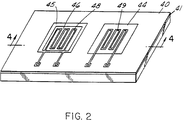
- FIG. 2 is a perspective view of one embodiment of a catalytic differential calorimetric sensor having a silicon frame 40 with two membranes 44 and 45 with temperature measuring layers 48 and 49 placed on top of the membrane. The temperature measuring layers are covered by a passivation layer 41. A catalytic layer 46 is placed on top of membrane 45. The temperature measuring layer 49 on membrane 44 is used to measure the temperature of the surrounding gas, while the temperature measuring layer on membrane 45 measures the additional heat generated by the catalytic layer.
- the membranes 44 and 45 can be made of silicon nitride.
- the preferred embodiment includes membranes made of a composite of silicon nitride and silicon oxide layers, most preferably silicon nitride, silicon oxide and silicon nitride layers.
- Aluminium oxide can be deposited on top of the membrane structure to improve the adhesive properties of the catalytic layer on the membrane.
- the resultant membranes have a low thermal conductivity and are tensile so they stay flat over a wide temperature range without buckling.
- microfabricated catalytic microcalorimeters Figures 2 and 3
- the present invention provides a chemical and more effective means of fabrication using the sol-gel process. Metals are traditionally loaded on the membrane by sputtering; however, this technique can produce only a limited number of active sites for catalytic oxidisation of the combustible gas molecules. This limited number of active catalytic sites might reduce the sensitivity of a catalytic calorimetric gas sensor.
- this invention describes sol-gel methods which increase the number of catalytic sites without increasing the size of the device. The number of catalytic sites are increased by the use of sol-gel processed alumina/silica based materials which provide a high-surface area washcoat having controlled porosity with narrow pore-size distribution.
- the present invention discloses a method to maximise deposition of the catalytically active metal particles in the pores of the washcoat. This method reduces agglomeration of the metal particles available for catalytic reactions. Accordingly, the present invention directed efforts to preparing controlled, small metal particles, using a technique disclosed by Schmid in Chem. Rev. 92 (1992) 1709-1727. With Schmid's technique, small noble particles were stabilised by small organic molecules such as sulphanilic acid salts. Another method for preparing controlled size catalytically active metals includes impregnation, whereby the particles are prepared on the washcoat itself. These small noble metal particles in conjunction with high-surface area alumina-based membranes provide a substantially larger number of catalytic sites for calorimetric sensors as compared to conventional fabrication routes.
- washcoat refers to the supporting material on which the catalytically active metal particles are loaded.
- substrate refers to the material supporting the temperature measuring layer and the catalytic layer.
- the substrate is generally a ceramic 30 or a silicon micromachined structure consisting of a silicon frame 40 and membranes 44 and 45.
- metals which act as catalytically active metals including but not limited to Fe, Cu, Co, Cr, Ni, Mn, Zn, Cd and Ag and mixtures thereof; however, the preferred active metals are generally noble metals.
- Noble metals are preferred in large part due to their stability towards catalyst poisons.
- Noble metals include but are not limited to platinum, palladium, silver, gold, ruthenium, rhodium, osmium, iridium and mixtures thereof.
- alumina sols were prepared by hydrolysing aluminium alkoxides in water followed by peptisation in the presence of dilute mineral acid. The sol was concentrated to a gel which was then heated at 250°C and 600°C in a nitrogen atmosphere. An alumina washcoat was then prepared from the alumina sols and showed a surface area of 230 m/g and a pore size of 45 ⁇ .
- Alumina/silica washcoats were prepared from a mixture of alumina and silica sol which were gelled, dried and aged at 600°C.
- Silica sol was prepared from Si(EtO)4 in ethanol, water and dilute mineral acid.
- the resultant alumina/silica washcoat showed a surface area of 390 m/g and a pore size of 45 ⁇ .
- the alumina/silica washcoat was prepared by treating an alumina washcoat with a silica sol, resulting in a pore size of between 30 and 40 ⁇ .
- alumina/silica materials were prepared from (tBuO)3 Si-O-Al(OR)2, and Al(OR)3 in parent alcohol. These materials also retained a high surface area after aging at 1100°C in air.
- the alumina sol is preferably prepared by Burgraff's method of preparation of supported and unsupported alumina washcoats. Aluminium sec-butoxide is hydrolysed in water and heated to remove iso-propanol. The residue is treated with dilute nitric acid and peptised for sixteen hours to obtain boehemite sol.
- the surface area of bulk gel derived from boehemite sol and fired to 600°C is 200 m/g and pore size is 45 ⁇ .
- Burgraff reports a pore size of 60 ⁇ while our experiments yielded a pore size of 45 ⁇ .
- the concentration and viscosity of alumina sol is then adjusted to make it suitable for deposition on the substrate or alternatively on one of the two membranes (in Figures 2 and 3) of prefabricated wafers by microcapillary device.
- the amount of liquid dispensed and the wetting characteristics of the fluid to the substrate determine the thickness of the alumina washcoat. In practice, it is difficult to generate very small drops, however, part of the liquid can be removed by suction leaving only a controlled amount of alumina on the substrate.
- the sol is slowly heated to 400°C and cooled to room temperature, leaving a thin supported alumina washcoat on the substrate.
- the alumina washcoat prepared by this method, has low residual stress, is rather uniform with the exception of the border region and retains high surface area and porosity.
- the thickness of the alumina washcoat can be varied in the 20-100 nm range and a thicker washcoat can be deposited by repeated applications of alumina sol.
- An advantage of this method is that it results in an alumina washcoat having relative uniformity and thinness which improves thermal contact between the alumina washcoat and the substrate.
- the ability to make a thin layer using the sol-gel process provides good thermal contact between the catalytic layer and the temperature measuring layer.
- a thin layer allows the temperature measuring layer to accurately measure the heat produced by the catalytic layer.
- the preferred method of metal sol preparation includes the use of either platinum or palladium as the metal of choice to produce particles having a small and controlled size as described by Schmid.
- Platinum or palladium sols are prepared by reduction of chloroplatinic or chloropalladic acids in water.
- the sols are then stabilised by treatment with sodium salt of sulphanilic acid.
- metal particles are isolated in solid state (particle size 50-200 ⁇ ) and redissolved in water. Practically any concentration of metal particles in water yields acceptable results.
- Metals are then deposited by microcapillary device on the alumina washcoat of the prefabricated device described above. No further processing is necessary, because the organic component is lost when heated to the operating temperature.
- the uniform small particle size of the metals and the controlled amounts contribute to a large number of catalytic sites on the sensor device.
- the catalytic layer that would be utilised would preferably comprise sol-gel processed catalytically active metal particles in combination with a sol-gel processed washcoat.
- the metal particles can be deposited on the washcoat or mixed with the washcoat.
- sol-gel processed catalytic layer includes: 1) a sol-gel processed washcoat together with sol-gel processed catalytically active metal particles; and 2) a sol-gel processed washcoat together with catalytically active metal particles.
- the preferred method of providing a washcoat on a substrate includes a channelled substrate, such as a honeycomb ceramic structure or the like.
- a channelled substrate such as a honeycomb ceramic structure or the like.
- the disclosure of this method in the 5,210,062 patent disclosed by Narula et al., herein incorporated by reference, showed that the sol-gel process was suitable for deposition of a washcoat on a catalytic honeycomb substrate.
- the '062 patent also demonstrated that the sol-gel process reduced alumina buildup in the corners of the channelled substrate, thereby alleviating the back pressure problem which existed prior to the '062 patent.
- the method disclosed in the '062 patent comprises first applying a coating of a reactive mixture on the substrate.
- a reactive mixture is made by combining a certain type of aluminium alkoxide containing hydrolysable alkoxy groups with water and acid, generally with stirring, wherein a suspension is formed.
- the aluminium alkoxide useful with this invention has the chemical formula: Al(OR)3, wherein R comprises alkyl group, branched alkyl group, or aryl group having between 3 and 6 carbon atoms.
- Aluminium alkoxides which may be used in this invention include, but are not limited to, ethoxides, (n-, or iso)propoxides, (n, sec, or tert-) butoxides, or (n, sec, or tert-) amyloxides.
- the excess coating from the channels can be removed by blowing gas through the channels.
- the reactive coating is then hydrolysed with the addition of water.
- the coating on the substrate is then dried at a temperature suitable to remove water present in the coating, preferably at or below about 100°C.
- the method also includes calcining the coating, preferably at a temperature greater than about 300°C, most preferably between about 300° and 900°C, to densify the coating and convert it to g-alumina.
- the method may additionally comprise repeatedly applying and drying the coating followed by calcining or doing all three steps until a coating of desired surface area is obtained.
- the reactive mixture may further comprise other components such as compatible salts of materials like barium and cerum which would also form oxides thereof in the washcoat.
- compatible salts of materials like barium and cerum which would also form oxides thereof in the washcoat.
- barium oxide and cerium oxide in the washcoat improves the high temperature stability of the washcoat and the oxidation efficiency of the catalytic layer during use.
- the above method provides a more efficient catalyst for combustible sensors.
- the catalytic layer of the calorimetric sensor should be disposed on the substrate such that the catalytic active sites are maximised, and to provide an unrestricted flow of exhaust gases to pass through the catalytic layer.
- the substrate is made preferably of a substantially chemically inert, rigid solid material capable of maintaining its shape and strength at high temperatures.
- the substrate may be metallic or ceramic in nature or a combination thereof. Suitable materials are a-alumina, cordierite, alpha-alumina, and zirconium silicate.
- the preferred substrate is the honeycomb ceramic structure.
- the preferred aluminium alkoxide comprises aluminium tris (sec-butoxide) and the preferred solvent is sec-butanol and the preferred sol is alumina/silica.
- the U.S. 5,134,107 patent issued to Narula herein incorporated by reference, teaches a method for making single phase lanthanide-aluminium-oxide materials. Research has shown that when employing aluminium oxide materials as a catalyst washcoat it is desirable to include lanthanum or cerium atoms or both in the aluminium oxide matrix. Incorporating either or both of those metal atoms in the aluminium matrix tends to prevent structural changes that occur in unstabilised g-alumina at high temperatures, which would tamper with the efficiency of a catalytic sensor. When using sol-gel techniques to make the alumina material, these other metal atoms are added by co-hydrolyzing one or more metal-alkoxides with aluminium alkoxide.
- the '107 patent teaches a method which comprises reacting, according to sol-gel techniques, water and heterobimetallic alkoxides comprising tribis(2-propanolato) alumina) hexakis-(2-propanolato))]lanthanide represented by the general chemical formula Ln[Al(OPri)4]3, Ln being a lanthanide.
- Lanthanide is meant to include the members of the lanthanide series of the periodic table such as lanthanum and cerium.
- the lanthanide-aluminium-oxide materials according to the present invention are made from single phase sols.
- the sol may be made by forming a reaction mixture of the heterobimetallic alkoxides with water, and adding acid to the reaction mixture to form a sol.
- Acids employed embodiments of the present invention may be selected from any organic and inorganic acids which may include, but are not limited to, nitric, hydrochloric, sulphuric, acetic and propionic acid.
- Alcohol is generally employed as a solvent for the alkoxide prior to it being combined with water.
- Alcohols which may be broadly employed according to embodiments of the present invention include 2-propanol, n-butanol and sec-butanol, with 2 propanol being preferred.
- the preferred heterobimetallic peroxide is tris[(bis2-propanolato)alumina)hexakis(a-)2-propanolato))]lanthanum.
- the sol is preferably stabilised by maintaining the reaction mixture for a time and a temperature sufficient to form a stable sol.
- a stable sol is one that maintains its sol properties and does not experience any substantial gelling when exposed to air or moisture for a significant period of time, e.g., months.
- the sol is coated on the substrate and then the coating is dried and subsequently calcined at an elevated temperature.
- calcination is carried out at a temperature above 300°C, preferably between about 300°C and 900°C to form a lanthanide-aluminium-oxide material.
- gels may be made more directly from lanthanum aluminium alkoxide.
- a wet alcohol generally meant to be one containing more than six equivalents of water, to a solution of the alkoxide in an alcohol at room temperature results in gel formation instantaneously at the contact layer.
- sol-gel techniques may also be employed to make aluminium materials comprising more than one lanthanide as a single phase material.
- Alumina sols were also prepared in the '881 patent by hydrolysing aluminium alkoxide (eg. Al(OR3) in water followed by peptisation in the presence of diluted mineral acid. The sol was then concentrated to a gel which was heated at between 250°C and 600°C in a nitrogen atmosphere.
- Alumina/silica washcoats were prepared for a mixture of alumina sol and silica sol which is obtained from Si(ETO)4 in ethanol, water, and diluted mineral acid. A sample of alumina/silica washcoat was then made with uniform pore size around 45 ⁇ and 390m/g.
- the sol-gel processed washcoat can also include as the catalytically active metal, transition-metals.
- silver-containing sol such as AgNO3, which is water soluble was dissolved in distilled water. The silver solution was then used to impregnate the sol-gel washcoat. The ratio of the silver amount to the sol-gel weight was dependent on the desired silver loading on the sol-gel washcoat. After the impregnation, the material was dried up to 120°C and then heated in air inside a furnace of 500 to 600°C for four hours.
- the present invention's preferred method for fabricating a sensitivity enhanced calorimetric device includes using silicon-micromachining. Silicon micromachining offers the capability of fabricating devices with low power consumption at potentially lower manufacturing costs. A micromachined device can also have a faster response time because the membrane temperature measuring layer and the catalytic layer have a smaller thermal mass than conventional calorimetric devices.
- the preferred embodiment includes fabrication of a silicon micromachined differential microcalorimeter.
- the temperature rise is preferably measured differentially by adding a second element with thermal characteristics identical to those of the temperature measuring device, but without a catalytic layer.
- Figure 2 shows a perspective view
- Figure 3 shows a schematic cross-sectional diagram of one of the device configurations fabricated and studied.
- Two thin-film resistors are fabricated on two micromachined membranes of low thermal conductivity, and one is covered by a catalytic layer. For simplicity, no heater was incorporated in the design and the devices were heated externally.
- the average temperature rise in a microcalorimeter is dictated by the balance of heat produced by the chemical reaction and the heat lost to the environment.
- effects such as the reactant mass transfer, the reaction kinetics at the catalyst, the heat loss by conduction/convection to the ambient gas and by conduction to the substrate, thermal fluctuations in the environment, and the electrical characteristics of the thermometer must all be taken into account.
- the key elements of a Si-based microcalorimeter are the catalytic layer, the temperature measuring layer, the heater, and the supporting structure or substrate for all of the previous elements.
- the substrate consists of a bulk silicon frame with either a membrane layer or a more complex plate/teeter element which in both cases are obtained by etching the underlying bulk silicon frame.
- the membrane or plate/teeter acts as a support for the temperature measuring layer.
- Multiple silicon dies can be fabricated from a single silicon wafer.
- the membrane or plate/teeter should have a small thermal mass for fast response time, but must be mechanically robust to support the temperature measuring layer and the catalytic layer and survive temperature cycling, pressure shocks, water mist and small particle impingement.
- the catalytic layer should have a large specific surface area for the device to operate in mass-transport limited regime. This surface area is achieved by using sol-gel processed alumina-silica washcoat and/or sol-gel processed catalytically active metal particles.
- the catalytic layer should not substantially change the thermal characteristics of the membrane, otherwise the sensor temperature compensation may be compromised.
- the temperature measuring layer should mainly measure the central region of the membrane where the temperature rise due to the reaction is the largest, without substantially contributing to conductive heat loss.
- a thin-film resistor with stable resistance and temperature coefficient of resistance (TCR) is desirable as the temperature measuring layer.
- the film resistor is patterned as a winding element to increase its resistance (i.e., the output signal) and distribute the stress induced by the thermal mismatch with the membrane.
- One method includes using a micro syringe to deposit the catalytic layer onto the membrane. With this method, the catalytic layer is deposited to create catalytic active sites specifically at the desired locations. Although this technique provides accurate deposition of the catalytic layer, this technique may not be suitable for mass manufacturing.
- a second method involves dipping the silicon wafer into a sol-gel solution to coat the silicon die with a sol-gel processed catalytic layer.
- This second method is preferred as it provides a controllable and efficient method to batch fabricate catalytic calorimetric gas sensors in a way that is compatible with silicon micromachined structures.
- the thickness of the catalytic layer can be readily controlled by varying the speed with which the silicon wafer is immersed and removed from the sol-gel solution.
- This dipping method further requires removal of the sol-gel catalytic layer from specific areas to create the catalytic active sites at the specific desired locations. Selective removal of the catalytic layer can be effectuated in two ways.
- This step is then followed by washing the sol-gel catalytic layer with a solvent to strip the remaining sol-gel solution from the catalytic layer.
- An acid solvent could strip the solution from the undesired locations.
- the result in either case is a silicon wafer having a sol-gel processed catalytic layer selectively placed thereon that is easily reproducible.
- the preferred method includes dipping the silicon wafer and then etching away the sol-gel solution from the undesired locations.
- the membrane is deposited first on a silicon wafer, 100 mm in diameter, 400 mm thick.
- the membrane is in total preferably between 500 - 1000 nm, such that it is mechanically stable while being thin enough to prevent loss of heat by thermal conduction through the substrate.
- LPCVD low pressure chemical vapour deposition
- PECVD plasma enhanced chemical vapour deposition
- the latter composite layer After annealing at 600°C, the latter composite layer has a small residual stress (tensile) of about 6x10⁸ dynes/cm, the compressive state of the oxide being compensated by the tensile nitride.
- a Pt film resistance thermometer 100 nm thick, is sputter deposited.
- the film resistors acting as temperature measuring devices and/or heaters, are delineated by lithography and wet etching.
- the wafers After annealing the Pt resistors at 500°C in nitrogen to stabilise their resistance and temperature coefficient of resistance (TCR), the wafers are coated with 0.2-0.3 mm of PECVD silicon nitride for passivation and annealed at 500°C.
- the passivation is then removed on the contact pads with plasma etching. While defining the opening for the contact pads, an etch-mask pattern is also defined on the back side of the wafer using a double-sided aligner. A 30% aqueous solution of KOH at 80°C is used to completely etch the silicon underneath the membrane. The membrane has sufficient mechanical strength to allow the wafer to be diced with a diamond saw. For ease of handling, a die size of 7x7 mm is used, although only a 3.5 x 3.5 mm area is needed for the device with the smallest membrane.
Landscapes
- Chemical & Material Sciences (AREA)
- Engineering & Computer Science (AREA)
- Ceramic Engineering (AREA)
- Organic Chemistry (AREA)
- Structural Engineering (AREA)
- Materials Engineering (AREA)
- Life Sciences & Earth Sciences (AREA)
- Health & Medical Sciences (AREA)
- General Health & Medical Sciences (AREA)
- General Physics & Mathematics (AREA)
- Immunology (AREA)
- Pathology (AREA)
- Analytical Chemistry (AREA)
- Biochemistry (AREA)
- Physics & Mathematics (AREA)
- Combustion & Propulsion (AREA)
- Chemical Kinetics & Catalysis (AREA)
- Electrochemistry (AREA)
- Catalysts (AREA)
- Investigating Or Analyzing Materials Using Thermal Means (AREA)
- Investigating Or Analyzing Materials By The Use Of Electric Means (AREA)
Applications Claiming Priority (2)
| Application Number | Priority Date | Filing Date | Title |
|---|---|---|---|
| US08/311,299 US5707148A (en) | 1994-09-23 | 1994-09-23 | Catalytic calorimetric gas sensor |
| US311299 | 1994-09-23 |
Publications (2)
| Publication Number | Publication Date |
|---|---|
| EP0703449A1 true EP0703449A1 (de) | 1996-03-27 |
| EP0703449B1 EP0703449B1 (de) | 2003-06-11 |
Family
ID=23206284
Family Applications (1)
| Application Number | Title | Priority Date | Filing Date |
|---|---|---|---|
| EP95306628A Expired - Lifetime EP0703449B1 (de) | 1994-09-23 | 1995-09-20 | Katalytischer Wärmetönungsgassensor |
Country Status (4)
| Country | Link |
|---|---|
| US (2) | US5707148A (de) |
| EP (1) | EP0703449B1 (de) |
| JP (1) | JPH08304320A (de) |
| DE (1) | DE69531031T2 (de) |
Cited By (10)
| Publication number | Priority date | Publication date | Assignee | Title |
|---|---|---|---|---|
| EP0819935A1 (de) * | 1996-07-19 | 1998-01-21 | Fraunhofer-Gesellschaft Zur Förderung Der Angewandten Forschung E.V. | Katalytisches Gassensorelement |
| WO1999026051A2 (en) | 1997-11-14 | 1999-05-27 | Motorola Inc. | Calorimetric hydrocarbon gas sensor |
| WO2000043765A1 (en) * | 1999-01-25 | 2000-07-27 | Mine Safety Appliances Company | Gas sensor |
| WO2005052564A1 (en) * | 2003-11-21 | 2005-06-09 | General Electric Company | Miniaturized multi-gas and vapor sensor devices and associated methods of fabrication |
| US20110107817A1 (en) * | 2009-11-06 | 2011-05-12 | Andreas Krauss | Particle sensor |
| WO2016066003A1 (zh) * | 2014-10-31 | 2016-05-06 | 中国矿业大学 | 基于硅加热器的mems甲烷传感器及其制备方法与应用 |
| US10234412B2 (en) | 2016-11-04 | 2019-03-19 | Msa Technology, Llc | Identification of combustible gas species via pulsed operation of a combustible gas sensor |
| US10761040B2 (en) | 2015-04-29 | 2020-09-01 | Rosneft Oil Company | Planar thermocatalytic sensor of combustable gases and vapours |
| US10900922B2 (en) | 2018-07-17 | 2021-01-26 | Msa Technology, Llc | Power reduction in combustible gas sensors |
| US11703473B2 (en) | 2019-12-11 | 2023-07-18 | Msa Technology, Llc | Operation of combustible gas sensor in a dynamic mode with a constant resistance setpoint |
Families Citing this family (70)
| Publication number | Priority date | Publication date | Assignee | Title |
|---|---|---|---|---|
| US5804462A (en) * | 1995-11-30 | 1998-09-08 | Motorola, Inc. | Method for forming a multiple-sensor semiconductor chip |
| US6196052B1 (en) * | 1996-01-17 | 2001-03-06 | Advanced Technology Materials, Inc. | Piezoelectric gas sensing device for detection of a gas species a gaseous environment |
| WO1998015818A1 (en) * | 1996-10-10 | 1998-04-16 | Samsung Electronics Co., Ltd. | Hybrid integrated circuit for a gas sensor |
| JP3377162B2 (ja) * | 1997-01-17 | 2003-02-17 | 株式会社リコー | 熱分析装置およびその計測方法 |
| DE19710946A1 (de) * | 1997-03-15 | 1998-09-24 | Braun Ag | Thermopile-Sensor und Strahlungsthermometer mit einem Thermopile-Sensor |
| US6079873A (en) * | 1997-10-20 | 2000-06-27 | The United States Of America As Represented By The Secretary Of Commerce | Micron-scale differential scanning calorimeter on a chip |
| DE19752208A1 (de) * | 1997-11-25 | 1999-06-02 | Bosch Gmbh Robert | Thermischer Membransensor und Verfahren zu seiner Herstellung |
| EP0921391A1 (de) * | 1997-12-05 | 1999-06-09 | Interuniversitair Micro-Elektronica Centrum Vzw | Vorrichtung und Verfahren zur thermischen Messung |
| US6545334B2 (en) | 1997-12-19 | 2003-04-08 | Imec Vzw | Device and a method for thermal sensing |
| US20060186438A1 (en) * | 1997-12-19 | 2006-08-24 | Vivactis N.V. | Device for thermal sensing |
| US6003307A (en) * | 1998-02-06 | 1999-12-21 | Engelhard Corporation | OBD calorimetric sensor system with offset error correction |
| US5996337A (en) * | 1998-02-06 | 1999-12-07 | Engelhard Corporation | Dynamic calorimetric sensor system |
| DE19808248A1 (de) * | 1998-02-27 | 1999-09-02 | Pierburg Ag | Meßvorrichtung zur Messung der Masse eines strömenden Mediums |
| US6494090B1 (en) * | 1998-05-05 | 2002-12-17 | Pierburg Ag | Air-mass sensor |
| US6344173B1 (en) * | 1998-12-07 | 2002-02-05 | Corning Incorporated | Automotive hydrocarbon sensor |
| US6238085B1 (en) * | 1998-12-31 | 2001-05-29 | Honeywell International Inc. | Differential thermal analysis sensor |
| JP3466103B2 (ja) * | 1999-03-16 | 2003-11-10 | 松下電器産業株式会社 | 触媒燃焼装置 |
| US6436346B1 (en) * | 1999-09-14 | 2002-08-20 | U T Battelle, Llc | Micro-machined calorimetric biosensors |
| JP3765951B2 (ja) * | 1999-09-29 | 2006-04-12 | 矢崎総業株式会社 | 接触燃焼式ガスセンサ並びにガス検出方法及びその装置 |
| JP2001099801A (ja) * | 1999-09-29 | 2001-04-13 | Yazaki Corp | 接触燃焼式ガスセンサ |
| US6690569B1 (en) * | 1999-12-08 | 2004-02-10 | Sensirion A/G | Capacitive sensor |
| JP2001264441A (ja) * | 2000-01-14 | 2001-09-26 | Seiko Instruments Inc | カロリーメーターとその製造方法 |
| FI20000917A0 (fi) * | 2000-04-17 | 2000-04-17 | Valtion Teknillinen | Anturi ja menetelmä kaasujen pitoisuuden mittaamiseksi |
| US6474138B1 (en) * | 2000-11-28 | 2002-11-05 | Honeywell International Inc. | Adsorption based carbon monoxide sensor and method |
| US6550310B1 (en) | 2000-11-28 | 2003-04-22 | Honeywell International Inc. | Catalytic adsorption and oxidation based carbon monoxide sensor and detection method |
| DE10065723A1 (de) * | 2000-12-29 | 2002-07-04 | Bosch Gmbh Robert | Anordnung zur Temperaturmessung und -regelung |
| US20020142478A1 (en) * | 2001-03-28 | 2002-10-03 | Hiroyuki Wado | Gas sensor and method of fabricating a gas sensor |
| AU2002355079C1 (en) * | 2001-07-16 | 2008-03-06 | Sensor Tech, Inc. | Sensor device and method for qualitative and quantitative analysis of gas phase substances |
| GB0117376D0 (en) * | 2001-07-17 | 2001-09-05 | Amersham Pharm Biotech Uk Ltd | Thermocouple device |
| US6759358B2 (en) | 2001-08-21 | 2004-07-06 | Sud-Chemie Inc. | Method for washcoating a catalytic material onto a monolithic structure |
| US6921594B2 (en) * | 2001-12-19 | 2005-07-26 | Sud-Chemie Inc. | Exhaust treatment and filtration system for molten carbonate fuel cells |
| US7833800B2 (en) * | 2002-04-01 | 2010-11-16 | Palo Alto Research Center Incorporated | Thermal sensing with bridge circuitry |
| US7754492B2 (en) * | 2002-04-01 | 2010-07-13 | Palo Alto Research Center Incorporated | Thermal sensing device |
| US7473030B2 (en) * | 2002-04-01 | 2009-01-06 | Palo Alto Research Center Incorporated | Thermal sensing |
| US7473031B2 (en) * | 2002-04-01 | 2009-01-06 | Palo Alto Research Center, Incorporated | Resistive thermal sensing |
| JP4009520B2 (ja) * | 2002-11-05 | 2007-11-14 | 日東電工株式会社 | 温度測定用フレキシブル配線回路基板 |
| US7159444B2 (en) * | 2002-11-26 | 2007-01-09 | Proton Energy Systems, Inc. | Combustible gas detection systems and method thereof |
| US7111493B2 (en) * | 2002-11-26 | 2006-09-26 | Proton Energy Systems, Inc. | Combustible gas detection system |
| US7526942B2 (en) * | 2003-06-12 | 2009-05-05 | Riken Keiki Co., Ltd. | Contact combustion gas sensor |
| KR100523516B1 (ko) * | 2003-07-07 | 2005-10-25 | 엘지전자 주식회사 | 박막형 이산화탄소 가스 센서 |
| US20060151332A1 (en) * | 2003-12-05 | 2006-07-13 | Proton Energy Systems, Inc. | Combustible gas detection system |
| WO2005088285A1 (ja) * | 2004-03-17 | 2005-09-22 | National Institute Of Advanced Industrial Science And Technology | マイクロ熱電式ガスセンサ |
| US6988826B2 (en) * | 2004-05-17 | 2006-01-24 | General Electric Company | Nano-calorimeter device and associated methods of fabrication and use |
| DE602005000853D1 (de) * | 2004-07-02 | 2007-05-24 | Vivactis Nv | Messung der Wärme erzeugt durch einen chemischen oder biologischen Prozess. |
| JP2006058078A (ja) * | 2004-08-18 | 2006-03-02 | Hitachi Ltd | 熱式空気流量計 |
| EP1717566A1 (de) * | 2005-04-25 | 2006-11-02 | Mettler-Toledo AG | Thermoanalytischer Sensor |
| JP4801396B2 (ja) * | 2005-09-01 | 2011-10-26 | 敏嗣 植田 | ガスセンサ及びガスセンサの製造方法 |
| US20080273572A1 (en) * | 2006-06-02 | 2008-11-06 | James Madison University | Thermal detector for chemical or biological agents |
| US7833482B2 (en) | 2006-12-29 | 2010-11-16 | Honeywell International Inc. | Low power combustible gas sensor |
| US20100221148A1 (en) * | 2007-03-28 | 2010-09-02 | Horiba, Ltd. | Combustible gas sensor |
| WO2008123092A1 (ja) * | 2007-03-28 | 2008-10-16 | Horiba, Ltd. | 可燃性ガスセンサ |
| KR100896482B1 (ko) | 2007-05-28 | 2009-05-08 | 연세대학교 산학협력단 | 열센서를 이용한 가스센서 및 그 제조 방법 |
| US7632008B2 (en) * | 2007-06-08 | 2009-12-15 | Palo Alto Research Center Incorporated | Ranking fragment types with calorimetry |
| DE102007032058A1 (de) * | 2007-07-10 | 2009-01-22 | Continental Automotive Gmbh | Sensor mit einer Messstelle, die von einem Passivierungsmittel bedeckt ist |
| WO2009157123A1 (ja) * | 2008-06-26 | 2009-12-30 | 株式会社 村田製作所 | センサ装置及びその製造方法 |
| EP2565635B1 (de) | 2011-09-02 | 2017-11-15 | Sensirion AG | Sensorchip und Verfahren zur Herstellung eines Sensorchips |
| DE102012209620B4 (de) * | 2012-06-08 | 2023-01-19 | Robert Bosch Gmbh | Verfahren zum Herstellen eines Sensorträgers, Sensorträger und Sensor |
| KR102154291B1 (ko) * | 2013-03-27 | 2020-09-09 | 인텔렉추얼디스커버리 주식회사 | 수소센서 및 그 제조 방법 |
| DE102013217465A1 (de) * | 2013-09-02 | 2015-03-05 | Continental Automotive Gmbh | Sensor zur Detektion oxidierbarer Gase |
| US9366557B2 (en) * | 2013-12-04 | 2016-06-14 | Itron, Inc. | Thermal flow sensors having isolated membranes |
| US9970914B1 (en) | 2014-04-04 | 2018-05-15 | The United States Of America As Represented By The Administrator Of National Aeronautics And Space Administration | Gas sensors with contact pads |
| DE102014018681B3 (de) | 2014-12-18 | 2015-10-29 | Dräger Safety AG & Co. KGaA | Gassensor und Verfahren zur Herstellung eines Messelementes |
| EP3277410A4 (de) * | 2015-03-24 | 2019-02-20 | Tecogen, Inc. | Giftresistenter katalysator und systeme damit |
| US20200096396A1 (en) | 2018-09-26 | 2020-03-26 | Ams Sensors Uk Limited | Gas Sensors |
| US11543396B2 (en) * | 2019-06-11 | 2023-01-03 | Msa Technology, Llc | Gas sensor with separate contaminant detection element |
| DE102020134366A1 (de) | 2020-12-21 | 2022-06-23 | Infineon Technologies Ag | Sensor zum Messen einer Gaseigenschaft |
| DE102022102969A1 (de) * | 2021-02-22 | 2022-08-25 | Dräger Safety AG & Co. KGaA | Gasdetektionsvorrichtung mit einem Detektor und einem Kompensator und Gasdetektionsverfahren mit einer solchen Gasdetektionsvorrichtung |
| US12535363B2 (en) * | 2022-07-28 | 2026-01-27 | Applied Materials, Inc. | Radical sensor substrate |
| CN116718645A (zh) * | 2023-05-23 | 2023-09-08 | 浙江工业大学 | 一种基于多孔氧化铝支撑体的高响应灵敏度催化燃烧式氢气传感器及其制备方法 |
| US20240393305A1 (en) * | 2023-05-24 | 2024-11-28 | The Penn State Research Foundation | Vanadium oxide-doped laser-induced graphene multi-parameter sensor to decouple soil nitrogen loss and temperature |
Citations (10)
| Publication number | Priority date | Publication date | Assignee | Title |
|---|---|---|---|---|
| JPS55156850A (en) * | 1979-05-24 | 1980-12-06 | Matsushita Electric Ind Co Ltd | Manufacture of compensating element for inflammable gas detector |
| US4355056A (en) | 1981-03-31 | 1982-10-19 | The Babcock & Wilcox Company | Method of manufacturing a combustibles sensor |
| US4579751A (en) * | 1983-08-30 | 1986-04-01 | Cerberus Ag | Method of producing constituent materials for gas sensors |
| JPH01145561A (ja) * | 1987-12-01 | 1989-06-07 | Fuji Electric Co Ltd | ガスセンサ |
| US4839327A (en) * | 1987-04-08 | 1989-06-13 | Agency Of Industrial Science & Technology | Method for the production of ultra-fine gold particles immobilized on a metal oxide |
| DE3839414A1 (de) * | 1988-11-22 | 1990-05-23 | Siemens Ag | Sensoranordnung zum nachweis von gasen durch exotherme katalytische reaktionen |
| GB2238617A (en) * | 1989-11-28 | 1991-06-05 | Eev Ltd | Detector for flammable gases |
| US5134107A (en) | 1991-09-06 | 1992-07-28 | Ford Motor Company | Single phase metal-alumina made by sol-gel processing |
| WO1993003840A1 (en) * | 1991-08-26 | 1993-03-04 | Ford Motor Company Limited | Aluminum oxide catalyst supports from alumina sols |
| US5234881A (en) | 1992-06-05 | 1993-08-10 | Ford Motor Company | Binary LA-PA oxide catalyst and method of making the catalyst |
Family Cites Families (10)
| Publication number | Priority date | Publication date | Assignee | Title |
|---|---|---|---|---|
| US4378385A (en) * | 1980-03-28 | 1983-03-29 | United Kingdom Atomic Energy Authority | Method of making oxygen ion conducting solid electrolyte device |
| JPS6028826A (ja) * | 1983-07-26 | 1985-02-14 | Hiroshi Suzuki | かご型ゼオライト薄膜表層を有する複合膜及びその製造法 |
| US4560585A (en) * | 1983-12-23 | 1985-12-24 | Rexnord Inc. | Poison resistant combustible gas sensor |
| JPH0823535B2 (ja) * | 1987-04-13 | 1996-03-06 | セイコー電子工業株式会社 | 示差走査熱量計 |
| IL93134A (en) * | 1990-01-23 | 1997-11-20 | Yissum Res Dev Co | Doped sol-gel glasses for obtaining chemical interactions |
| DE4133337A1 (de) * | 1990-10-08 | 1992-04-09 | Riken Kk | Abgasreiniger und verfahren zum reinigen von abgasen |
| US5265417A (en) * | 1993-01-07 | 1993-11-30 | Ford Motor Company | Method and apparatus for determining the hydrocarbon conversion efficiency of a catalytic converter |
| US5451371A (en) * | 1994-06-09 | 1995-09-19 | Ford Motor Company | High-sensitivity, silicon-based, microcalorimetric gas sensor |
| US5480622A (en) * | 1994-07-05 | 1996-01-02 | Ford Motor Company | Electrically heatable catalyst device using electrically conductive non-metallic materials |
| US5431012A (en) * | 1994-07-05 | 1995-07-11 | Ford Motor Company | System for monitoring the performance of automotive catalysts |
-
1994
- 1994-09-23 US US08/311,299 patent/US5707148A/en not_active Expired - Fee Related
-
1995
- 1995-08-03 JP JP7198242A patent/JPH08304320A/ja active Pending
- 1995-09-20 DE DE69531031T patent/DE69531031T2/de not_active Expired - Fee Related
- 1995-09-20 EP EP95306628A patent/EP0703449B1/de not_active Expired - Lifetime
-
1997
- 1997-09-29 US US08/940,144 patent/US5813764A/en not_active Expired - Fee Related
Patent Citations (11)
| Publication number | Priority date | Publication date | Assignee | Title |
|---|---|---|---|---|
| JPS55156850A (en) * | 1979-05-24 | 1980-12-06 | Matsushita Electric Ind Co Ltd | Manufacture of compensating element for inflammable gas detector |
| US4355056A (en) | 1981-03-31 | 1982-10-19 | The Babcock & Wilcox Company | Method of manufacturing a combustibles sensor |
| US4579751A (en) * | 1983-08-30 | 1986-04-01 | Cerberus Ag | Method of producing constituent materials for gas sensors |
| US4839327A (en) * | 1987-04-08 | 1989-06-13 | Agency Of Industrial Science & Technology | Method for the production of ultra-fine gold particles immobilized on a metal oxide |
| JPH01145561A (ja) * | 1987-12-01 | 1989-06-07 | Fuji Electric Co Ltd | ガスセンサ |
| DE3839414A1 (de) * | 1988-11-22 | 1990-05-23 | Siemens Ag | Sensoranordnung zum nachweis von gasen durch exotherme katalytische reaktionen |
| GB2238617A (en) * | 1989-11-28 | 1991-06-05 | Eev Ltd | Detector for flammable gases |
| WO1993003840A1 (en) * | 1991-08-26 | 1993-03-04 | Ford Motor Company Limited | Aluminum oxide catalyst supports from alumina sols |
| US5210062A (en) | 1991-08-26 | 1993-05-11 | Ford Motor Company | Aluminum oxide catalyst supports from alumina sols |
| US5134107A (en) | 1991-09-06 | 1992-07-28 | Ford Motor Company | Single phase metal-alumina made by sol-gel processing |
| US5234881A (en) | 1992-06-05 | 1993-08-10 | Ford Motor Company | Binary LA-PA oxide catalyst and method of making the catalyst |
Non-Patent Citations (10)
| Title |
|---|
| BRINKER C J ET AL: "SOL-GEL THIN FILM FORMATION", JOURNAL OF THE CERAMIC SOCIETY OF JAPAN, INTERNATIONAL EDITION, vol. 99, no. 10, 1 October 1991 (1991-10-01), TOKYO JP, pages 843 - 856, XP000263313 * |
| DATABASE WPI Section Ch Week 8107, Derwent World Patents Index; Class J04, AN 81-10434D * |
| DATABASE WPI Section Ch Week 8929, Derwent World Patents Index; Class J04, AN 89-209464 * |
| GALL M: "THE SI-PLANAR-PELLISTOR ARRAY, A DETECTION UNIT FOR COMBUSTIBLE GASES", SENSORS AND ACTUATORS B, vol. B16, no. 1-3, 1 October 1993 (1993-10-01), LAUSANNE CH, pages 260 - 264, XP000411353 * |
| PARK S-S ET AL: "ETHANOL GAS SENSING PROPERTIES OF SnO2-BASED THIN-FILM SENSORS PREPARED BY THE SOL-GEL PROCESS", MATERIALS LETTERS, vol. 17, no. 6, AMSTERDAM NL, pages 346 - 352, XP000413387 * |
| PATENT ABSTRACTS OF JAPAN vol. 13, no. 403 (P - 929) 7 September 1989 (1989-09-07) * |
| PATENT ABSTRACTS OF JAPAN vol. 5, no. 32 (P - 050) 27 February 1981 (1981-02-27) * |
| SCHMID G: "LARGE CLUSTERS AND COLLOIDS. METALS IN THE EMBRYONIC STATE", CHEMICAL REVIEWS, vol. 92, no. 8, EASTON US, pages 1709 - 1727 * |
| SCHMID, CHEM. REV., vol. 92, 1992, pages 1709 - 1727 |
| W. HEMMINGER, CALORIMETRY FUNDAMENTALS AND PRACTICE, 1984 |
Cited By (17)
| Publication number | Priority date | Publication date | Assignee | Title |
|---|---|---|---|---|
| EP0819935A1 (de) * | 1996-07-19 | 1998-01-21 | Fraunhofer-Gesellschaft Zur Förderung Der Angewandten Forschung E.V. | Katalytisches Gassensorelement |
| WO1999026051A2 (en) | 1997-11-14 | 1999-05-27 | Motorola Inc. | Calorimetric hydrocarbon gas sensor |
| EP0966661A4 (de) * | 1997-11-14 | 2006-07-26 | Motorola Inc | Kalorimetrischeer kohlenwasserstoffgassensor |
| WO2000043765A1 (en) * | 1999-01-25 | 2000-07-27 | Mine Safety Appliances Company | Gas sensor |
| US6344174B1 (en) | 1999-01-25 | 2002-02-05 | Mine Safety Appliances Company | Gas sensor |
| WO2005052564A1 (en) * | 2003-11-21 | 2005-06-09 | General Electric Company | Miniaturized multi-gas and vapor sensor devices and associated methods of fabrication |
| US7104113B2 (en) | 2003-11-21 | 2006-09-12 | General Electric Company | Miniaturized multi-gas and vapor sensor devices and associated methods of fabrication |
| US8800350B2 (en) * | 2009-11-06 | 2014-08-12 | Robert Bosch Gmbh | Particle sensor |
| US20110107817A1 (en) * | 2009-11-06 | 2011-05-12 | Andreas Krauss | Particle sensor |
| WO2016066003A1 (zh) * | 2014-10-31 | 2016-05-06 | 中国矿业大学 | 基于硅加热器的mems甲烷传感器及其制备方法与应用 |
| US10761040B2 (en) | 2015-04-29 | 2020-09-01 | Rosneft Oil Company | Planar thermocatalytic sensor of combustable gases and vapours |
| US10234412B2 (en) | 2016-11-04 | 2019-03-19 | Msa Technology, Llc | Identification of combustible gas species via pulsed operation of a combustible gas sensor |
| US10705041B2 (en) | 2016-11-04 | 2020-07-07 | Msa Technology, Llc | Identification of combustible gas species via pulsed operation of a combustible gas sensor |
| US10900922B2 (en) | 2018-07-17 | 2021-01-26 | Msa Technology, Llc | Power reduction in combustible gas sensors |
| US12529668B2 (en) | 2018-07-17 | 2026-01-20 | Msa Technology, Llc | Power reduction in combustible gas sensors |
| US11703473B2 (en) | 2019-12-11 | 2023-07-18 | Msa Technology, Llc | Operation of combustible gas sensor in a dynamic mode with a constant resistance setpoint |
| US12061161B2 (en) | 2019-12-11 | 2024-08-13 | Msa Technology, Llc | Operation of combustible gas sensor in a dynamic mode with a constant resistance setpoint |
Also Published As
| Publication number | Publication date |
|---|---|
| US5813764A (en) | 1998-09-29 |
| DE69531031D1 (de) | 2003-07-17 |
| EP0703449B1 (de) | 2003-06-11 |
| JPH08304320A (ja) | 1996-11-22 |
| US5707148A (en) | 1998-01-13 |
| DE69531031T2 (de) | 2003-11-27 |
Similar Documents
| Publication | Publication Date | Title |
|---|---|---|
| EP0703449B1 (de) | Katalytischer Wärmetönungsgassensor | |
| US6705152B2 (en) | Nanostructured ceramic platform for micromachined devices and device arrays | |
| EP0722565A1 (de) | Katalytischergassensor | |
| Gong et al. | Micromachined nanocrystalline SnO2 chemical gas sensors for electronic nose | |
| JP2829416B2 (ja) | 感ガス素子 | |
| Heule et al. | Miniaturised arrays of tin oxide gas sensors on single microhotplate substrates fabricated by micromolding in capillaries | |
| US5599584A (en) | Microminiature combustible gas sensor and method of fabricating a microminiature combustible gas sensor | |
| Kalinin et al. | High performance microheater-based catalytic hydrogen sensors fabricated on porous anodic alumina substrates | |
| Esfandyarpour et al. | High sensitivity Pt-doped SnO2 gas sensors fabricated using sol–gel solution on micromachined (1 0 0) Si substrates | |
| CN102441375B (zh) | 均相介孔氧化铑/氧化铝复合催化材料及制备方法和应用 | |
| JP3795944B2 (ja) | 半導体式ガスセンサの製造方法 | |
| US4193964A (en) | Microminiature palladium oxide gas detector and method of making same | |
| DE69601930T2 (de) | Katalytisches Gassensorelement | |
| EP1114207B1 (de) | Pellistor | |
| CN118387829A (zh) | 一种基于氧化镍量子点材料的氢气传感器的制备方法 | |
| US4296399A (en) | Microminiature palladium oxide gas detector and method of making same | |
| Cavicchi et al. | Microhotplate gas sensor arrays | |
| Khan et al. | Fabrication of nanostructured metal oxide thin film capacitive humidity sensor | |
| JP3777749B2 (ja) | ガスセンサ | |
| JPH04269650A (ja) | 酸化物半導体ガスセンサ | |
| An et al. | Progress of research on preparation of micro gas sensors of metal oxide semiconductors | |
| JPH07104309B2 (ja) | ガスセンサの製造方法 | |
| SU1557505A1 (ru) | Способ изготовлени сравнительного чувствительного элемента термокаталитического датчика | |
| Nakouzi et al. | Sol-Gel Processed Alumina Based Materials in Microcalorimeter Sensor Device Fabrication for Automotive Applications | |
| Renault et al. | Integration of a sensitive material to a silicon-based device for CO detection |
Legal Events
| Date | Code | Title | Description |
|---|---|---|---|
| PUAI | Public reference made under article 153(3) epc to a published international application that has entered the european phase |
Free format text: ORIGINAL CODE: 0009012 |
|
| AK | Designated contracting states |
Kind code of ref document: A1 Designated state(s): DE FR GB |
|
| 17P | Request for examination filed |
Effective date: 19960807 |
|
| 17Q | First examination report despatched |
Effective date: 20000301 |
|
| GRAH | Despatch of communication of intention to grant a patent |
Free format text: ORIGINAL CODE: EPIDOS IGRA |
|
| GRAH | Despatch of communication of intention to grant a patent |
Free format text: ORIGINAL CODE: EPIDOS IGRA |
|
| GRAA | (expected) grant |
Free format text: ORIGINAL CODE: 0009210 |
|
| AK | Designated contracting states |
Designated state(s): DE FR GB |
|
| REG | Reference to a national code |
Ref country code: GB Ref legal event code: FG4D |
|
| REF | Corresponds to: |
Ref document number: 69531031 Country of ref document: DE Date of ref document: 20030717 Kind code of ref document: P |
|
| PGFP | Annual fee paid to national office [announced via postgrant information from national office to epo] |
Ref country code: GB Payment date: 20030827 Year of fee payment: 9 |
|
| PGFP | Annual fee paid to national office [announced via postgrant information from national office to epo] |
Ref country code: DE Payment date: 20030903 Year of fee payment: 9 |
|
| PGFP | Annual fee paid to national office [announced via postgrant information from national office to epo] |
Ref country code: FR Payment date: 20030904 Year of fee payment: 9 |
|
| ET | Fr: translation filed | ||
| PLBE | No opposition filed within time limit |
Free format text: ORIGINAL CODE: 0009261 |
|
| STAA | Information on the status of an ep patent application or granted ep patent |
Free format text: STATUS: NO OPPOSITION FILED WITHIN TIME LIMIT |
|
| 26N | No opposition filed |
Effective date: 20040312 |
|
| PG25 | Lapsed in a contracting state [announced via postgrant information from national office to epo] |
Ref country code: GB Free format text: LAPSE BECAUSE OF NON-PAYMENT OF DUE FEES Effective date: 20040920 |
|
| PG25 | Lapsed in a contracting state [announced via postgrant information from national office to epo] |
Ref country code: DE Free format text: LAPSE BECAUSE OF NON-PAYMENT OF DUE FEES Effective date: 20050401 |
|
| GBPC | Gb: european patent ceased through non-payment of renewal fee |
Effective date: 20040920 |
|
| PG25 | Lapsed in a contracting state [announced via postgrant information from national office to epo] |
Ref country code: FR Free format text: LAPSE BECAUSE OF NON-PAYMENT OF DUE FEES Effective date: 20050531 |
|
| REG | Reference to a national code |
Ref country code: FR Ref legal event code: ST |