EP0703456A2 - Méthode et dispositif pour l'analyse automatique d'un échantillon - Google Patents
Méthode et dispositif pour l'analyse automatique d'un échantillon Download PDFInfo
- Publication number
- EP0703456A2 EP0703456A2 EP95402117A EP95402117A EP0703456A2 EP 0703456 A2 EP0703456 A2 EP 0703456A2 EP 95402117 A EP95402117 A EP 95402117A EP 95402117 A EP95402117 A EP 95402117A EP 0703456 A2 EP0703456 A2 EP 0703456A2
- Authority
- EP
- European Patent Office
- Prior art keywords
- vial
- assay
- specimen
- stock
- dispensing
- Prior art date
- Legal status (The legal status is an assumption and is not a legal conclusion. Google has not performed a legal analysis and makes no representation as to the accuracy of the status listed.)
- Granted
Links
Images


Classifications
-
- G—PHYSICS
- G01—MEASURING; TESTING
- G01N—INVESTIGATING OR ANALYSING MATERIALS BY DETERMINING THEIR CHEMICAL OR PHYSICAL PROPERTIES
- G01N35/00—Automatic analysis not limited to methods or materials provided for in any single one of groups G01N1/00 - G01N33/00; Handling materials therefor
- G01N35/00584—Control arrangements for automatic analysers
- G01N35/00594—Quality control, including calibration or testing of components of the analyser
- G01N35/00603—Reinspection of samples
-
- G—PHYSICS
- G01—MEASURING; TESTING
- G01N—INVESTIGATING OR ANALYSING MATERIALS BY DETERMINING THEIR CHEMICAL OR PHYSICAL PROPERTIES
- G01N35/00—Automatic analysis not limited to methods or materials provided for in any single one of groups G01N1/00 - G01N33/00; Handling materials therefor
- G01N35/02—Automatic analysis not limited to methods or materials provided for in any single one of groups G01N1/00 - G01N33/00; Handling materials therefor using a plurality of sample containers moved by a conveyor system past one or more treatment or analysis stations
- G01N35/025—Automatic analysis not limited to methods or materials provided for in any single one of groups G01N1/00 - G01N33/00; Handling materials therefor using a plurality of sample containers moved by a conveyor system past one or more treatment or analysis stations having a carousel or turntable for reaction cells or cuvettes
-
- G—PHYSICS
- G01—MEASURING; TESTING
- G01N—INVESTIGATING OR ANALYSING MATERIALS BY DETERMINING THEIR CHEMICAL OR PHYSICAL PROPERTIES
- G01N35/00—Automatic analysis not limited to methods or materials provided for in any single one of groups G01N1/00 - G01N33/00; Handling materials therefor
- G01N35/02—Automatic analysis not limited to methods or materials provided for in any single one of groups G01N1/00 - G01N33/00; Handling materials therefor using a plurality of sample containers moved by a conveyor system past one or more treatment or analysis stations
- G01N35/04—Details of the conveyor system
- G01N2035/0439—Rotary sample carriers, i.e. carousels
- G01N2035/0443—Rotary sample carriers, i.e. carousels for reagents
-
- G—PHYSICS
- G01—MEASURING; TESTING
- G01N—INVESTIGATING OR ANALYSING MATERIALS BY DETERMINING THEIR CHEMICAL OR PHYSICAL PROPERTIES
- G01N35/00—Automatic analysis not limited to methods or materials provided for in any single one of groups G01N1/00 - G01N33/00; Handling materials therefor
- G01N35/02—Automatic analysis not limited to methods or materials provided for in any single one of groups G01N1/00 - G01N33/00; Handling materials therefor using a plurality of sample containers moved by a conveyor system past one or more treatment or analysis stations
- G01N35/04—Details of the conveyor system
- G01N2035/0439—Rotary sample carriers, i.e. carousels
- G01N2035/0444—Rotary sample carriers, i.e. carousels for cuvettes or reaction vessels
-
- G—PHYSICS
- G01—MEASURING; TESTING
- G01N—INVESTIGATING OR ANALYSING MATERIALS BY DETERMINING THEIR CHEMICAL OR PHYSICAL PROPERTIES
- G01N35/00—Automatic analysis not limited to methods or materials provided for in any single one of groups G01N1/00 - G01N33/00; Handling materials therefor
- G01N35/02—Automatic analysis not limited to methods or materials provided for in any single one of groups G01N1/00 - G01N33/00; Handling materials therefor using a plurality of sample containers moved by a conveyor system past one or more treatment or analysis stations
- G01N35/04—Details of the conveyor system
- G01N2035/046—General conveyor features
- G01N2035/0465—Loading or unloading the conveyor
-
- G—PHYSICS
- G01—MEASURING; TESTING
- G01N—INVESTIGATING OR ANALYSING MATERIALS BY DETERMINING THEIR CHEMICAL OR PHYSICAL PROPERTIES
- G01N35/00—Automatic analysis not limited to methods or materials provided for in any single one of groups G01N1/00 - G01N33/00; Handling materials therefor
- G01N35/02—Automatic analysis not limited to methods or materials provided for in any single one of groups G01N1/00 - G01N33/00; Handling materials therefor using a plurality of sample containers moved by a conveyor system past one or more treatment or analysis stations
- G01N35/04—Details of the conveyor system
- G01N2035/046—General conveyor features
- G01N2035/0467—Switching points ("aiguillages")
- G01N2035/0472—Switching points ("aiguillages") for selective recirculation of carriers
-
- G—PHYSICS
- G01—MEASURING; TESTING
- G01N—INVESTIGATING OR ANALYSING MATERIALS BY DETERMINING THEIR CHEMICAL OR PHYSICAL PROPERTIES
- G01N35/00—Automatic analysis not limited to methods or materials provided for in any single one of groups G01N1/00 - G01N33/00; Handling materials therefor
- G01N35/10—Devices for transferring samples or any liquids to, in, or from, the analysis apparatus, e.g. suction devices, injection devices
- G01N35/1065—Multiple transfer devices
- G01N2035/1076—Multiple transfer devices plurality or independently movable heads
-
- G—PHYSICS
- G01—MEASURING; TESTING
- G01N—INVESTIGATING OR ANALYSING MATERIALS BY DETERMINING THEIR CHEMICAL OR PHYSICAL PROPERTIES
- G01N35/00—Automatic analysis not limited to methods or materials provided for in any single one of groups G01N1/00 - G01N33/00; Handling materials therefor
- G01N35/0099—Automatic analysis not limited to methods or materials provided for in any single one of groups G01N1/00 - G01N33/00; Handling materials therefor comprising robots or similar manipulators
-
- G—PHYSICS
- G01—MEASURING; TESTING
- G01N—INVESTIGATING OR ANALYSING MATERIALS BY DETERMINING THEIR CHEMICAL OR PHYSICAL PROPERTIES
- G01N35/00—Automatic analysis not limited to methods or materials provided for in any single one of groups G01N1/00 - G01N33/00; Handling materials therefor
- G01N35/10—Devices for transferring samples or any liquids to, in, or from, the analysis apparatus, e.g. suction devices, injection devices
- G01N35/1081—Devices for transferring samples or any liquids to, in, or from, the analysis apparatus, e.g. suction devices, injection devices characterised by the means for relatively moving the transfer device and the containers in an horizontal plane
- G01N35/109—Devices for transferring samples or any liquids to, in, or from, the analysis apparatus, e.g. suction devices, injection devices characterised by the means for relatively moving the transfer device and the containers in an horizontal plane with two horizontal degrees of freedom
-
- Y—GENERAL TAGGING OF NEW TECHNOLOGICAL DEVELOPMENTS; GENERAL TAGGING OF CROSS-SECTIONAL TECHNOLOGIES SPANNING OVER SEVERAL SECTIONS OF THE IPC; TECHNICAL SUBJECTS COVERED BY FORMER USPC CROSS-REFERENCE ART COLLECTIONS [XRACs] AND DIGESTS
- Y10—TECHNICAL SUBJECTS COVERED BY FORMER USPC
- Y10T—TECHNICAL SUBJECTS COVERED BY FORMER US CLASSIFICATION
- Y10T436/00—Chemistry: analytical and immunological testing
- Y10T436/11—Automated chemical analysis
- Y10T436/113332—Automated chemical analysis with conveyance of sample along a test line in a container or rack
- Y10T436/114165—Automated chemical analysis with conveyance of sample along a test line in a container or rack with step of insertion or removal from test line
-
- Y—GENERAL TAGGING OF NEW TECHNOLOGICAL DEVELOPMENTS; GENERAL TAGGING OF CROSS-SECTIONAL TECHNOLOGIES SPANNING OVER SEVERAL SECTIONS OF THE IPC; TECHNICAL SUBJECTS COVERED BY FORMER USPC CROSS-REFERENCE ART COLLECTIONS [XRACs] AND DIGESTS
- Y10—TECHNICAL SUBJECTS COVERED BY FORMER USPC
- Y10T—TECHNICAL SUBJECTS COVERED BY FORMER US CLASSIFICATION
- Y10T436/00—Chemistry: analytical and immunological testing
- Y10T436/11—Automated chemical analysis
- Y10T436/113332—Automated chemical analysis with conveyance of sample along a test line in a container or rack
- Y10T436/114998—Automated chemical analysis with conveyance of sample along a test line in a container or rack with treatment or replacement of aspirator element [e.g., cleaning, etc.]
-
- Y—GENERAL TAGGING OF NEW TECHNOLOGICAL DEVELOPMENTS; GENERAL TAGGING OF CROSS-SECTIONAL TECHNOLOGIES SPANNING OVER SEVERAL SECTIONS OF THE IPC; TECHNICAL SUBJECTS COVERED BY FORMER USPC CROSS-REFERENCE ART COLLECTIONS [XRACs] AND DIGESTS
- Y10—TECHNICAL SUBJECTS COVERED BY FORMER USPC
- Y10T—TECHNICAL SUBJECTS COVERED BY FORMER US CLASSIFICATION
- Y10T436/00—Chemistry: analytical and immunological testing
- Y10T436/11—Automated chemical analysis
- Y10T436/115831—Condition or time responsive
-
- Y—GENERAL TAGGING OF NEW TECHNOLOGICAL DEVELOPMENTS; GENERAL TAGGING OF CROSS-SECTIONAL TECHNOLOGIES SPANNING OVER SEVERAL SECTIONS OF THE IPC; TECHNICAL SUBJECTS COVERED BY FORMER USPC CROSS-REFERENCE ART COLLECTIONS [XRACs] AND DIGESTS
- Y10—TECHNICAL SUBJECTS COVERED BY FORMER USPC
- Y10T—TECHNICAL SUBJECTS COVERED BY FORMER US CLASSIFICATION
- Y10T436/00—Chemistry: analytical and immunological testing
- Y10T436/11—Automated chemical analysis
- Y10T436/119163—Automated chemical analysis with aspirator of claimed structure
Definitions
- the present invention relates to apparatuses and methods for automatically analyzing a specimen and, more particularly, to apparatuses and methods for automatically analyzing a specimen for clinical assays utilizing a blood coagulation reaction and immunoreaction.
- PT prothrombin time
- APTT activated partial thromboplastin time
- the specimen is dispensed from a particular sample vial to analysis means.
- the rack accommodating the sample vial has to be returned to a predetermined position, and then the sample vial which contains the specimen to be re-assayed is searched for. This may require an extra time and, in the worst case, the re-assay may become impossible.
- an apparatus adapted to return a rack accommodating sample vials to a predetermined position for re-assay may be large-scale and complicated, and thereby costly.
- sample vials each containing a specimen are successively transported from one analyzer to another analyzer so that the specimen is subjected to various assays.
- a sample vial is transported to a predetermined position of an analyzer, part of a specimen in the sample vial is once stored in a stock vial preliminarily set in the analyzer, and then a necessary amount of the specimen is dispensed from the stock vial to an assay vial to be assayed. Therefore, where a re-assay is to be performed on the specimen, the specimen stored in the stock vial can be used for the re-assay even if the sample vial is transported out of the analyzer.
- the construction of the analyzer can be simplified in comparison with a conventional analyzer in which a necessary sample vial is returned to the analyzer every time a re-assay is to be performed and, in addition, the analyzer has an improved assay efficiency.
- the present invention is to provide an apparatus for automatically analyzing a specimen, comprising sample vial retaining means for retaining a sample vial containing a specimen; a stock vial into which part of the specimen in the sample vial is to be dispensed; stock vial retaining means for retaining a stock vial; first dispensing means for dispensing the specimen in the sample vial into the stock vial; an assay vial into which part of the specimen in the stock vial is to be dispensed; assay vial retaining means for retaining a plurality of assay vials; second dispensing means for dispensing the specimen in the stock vial into the assay vial; a reagent container for containing a reagent necessary for an assay; third dispensing means for dispensing the reagent into the assay vial; assay means for assaying the specimen in the assay vial; assay vial transporting means for transporting the assay vial from the assay vial retaining means to the assay means
- a method for automatically analyzing a specimen comprising: a first dispensing step of dispensing part of a specimen contained in a sample vial into a stock vial; a second dispensing step of dispensing part of the specimen contained in the stock vial into an assay vial; a third diepensing step of dispensing a reagent contained in a reagent container into the assay vail; an assay step of assaying the specimen contained in the assay vial; and a discharging step of discharging the assay vial containing the specimen after an assay, whereby the specimen once dispensed from the sample vial into the stock vial is dispensed from the stock vial into the assay vial for the assay.
- sample vial retaining means is a device adapted to transport a sample vial containing a specimen to a predetermined position in an analyzer and thereafter transport the sample vial out of the analyzer.
- Exemplary specimens to be contained in the sample vial include blood plasma and urine.
- Exemplary assay means include optical measuring apparatuses utilizing a known chromogenic assay method in which the absorbance of a specimen colored by a reagent is measured and a coagulation method in which a coagulation time of a specimen coagulated by a reagent and a change in the scattered light intensity thereof are measured.
- exemplary reagents to be added to specimens include known color developing agents which react with a specimen for coloration thereof and known coagulation agents which gelatinize a specimen.
- Vials used for assays are preferably transparent vials that are highly pervious to light to be employed for the assays.
- the amount T of a specimen to be dispensed is 160 ⁇ l.
- specimens in assay vials which have been treated with reagents are discarded after an assay.
- the specimens remaining in the stock vials can be returned to the corresponding sample vials by suitable means to be used again for another assay.
- Fig. 1 is a plan view illustrating a blood coagulation reaction analyzer in accordance with one embodiment of the present invention.
- Fig. 2 is a perspective view illustrating a vial to be used as a stock vial and an assay vial.
- the analyzer includes a main body 1 and a rack transportation device 2 disposed at an operation side thereof.
- Five racks 5 each retaining in line ten sample vials (blood sampling tubes) each of which contains a specimen (blood plasma) are disposed in a parallel relation on a rack supply yard 3 on the rack transportation device 2.
- Each rack 5 is transported in a direction indicated by arrow Y to a specimen sampling area 6 and then transported to a stock yard 7.
- each of the sample vials 4 is tightly capped with a soft rubber stopper.
- First dispensing means 9 for aspirating part of a specimen in a sample vial 4 and dispensing the specimen into a stock vial 8 is disposed at a location facing opposite to the specimen sampling area 6 of the main body 1.
- the first dispensing means 9 has a pivotally and vertically movable shaft 10, swiveling arm 11 fixed on the top end of the shaft 10, and a sampling probe 12 attached at a free end of the swivel arm 11.
- the sampling probe 12 is connected to constant-volume liquid transportation means 13 (Fig 1) via a tube.
- the lower end of the sampling probe 12 is formed into a sharp tip like a syringe needle to stick the rubber stopper of the sample vial for the aspiration of the specimen contained in the sample vial 4.
- a disk-shaped first turntable 14 is formed with 60 vial retaining holes 15 annularly aligning in a peripheral portion thereof for retaining therein stock vials 8. These vial retaining holes 15 serve as the stock vial retaining means.
- Reagent container retaining holes 18 and 19 for retaining therein reagent containers 16 and 17 are formed in a portion radially inward from the vial retaining holes 15 concentrically with the vial retaining holes 15.
- a cooling device including a Peltier element for keeping the temperature of specimens contained in the stock vials 8 at 15°C.
- a disk-shaped second turntable 20 having a diameter smaller than that of the first turntable 14 (about one half) is formed with 20 vial retaining holes 22 for retaining therein assay vials 21 (the same type as the stock vials). These vial retaining holes 22 serve as the assay vial retaining means.
- the second turntable 20 is provided with a heater (not shown) for keeping the temperature of specimens contained in the assay vials at 37°C.
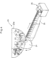
- a part feeder 23 of pivotal rail type for feeding the stock vials 8 and assay vials 21 has a vial storage 23a, and an inclined chute 25 disposed at a feeding end of pivotal rails 24 for transporting the stock vials 8 (assay vials 21) in line with the vials kept vertical as shown in Fig. 4.
- a vial separation device 26 At a downstream end of the inclined chute 25 is disposed a vial separation device 26.
- the vial separation device 26 allows the stock vials 8 (assay vials 21) sliding down along the inclined chute 25 to assume a predetermined attitude, and slightly upwardly projects the vial to facilitate the chucking of the vial by a chucking finger (which will be described later).
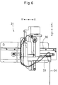
- a vial distributing/supplying device 30 as shown in Fig. 5 is disposed between the first turntable 14 and the second turntable 20, which includes a pivotally and vertically movable shaft 27, a swivel actuator 28 fixed at the top end of the shaft 27 and a chucking finger 29 attached at a free end of the swivel actuator 28.
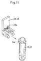
- the chucking finger 29 is adapted to resiliently hold a lip portion 8a of the stock vial 8 (assay vial 21) by the force of a spring 29a, as shown in Fig. 11.
- the swivel actuator 28 incorporates therein an air cylinder for projecting the chucking finger 29 in a direction indicated by arrow R to a position indicated by dotted line in Fig. 5.
- the vial distributing/supplying device 30 transports the stock vial 8 or assay vial 21 supplied by the vial separation device 26 into the vial retaining hole 15 of the first turntable 14 or the vial retaining hole 22 of the second turntable 20 by holding the lip portion of the stock vial 8 or assay vial 21 by means of the chucking finger 29. More specifically, when the swivel actuator 28 swivels counterclockwise from a vial chucking position of the vial separation device 26 (see Fig. 1), the stock vial 8 is supplied to the vial retaining hole 15 of the first turntable 14.
- the chucking finger 29 is designed so as to travel to positions above particular parts of the peripheral portions of the first and second turntables 14 and 20. That is, the chucking finger 29 is capable of traveling vertically as well as horizontally in an R-O direction within a horizontal plane including the aforesaid positions like a polar coordinates robot.
- second dispensing means 31 for aspirating part of a specimen in a stock vial 8 and dispensing the specimen to an assay vial 21.
- the second dispensing means 31 has an arm 33 movable in a vertical direction Z-Z', and a sampling probe 34 attached at a free end of the arm 33.
- the sampling probe 34 is connected to a constant-volume liquid transportation means 35 via a tube.
- the second dispensing means 31 is guided by guide rails 36 to travel in a direction Y-Y', so that the sampling probe 34 reciprocates between a vial retaining hole 15 in a predetermined position of the first turntable 14 and a vial retaining hole 22 in a predetermined position of the second turntable 20.
- a container of a diluent (not shown) is provided between the first turntable 14 and the second turntable 20.
- the sampling probe 34 Aspirates the diluent, so that a mixture of the specimen and the diluent is supplied in an assay vial 21.
- reagent dispensing means 37 for aspirating predetermined amounts of reagents in the reagent containers 16 and 17 and dispensing the reagents into the assay vial 21.
- the reagent dispensing means 37 has an arm 32 movable in a vertical direction Z-Z', and two sampling probes 38 and 39 attached at a free end of the arm 32.
- the sampling probes 38 and 39 are connected to constant-volume liquid transportation means 40 via tubes.
- the reagent dispensing means 37 is guided by guide rails 41 to travel in a direction Y-Y', so that the sampling probes 38 and 39 reciprocate between a reagent mixing position (below the sampling probe 38) of the chucking finger 29 (Fig. 5) and the reagent container retaining holes 18 and 19 in predetermined positions of the first turntable 14.
- Adjacent to the second turntable 20 are disposed four assay stages 42 for assaying specimens in assay vials 21, as shown in Fig. 1.
- the assay stages 42 are each formed with four assay holes 43 for accommodating the assay vials 21, and analysis means 52 for optically analyzing a specimen is provided near the bottom of each of the assay holes 43. More specifically, the characteristics of the specimen are determined by the measurement of scattered light intensity or transmittance, in which light is emitted to the specimen from the lateral side thereof.
- the assay stage 42 Above the assay stage 42 are provided two movable guide rails 44 and 45 horizontally extending in a direction X-X'.
- the movable guide rails 44 and 45 are movably attached on stationary guide rails 46 and 47 extending perpendicular to the movable guide rails 44 and 45 (in a direction Y-Y').
- On the movable guide rails 44 and 45 is mounted a vial transporting device 51 for vibrating the assay vial 21 at the reagent mixing position to mix the reagents with the specimen and transporting the assay vial 21 to a predetermined assay hole 43 of the assay stage 42.
- the vial transporting device 51 has a vertically movable chucking finger 48 which is the same type as the chucking finger 29 in the vial distributing/ supplying device 30.
- the chucking finger 48 is capable of traveling vertically in a direction Z-Z' as well as horizontally within a horizontal plane in directions X-X' and Y-Y' like an orthogonal coordinates robot, and stops at locations above a particular part of the peripheral portion of the second turntable 20, the reagent mixing position and the assay stage 42.
- a vibration motor (not shown) for vibrating the assay vial 21 to fully mix the reagents with the specimen in the assay vial 21.
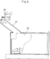
- a vial discharging chute 49 for discharging assay vials 21 after the assay is provided on a lower left side of the assay stages 42 as shown in Fig. 1.
- a used vial collecting box 50 for collecting used assay vials 21 after the assay is detachably attached to a lower end of the vial discharging chute 49 as shown in Fig. 8.
- Fig. 9 is a block diagram illustrating a control circuit in accordance with this embodiment.
- a controller 53 comprising a CPU, an ROM and an RAM includes a controlling section 53a for controlling the first dispensing means 9, a driver 14a for the first turntable 14, a driver 20a for the second turntable 20, the part feeder 23, the vial separation device 26, the vial distributing device 30, the second dispensing means 31, the reagent dispensing means 37, the vial transporting device 51 and assay means 52, and a judging section 53b for judging whether the assay is to be performed again on the same specimen based on an assay result and predetermined assay conditions.
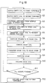
- the vial distributing/supplying device 30 successively supplies stock vials 8 into the vial retaining holes 15 of the first turntable 14 (Step S1).
- the vial distributing/supplying device 30 successively supplies assay vials 21 into the vial retaining holes 22 of the second turntable 20 after supplying the stock vials 8 (Step S2). Otherwise, the stock vials 8 and assay vials 21 may be alternately supplied.
- the first dispensing means 9 aspirates, for example, 100 ⁇ l to 500 ⁇ l of a specimen in each sample vial 4 and dispenses the specimen into a stock vial 8 in a vial retaining hole 15 (Step S3).
- the amount T of the specimen to be dispensed is determined on the basis of a volume necessary for one measurement (S1 + S2 + ... + Sn), the number (k) of measurements, and a spare volume (U) as previously stated.
- the dispensing of the specimens is controlled so that the sample vials 4 and the stock vials 8 have an exact one-to-one correspondence with each other.
- the second dispensing means 31 aspirates, for example, 5ul to 100ul of the specimen in the stock vial 8, then aspirates a predetermined amount of a diluent for dilution of the specimen if necessary, and dispenses the diluted specimen into the assay vial 21 (Step S4). Accordingly, a certain amount of the specimen remains in the stock vial 8.
- the chucking finger 4 holds the assay vial 21 containing the diluted specimen and transports the assay vial 21 from the vial retaining hole 22 of the second turntable 20 to the reagent mixing position (Step S5).
- the reagent dispensing means 37 aspirates a predetermined reagent, then travels to the reagent mixing position, and dispenses the reagent into the assay vial 21 (Step S6).
- the vibration motor vibrates the chucking finger 48 holding the assay vial 21 to fully mix the reagent with the specimen in the assay vial 21 (Step S7).
- the assay vial 21 is inserted into a predetermined assay hole 43 and the specimen is subjected to an assay (Steps S8 and S9).
- the time required for an assay varies depending on the assay category and, typically, is three minutes to ten minutes.
- the reagent dispensing means 37 has two sampling probes 38 and 39, which are selectively used depending on the kind of reagent to be used and the assay category.
- the used assay vial 21 is transported to the vial discharging chute 49 by means of the chucking finger 48 and collected into the used vial collecting box 50 (Step S10). If a plurality of assays such as for PT and APTT are to be performed or a reflex test is to be performed (step S11), the judging section 53b causes the process sequence after the dispensing of the specimen by the second dispensing means 31 (Steps S4 to S10) to be repeated predetermined times. In such a case, different kinds of reagents may be used in different amounts, depending on the assay to be performed.
- Step S11 judges in Step S11 that the assay result on the specimen is within a predetermined abnormal value range or out of a predetermined normal value range (or the specimen has to be re-assayed)
- the first turntable 14 is rotated and the stock vial 8 containing the specimen is automatically selected.
- the specimen is assayed again by following the aforesaid process sequence. That is, the specimen is dispensed into an assay vial 21, then the reagent is added thereto, and the assay is performed again on the specimen.
- the vial distributing/supplying device 30 temporality transfers the stock vials 8 on the first turntable 14 into the vial retaining holes 22 of the second turntable 20. Then, the chucking finger 48 transfers the stock vials 8 from the second turntable 20 to the used vial collecting box 50 (Step S12).
- the amount of the diluent to be dispensed can be properly adjusted. More specifically, when the assay result is out of an effective accuracy range due to a high or low concentration of the specimen, the dilution may be increased or decreased so as to adjust the concentration of the specimen for the re-assay.
- the stock vials 8 are cooled to a temperature of 15°C as described above. Therefore, the specimens will not evaporate even if the specimen is left in the vial 8 for a long time before the assay.
- a specimen in a stock vial can be used for plural measurements or plural assays by dispensing the specimen from the stock vial into an assay vial plural times. Even if a sample vial containing the specimen is transported to the next process, the re-assay of the specimen can be easily performed. This realizes a more effective re-assay.
- the apparatus of the present invention has a simpler and smaller-scale construction, and thereby less costly, in comparison with an analyzer adapted to return a rack accommodating a necessary sample vial thereto every time a re-assay is to be performed.
Landscapes
- Chemical & Material Sciences (AREA)
- Biochemistry (AREA)
- General Physics & Mathematics (AREA)
- Health & Medical Sciences (AREA)
- Life Sciences & Earth Sciences (AREA)
- Analytical Chemistry (AREA)
- Quality & Reliability (AREA)
- General Health & Medical Sciences (AREA)
- Physics & Mathematics (AREA)
- Immunology (AREA)
- Pathology (AREA)
- Engineering & Computer Science (AREA)
- Chemical Kinetics & Catalysis (AREA)
- Automatic Analysis And Handling Materials Therefor (AREA)
- Specific Conveyance Elements (AREA)
Applications Claiming Priority (3)
| Application Number | Priority Date | Filing Date | Title |
|---|---|---|---|
| JP26601594A JP3229498B2 (ja) | 1994-09-21 | 1994-09-21 | 検体の自動分析方法および装置 |
| JP266015/94 | 1994-09-21 | ||
| JP26601594 | 1994-09-21 |
Publications (3)
| Publication Number | Publication Date |
|---|---|
| EP0703456A2 true EP0703456A2 (fr) | 1996-03-27 |
| EP0703456A3 EP0703456A3 (fr) | 1996-12-11 |
| EP0703456B1 EP0703456B1 (fr) | 2003-08-13 |
Family
ID=17425197
Family Applications (1)
| Application Number | Title | Priority Date | Filing Date |
|---|---|---|---|
| EP95402117A Expired - Lifetime EP0703456B1 (fr) | 1994-09-21 | 1995-09-20 | Méthode et dispositif pour l'analyse automatique d'un échantillon |
Country Status (4)
| Country | Link |
|---|---|
| US (1) | US5587129A (fr) |
| EP (1) | EP0703456B1 (fr) |
| JP (1) | JP3229498B2 (fr) |
| DE (1) | DE69531475T2 (fr) |
Cited By (12)
| Publication number | Priority date | Publication date | Assignee | Title |
|---|---|---|---|---|
| WO2001035069A1 (fr) * | 1999-11-09 | 2001-05-17 | Biopsytec Gmbh | Procede et dispositif permettant la preparation d'echantillons biologiques pour une analyse d'adn |
| WO2002044739A3 (fr) * | 2000-11-30 | 2004-01-08 | Dade Behring Inc | Methode permettant de stocker et de traiter a nouveau automatiquement un prelevement d'un patient dans un analyseur clinique automatique |
| EP1741489A1 (fr) * | 2003-08-22 | 2007-01-10 | Sysmex Corporation | Récipient de réaction pour l'analyse |
| CN102216784A (zh) * | 2008-11-17 | 2011-10-12 | 株式会社日立高新技术 | 自动分析装置 |
| JP2015514223A (ja) * | 2012-04-13 | 2015-05-18 | ベクトン・ディキンソン・アンド・カンパニーBecton, Dickinson And Company | 前試験からの残留物質を使用してのサンプルの反射試験 |
| EP2259069A4 (fr) * | 2008-03-31 | 2016-05-25 | Sysmex Corp | Appareil d'analyse de la coagulation du sang, procédé d'analyse de la coagulation du sang et programme informatique |
| CN103941027B (zh) * | 2005-03-29 | 2016-09-07 | 希森美康株式会社 | 标本分析方法及标本分析装置 |
| EP3100698A1 (fr) * | 2015-05-28 | 2016-12-07 | Siemens Healthcare Diagnostics Products GmbH | Systeme de transfert de dechets |
| CN108333178A (zh) * | 2018-02-07 | 2018-07-27 | 爱威科技股份有限公司 | 临床标本分析方法及临床标本分析仪 |
| EP3825698A1 (fr) * | 2014-06-11 | 2021-05-26 | F. Hoffmann-La Roche AG | Procédé et système d'analyse de diagnostic in vitro |
| WO2021147183A1 (fr) * | 2020-01-21 | 2021-07-29 | 深圳迎凯生物科技有限公司 | Appareil d'analyse |
| CN114560290A (zh) * | 2022-03-11 | 2022-05-31 | 山东亚历山大智能科技有限公司 | 一种基于坩埚架协同控制的纤维质量检测系统及方法 |
Families Citing this family (49)
| Publication number | Priority date | Publication date | Assignee | Title |
|---|---|---|---|---|
| JP3229915B2 (ja) * | 1995-01-19 | 2001-11-19 | 日本電子株式会社 | 生化学自動分析装置 |
| JP3582240B2 (ja) * | 1996-06-14 | 2004-10-27 | 東ソー株式会社 | 自動検体前処理装置および自動検体前処理方法 |
| US8337753B2 (en) | 1998-05-01 | 2012-12-25 | Gen-Probe Incorporated | Temperature-controlled incubator having a receptacle mixing mechanism |
| ES2286750T3 (es) | 1998-05-01 | 2007-12-01 | Gen-Probe Incorporated | Dispositivo para agitar el contenido liquido de un contenedor. |
| JP4451539B2 (ja) * | 1999-05-11 | 2010-04-14 | シスメックス株式会社 | 自動分析装置および自動分析装置用容器供給装置 |
| US6919044B1 (en) * | 1999-06-17 | 2005-07-19 | Beckman Coulter, Inc. | Sample loading and handling interface to multiple chemistry analyzers |
| WO2001028680A2 (fr) * | 1999-10-20 | 2001-04-26 | Gentra Systems, Inc. | Appareil a melanger et a verser et recipient correspondant |
| US6825041B2 (en) | 2001-03-16 | 2004-11-30 | Beckman Coulter, Inc. | Method and system for automated immunochemistry analysis |
| EP1436586A2 (fr) | 2001-10-19 | 2004-07-14 | MonoGen, Inc. | Systeme et procede automatises de traitement d'echantillons multiples a base de liquide |
| AU2003241450A1 (en) * | 2002-05-13 | 2003-12-02 | Scinomix | Automated processing system and method of using same |
| US7501094B2 (en) * | 2003-09-15 | 2009-03-10 | Syngenta Limited | Preparation and characterization of formulations in a high throughput mode |
| US7964413B2 (en) | 2005-03-10 | 2011-06-21 | Gen-Probe Incorporated | Method for continuous mode processing of multiple reaction receptacles in a real-time amplification assay |
| JP4881855B2 (ja) | 2005-03-29 | 2012-02-22 | シスメックス株式会社 | 検体分析方法および検体分析装置 |
| USD531736S1 (en) | 2005-05-04 | 2006-11-07 | Abbott Laboratories | Reagent carrier for use in an automated analyzer |
| USD534280S1 (en) | 2005-05-04 | 2006-12-26 | Abbott Laboratories | Reagent carrier for use in an automated analyzer |
| USD532524S1 (en) | 2005-05-04 | 2006-11-21 | Abbott Laboratories | Reagent carrier for use in an automated analyzer |
| USD533947S1 (en) | 2005-05-04 | 2006-12-19 | Abbott Laboratories | Reagent carrier for use in an automated analyzer |
| US7628954B2 (en) * | 2005-05-04 | 2009-12-08 | Abbott Laboratories, Inc. | Reagent and sample handling device for automatic testing system |
| WO2007013254A1 (fr) * | 2005-07-27 | 2007-02-01 | Sysmex Corporation | Cuvette |
| US20070172390A1 (en) * | 2006-01-23 | 2007-07-26 | Sysmex Corporation | Analyzing apparatus, solid-liquid separation device and solid-liquid separation method |
| JP4890070B2 (ja) * | 2006-03-31 | 2012-03-07 | シスメックス株式会社 | 分析装置 |
| JP4875391B2 (ja) | 2006-03-30 | 2012-02-15 | シスメックス株式会社 | 検体分析装置 |
| US7855077B2 (en) * | 2006-09-29 | 2010-12-21 | Beckman Coulter, Inc. | Method and device for test sample loading |
| WO2008092116A2 (fr) * | 2007-01-26 | 2008-07-31 | Biodot, Inc. | Procédé et appareil d'échantillonnage de poudre solide à distribution directe sans contact |
| JP5108366B2 (ja) * | 2007-03-29 | 2012-12-26 | シスメックス株式会社 | 検体分析装置 |
| JP5431755B2 (ja) | 2008-10-31 | 2014-03-05 | シスメックス株式会社 | 検体分析装置および検体分析方法 |
| JP5726993B2 (ja) * | 2008-10-31 | 2015-06-03 | シスメックス株式会社 | 検体分析装置および検体分析方法 |
| JP5300447B2 (ja) * | 2008-12-04 | 2013-09-25 | ベックマン コールター, インコーポレイテッド | 自動分析装置および自動分析装置における検体分注方法 |
| JP5452070B2 (ja) * | 2009-04-28 | 2014-03-26 | 株式会社日立ハイテクノロジーズ | 自動分析装置 |
| US9046507B2 (en) | 2010-07-29 | 2015-06-02 | Gen-Probe Incorporated | Method, system and apparatus for incorporating capacitive proximity sensing in an automated fluid transfer procedure |
| JP5727219B2 (ja) | 2010-12-28 | 2015-06-03 | シスメックス株式会社 | 検体分析装置及び検体分析システム |
| AU2012222178B2 (en) | 2011-02-24 | 2014-12-18 | Gen-Probe Incorporated | Systems and methods for distinguishing optical signals of different modulation frequencies in an optical signal detector |
| HU228711B1 (en) | 2011-08-22 | 2013-05-28 | Diagon Kft | Method and apparatus for feeding cuvetta comprising assay and reagent |
| JP5923270B2 (ja) * | 2011-10-07 | 2016-05-24 | 株式会社日立ハイテクノロジーズ | 検体処理システム |
| JP6072450B2 (ja) * | 2012-07-12 | 2017-02-01 | 株式会社日立ハイテクノロジーズ | 自動分析装置 |
| EP2698624A1 (fr) * | 2012-08-16 | 2014-02-19 | Siemens Healthcare Diagnostics Products GmbH | Récipient réactionnel |
| EP3964839B1 (fr) | 2013-03-15 | 2024-04-10 | Abbott Laboratories | Analyseurs diagnostiques automatiques comprenant des systèmes de rail accessibles par l'arrière et procédés associés |
| CN105190317B (zh) | 2013-03-15 | 2018-05-04 | 雅培制药有限公司 | 具有预处理转盘的诊断分析机及相关方法 |
| CN109358202B (zh) | 2013-03-15 | 2023-04-07 | 雅培制药有限公司 | 具有竖直布置的圆盘传送带的自动化诊断分析仪及相关方法 |
| CN105572407B (zh) * | 2016-01-27 | 2018-01-16 | 广州万孚生物技术股份有限公司 | 全自动荧光定量免疫分析仪及检测方法 |
| US10192637B2 (en) * | 2017-05-31 | 2019-01-29 | Sysmex Corporation | Specimen analyzer and specimen analysis method |
| CN111712452B (zh) * | 2018-02-23 | 2022-06-14 | 美国西门子医学诊断股份有限公司 | 临床分析仪和用于运输样品池的方法 |
| JP7134747B2 (ja) * | 2018-06-29 | 2022-09-12 | キヤノンメディカルシステムズ株式会社 | キュベット搬送装置及び自動分析装置 |
| CN111521773B (zh) * | 2019-02-02 | 2021-09-14 | 深圳迎凯生物科技有限公司 | 液体分配方法和免疫分析方法 |
| CN111521772B (zh) * | 2019-02-02 | 2021-12-07 | 深圳迎凯生物科技有限公司 | 液体分配方法和免疫分析方法 |
| EP3699598A1 (fr) * | 2019-02-25 | 2020-08-26 | Siemens Healthcare Diagnostics Products GmbH | Système de transfert de déchets |
| CN113125774A (zh) * | 2019-12-31 | 2021-07-16 | 科美诊断技术股份有限公司 | 测试方法及装置 |
| JP2021135295A (ja) * | 2020-02-21 | 2021-09-13 | キヤノンメディカルシステムズ株式会社 | 自動分析装置 |
| CN116194782B (zh) * | 2020-10-20 | 2026-01-13 | 株式会社日立高新技术 | 自动分析装置 |
Family Cites Families (16)
| Publication number | Priority date | Publication date | Assignee | Title |
|---|---|---|---|---|
| US4478095A (en) * | 1981-03-09 | 1984-10-23 | Spectra-Physics, Inc. | Autosampler mechanism |
| JPS5985959A (ja) * | 1982-11-09 | 1984-05-18 | Nippon Tectron Co Ltd | 自動分析装置 |
| US4965049A (en) * | 1986-07-11 | 1990-10-23 | Beckman Instruments, Inc. | Modular analyzer system |
| JPS63229369A (ja) * | 1987-03-18 | 1988-09-26 | Toshiba Corp | 生化学自動分析装置 |
| JPS63243880A (ja) * | 1987-03-31 | 1988-10-11 | Shimadzu Corp | 自動分析装置 |
| JPS6443761A (en) * | 1987-08-11 | 1989-02-16 | Shimadzu Corp | Automatic analysis apparatus |
| JPH06103315B2 (ja) * | 1987-08-14 | 1994-12-14 | 株式会社東芝 | 自動化学分析装置の分注ノズル装置 |
| US5051238A (en) * | 1987-11-20 | 1991-09-24 | Hitachi, Ltd. | Automatic analyzing system |
| JPH01187461A (ja) * | 1988-01-22 | 1989-07-26 | Toshiba Corp | 自動化学分析装置 |
| JP2649409B2 (ja) * | 1989-03-14 | 1997-09-03 | 株式会社日立製作所 | 臨床検査用の自動分析方法 |
| US5183638A (en) * | 1989-12-04 | 1993-02-02 | Kabushiki Kaisha Nittec | Automatic immunity analysis apparatus with magnetic particle separation |
| GB9020352D0 (en) * | 1990-09-18 | 1990-10-31 | Anagen Ltd | Assay or reaction apparatus |
| DE69208757T2 (de) * | 1991-07-16 | 1997-02-06 | Kodak Ag | Vorrichtung zum Zuführen von Gegenständen zu einem Müllbehälter eines Analysators |
| JP2761611B2 (ja) * | 1992-02-22 | 1998-06-04 | 株式会社堀場製作所 | 分析用の前処理装置 |
| US5376313A (en) * | 1992-03-27 | 1994-12-27 | Abbott Laboratories | Injection molding a plastic assay cuvette having low birefringence |
| JP2842758B2 (ja) * | 1993-05-10 | 1999-01-06 | 株式会社日立製作所 | 自動分析装置 |
-
1994
- 1994-09-21 JP JP26601594A patent/JP3229498B2/ja not_active Expired - Fee Related
-
1995
- 1995-09-20 US US08/530,901 patent/US5587129A/en not_active Expired - Lifetime
- 1995-09-20 EP EP95402117A patent/EP0703456B1/fr not_active Expired - Lifetime
- 1995-09-20 DE DE69531475T patent/DE69531475T2/de not_active Expired - Lifetime
Non-Patent Citations (1)
| Title |
|---|
| None |
Cited By (16)
| Publication number | Priority date | Publication date | Assignee | Title |
|---|---|---|---|---|
| WO2001035069A1 (fr) * | 1999-11-09 | 2001-05-17 | Biopsytec Gmbh | Procede et dispositif permettant la preparation d'echantillons biologiques pour une analyse d'adn |
| WO2002044739A3 (fr) * | 2000-11-30 | 2004-01-08 | Dade Behring Inc | Methode permettant de stocker et de traiter a nouveau automatiquement un prelevement d'un patient dans un analyseur clinique automatique |
| EP1741489A1 (fr) * | 2003-08-22 | 2007-01-10 | Sysmex Corporation | Récipient de réaction pour l'analyse |
| CN103941027B (zh) * | 2005-03-29 | 2016-09-07 | 希森美康株式会社 | 标本分析方法及标本分析装置 |
| EP3432002A1 (fr) * | 2008-03-31 | 2019-01-23 | Sysmex Corporation | Analyseur de la coagulation du sang, procédé d'analyse de la coagulation du sang et programme informatique |
| EP2259069A4 (fr) * | 2008-03-31 | 2016-05-25 | Sysmex Corp | Appareil d'analyse de la coagulation du sang, procédé d'analyse de la coagulation du sang et programme informatique |
| CN102216784A (zh) * | 2008-11-17 | 2011-10-12 | 株式会社日立高新技术 | 自动分析装置 |
| CN102216784B (zh) * | 2008-11-17 | 2014-07-09 | 株式会社日立高新技术 | 自动分析装置 |
| JP2015514223A (ja) * | 2012-04-13 | 2015-05-18 | ベクトン・ディキンソン・アンド・カンパニーBecton, Dickinson And Company | 前試験からの残留物質を使用してのサンプルの反射試験 |
| EP3825698A1 (fr) * | 2014-06-11 | 2021-05-26 | F. Hoffmann-La Roche AG | Procédé et système d'analyse de diagnostic in vitro |
| EP3825697A1 (fr) * | 2014-06-11 | 2021-05-26 | F. Hoffmann-La Roche AG | Procédé et système d'analyse de diagnostic in vitro |
| EP3168620A1 (fr) * | 2015-05-28 | 2017-05-17 | Siemens Healthcare Diagnostics Products GmbH | Systeme de transfert de dechets |
| EP3100698A1 (fr) * | 2015-05-28 | 2016-12-07 | Siemens Healthcare Diagnostics Products GmbH | Systeme de transfert de dechets |
| CN108333178A (zh) * | 2018-02-07 | 2018-07-27 | 爱威科技股份有限公司 | 临床标本分析方法及临床标本分析仪 |
| WO2021147183A1 (fr) * | 2020-01-21 | 2021-07-29 | 深圳迎凯生物科技有限公司 | Appareil d'analyse |
| CN114560290A (zh) * | 2022-03-11 | 2022-05-31 | 山东亚历山大智能科技有限公司 | 一种基于坩埚架协同控制的纤维质量检测系统及方法 |
Also Published As
| Publication number | Publication date |
|---|---|
| EP0703456A3 (fr) | 1996-12-11 |
| JPH0894636A (ja) | 1996-04-12 |
| EP0703456B1 (fr) | 2003-08-13 |
| JP3229498B2 (ja) | 2001-11-19 |
| US5587129A (en) | 1996-12-24 |
| DE69531475D1 (de) | 2003-09-18 |
| DE69531475T2 (de) | 2004-07-01 |
Similar Documents
| Publication | Publication Date | Title |
|---|---|---|
| EP0703456B1 (fr) | Méthode et dispositif pour l'analyse automatique d'un échantillon | |
| EP0431578B1 (fr) | Procédé de vérification de la précision d'un distributeur de liquide | |
| US6984527B2 (en) | Automated quality control protocols in a multi-analyzer system | |
| US6579717B1 (en) | Specific solution handling method for calibration and quality control by automatic analytical apparatus | |
| US5270210A (en) | Capacitive sensing system and wash/alignment station for a chemical analyzer | |
| JP6653375B2 (ja) | 自動分析装置 | |
| US7185288B2 (en) | Operator interface module segmented by function in an automatic clinical analyzer | |
| JP3428426B2 (ja) | 検体分析システム | |
| EP1087231B1 (fr) | Appareil automatique d'analyse | |
| JP2007537448A (ja) | 自動臨床アナライザで用いる較正溶液システム | |
| EP2073934A1 (fr) | Adaptateur pour portoir de récipient à micro-échantillons | |
| WO2007139212A1 (fr) | Analyseur automatique | |
| JP2004271265A (ja) | 自動分析装置 | |
| CN112924706B (zh) | 用于封闭液体容器的移液单元和移液方法 | |
| JPH01187461A (ja) | 自動化学分析装置 | |
| KR20060058682A (ko) | 모듈형 시약 전달 수단을 이용한 자동 임상 분석기의 용량증가 방법 | |
| EP2072999A1 (fr) | Procédé d'identification d'anomalie et appareil d'analyse | |
| JP2611609B2 (ja) | 臨床用複合分析装置 | |
| EP0170494A2 (fr) | Criblage de veaux | |
| JPH06281656A (ja) | 分析装置 | |
| JP2590688Y2 (ja) | 血液凝固分析装置 | |
| JPS6249259A (ja) | 自動分析装置 | |
| JPH047956B2 (fr) | ||
| JPH06288916A (ja) | 生化学分析方法 | |
| JP2892678B2 (ja) | 自動分析装置 |
Legal Events
| Date | Code | Title | Description |
|---|---|---|---|
| PUAI | Public reference made under article 153(3) epc to a published international application that has entered the european phase |
Free format text: ORIGINAL CODE: 0009012 |
|
| AK | Designated contracting states |
Kind code of ref document: A2 Designated state(s): DE FR |
|
| PUAL | Search report despatched |
Free format text: ORIGINAL CODE: 0009013 |
|
| AK | Designated contracting states |
Kind code of ref document: A3 Designated state(s): DE FR |
|
| 17P | Request for examination filed |
Effective date: 19970515 |
|
| RAP1 | Party data changed (applicant data changed or rights of an application transferred) |
Owner name: SYSMEX CORPORATION |
|
| 17Q | First examination report despatched |
Effective date: 20010723 |
|
| GRAH | Despatch of communication of intention to grant a patent |
Free format text: ORIGINAL CODE: EPIDOS IGRA |
|
| GRAH | Despatch of communication of intention to grant a patent |
Free format text: ORIGINAL CODE: EPIDOS IGRA |
|
| GRAA | (expected) grant |
Free format text: ORIGINAL CODE: 0009210 |
|
| AK | Designated contracting states |
Designated state(s): DE FR |
|
| REF | Corresponds to: |
Ref document number: 69531475 Country of ref document: DE Date of ref document: 20030918 Kind code of ref document: P |
|
| ET | Fr: translation filed | ||
| PLBE | No opposition filed within time limit |
Free format text: ORIGINAL CODE: 0009261 |
|
| STAA | Information on the status of an ep patent application or granted ep patent |
Free format text: STATUS: NO OPPOSITION FILED WITHIN TIME LIMIT |
|
| 26N | No opposition filed |
Effective date: 20040514 |
|
| PGFP | Annual fee paid to national office [announced via postgrant information from national office to epo] |
Ref country code: DE Payment date: 20140917 Year of fee payment: 20 |
|
| PGFP | Annual fee paid to national office [announced via postgrant information from national office to epo] |
Ref country code: FR Payment date: 20140906 Year of fee payment: 20 |
|
| REG | Reference to a national code |
Ref country code: DE Ref legal event code: R071 Ref document number: 69531475 Country of ref document: DE |