EP0703467A1 - Tête d'émission-réception pour anémomètre doppler longitudinal - Google Patents
Tête d'émission-réception pour anémomètre doppler longitudinal Download PDFInfo
- Publication number
- EP0703467A1 EP0703467A1 EP95402118A EP95402118A EP0703467A1 EP 0703467 A1 EP0703467 A1 EP 0703467A1 EP 95402118 A EP95402118 A EP 95402118A EP 95402118 A EP95402118 A EP 95402118A EP 0703467 A1 EP0703467 A1 EP 0703467A1
- Authority
- EP
- European Patent Office
- Prior art keywords
- polarization
- head according
- switching
- switching means
- alternately
- Prior art date
- Legal status (The legal status is an assumption and is not a legal conclusion. Google has not performed a legal analysis and makes no representation as to the accuracy of the status listed.)
- Granted
Links
Images

Classifications
-
- G—PHYSICS
- G01—MEASURING; TESTING
- G01S—RADIO DIRECTION-FINDING; RADIO NAVIGATION; DETERMINING DISTANCE OR VELOCITY BY USE OF RADIO WAVES; LOCATING OR PRESENCE-DETECTING BY USE OF THE REFLECTION OR RERADIATION OF RADIO WAVES; ANALOGOUS ARRANGEMENTS USING OTHER WAVES
- G01S7/00—Details of systems according to groups G01S13/00, G01S15/00, G01S17/00
- G01S7/48—Details of systems according to groups G01S13/00, G01S15/00, G01S17/00 of systems according to group G01S17/00
- G01S7/499—Details of systems according to groups G01S13/00, G01S15/00, G01S17/00 of systems according to group G01S17/00 using polarisation effects
-
- G—PHYSICS
- G01—MEASURING; TESTING
- G01S—RADIO DIRECTION-FINDING; RADIO NAVIGATION; DETERMINING DISTANCE OR VELOCITY BY USE OF RADIO WAVES; LOCATING OR PRESENCE-DETECTING BY USE OF THE REFLECTION OR RERADIATION OF RADIO WAVES; ANALOGOUS ARRANGEMENTS USING OTHER WAVES
- G01S17/00—Systems using the reflection or reradiation of electromagnetic waves other than radio waves, e.g. lidar systems
- G01S17/02—Systems using the reflection of electromagnetic waves other than radio waves
- G01S17/50—Systems of measurement based on relative movement of target
- G01S17/58—Velocity or trajectory determination systems; Sense-of-movement determination systems
-
- Y—GENERAL TAGGING OF NEW TECHNOLOGICAL DEVELOPMENTS; GENERAL TAGGING OF CROSS-SECTIONAL TECHNOLOGIES SPANNING OVER SEVERAL SECTIONS OF THE IPC; TECHNICAL SUBJECTS COVERED BY FORMER USPC CROSS-REFERENCE ART COLLECTIONS [XRACs] AND DIGESTS
- Y02—TECHNOLOGIES OR APPLICATIONS FOR MITIGATION OR ADAPTATION AGAINST CLIMATE CHANGE
- Y02A—TECHNOLOGIES FOR ADAPTATION TO CLIMATE CHANGE
- Y02A90/00—Technologies having an indirect contribution to adaptation to climate change
- Y02A90/10—Information and communication technologies [ICT] supporting adaptation to climate change, e.g. for weather forecasting or climate simulation
Definitions
- the present invention relates to a transmission-reception head for a longitudinal Doppler anemometer, and more particularly for such an anemometer with at least one pair of measurement axes.
- Doppler anemometry techniques are already known in which a laser beam of frequency f is emitted from a vehicle, in particular an aircraft, in motion relative to the ambient air.
- the light backscattered by the aerosols suspended in the air is received, and the Doppler shift ⁇ f of the frequency of the backscattered light is measured relative to the frequency f.
- the Doppler shift ⁇ f is proportional to the projection of the vehicle speed on the measurement axis.
- the speed vector can be determined by carrying out three measurements on three different measurement axes.
- four measurement axes will preferably be chosen in order to have redundant information.
- the invention aims to provide a transmission-reception head for an anemometer having the above characteristics and which, moreover, preferably does not include moving mechanical parts, the vibrations of which would be harmful both to the reliability of the equipment. than the accuracy of the measurement.
- a single laser is used in the transmission-reception head according to the invention, and its power is alternately switched on one and the other of the axes of a pair of measurement axes.
- the separating means can for example be produced from a Glan prism.
- the polarization switching means can be produced from electro-optical effect means such as, for example, a Pockels effect cell, a nematic or ferroelectric liquid crystal, or a ZnSe crystal. elasto-optical effect.
- the transmission-reception head according to the invention therefore makes it possible to achieve the desired objectives without mechanical means.
- the separating means are arranged so that the beam which results therefrom is displaced parallel to itself during switching, an output optic being arranged to direct the beam on one of the measurement axes in depending on its displacement.
- a quarter-wave plate is advantageously arranged at the output of the polarization separating means.
- this strip is to transform the linearly polarized beam into a circularly polarized beam. Aerosols having a generally spherical shape, the polarization of the backscattered beam is reversed circular. After the quarter-wave plate, the backscattered beam is therefore linearly polarized, but 90 ° from the input beam. It therefore always emerges in the same direction of polarization separating means and can be collected at this level by suitable means, for example by an optical fiber.
- the output optics of the transmission-reception head according to the invention consists of a telescope.
- the transmission-reception head shown in FIG. 1 comprises a laser 1, the beam of which is returned by mirrors 2 and 3 to polarization switching means 4, for example with liquid crystal Control means 5 switch means 4 so that the beam 6 which results therefrom alternately has linear polarizations offset by 90 °.
- the beam 6 is then divided into two parallel beams in a prism 7 and, at the outlet of the prism 7, the two beams thus obtained pass through the polarization splitter 8 which will now be described with reference to FIGS. 2 to 6.
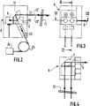
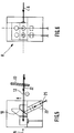
- the separator 8 is formed by a Glan prism 9, the active face 10 of which is crossed by the two beams ( Figures 5 and 6), or reflects them towards a mirror 11 ( Figures 2 and 3), according to their polarization state .
- the face 10 of the Glan prism and the mirror 11 are parallel, so that the exit beams of the separator 8, i.e. either the two crossing beams 12 or the two twice-reflected beams 12 ′, are parallel .
- the large mirror 16 of the telescope 15 comprises only four elementary mirrors, one for each beam coming from the polarization splitter 8. Furthermore, the light beams are folded back inside the telescope by two sets of four plane mirrors 20 and 21, which makes it possible to reduce the length of the device.
- the light backscattered by aerosols from the air, and whose circular polarization is therefore reversed, is recollected by the telescope 15, after which it crosses back the quarter-wave plate 13.
- the backscattered beams 22 and 22 'respectively , penetrating into the polarization splitter 8, are therefore linearly polarized, but with a shift of 90 ° relative to the incident beams.
- the beam 22 coming from the beam 12 having passed through the face 10 of the Glan prism is reflected by this same face (FIG. 5).
- the beam 22 'coming from the beam 12' having been reflected by the face 10 passes through this face (FIG. 2).
- All the backscattered beams are therefore returned to a collimating optic 23 and, from there, to an analyzer 24, via an optical fiber 25.
- the optical fiber 25 is preferably a polarization-conserving fiber, so to allow coherent detection (using a local oscillator) at the level of the analyzer 24.
- the control means 5 switch the polarization switching means 4 alternately from one state to another.
- the polarization splitter 8 alternately allows the beams 12 and 12 ′ to pass, which has the effect of allowing the analyzer 24 to process two measurement axes alternately then the other two axes.
Landscapes
- Physics & Mathematics (AREA)
- Engineering & Computer Science (AREA)
- Electromagnetism (AREA)
- Computer Networks & Wireless Communication (AREA)
- General Physics & Mathematics (AREA)
- Radar, Positioning & Navigation (AREA)
- Remote Sensing (AREA)
- Optical Radar Systems And Details Thereof (AREA)
Abstract
Description
- La présente invention concerne une tête d'émission-réception pour anémomètre Doppler longitudinal, et plus particulièrement pour un tel anémomètre à au moins une paire d'axes de mesure.
- On connaît déjà des techniques d'anémométrie Doppler longitudinale dans lesquelles on émet un faisceau laser de fréquence f à partir d'un véhicule, notamment un aéronef, en mouvement par rapport à l'air ambiant. On reçoit la lumière rétrodiffusée par les aérosols en suspension dans l'air, et on mesure le décalage Doppler Δf de la fréquence de la lumière rétrodiffusée par rapport à la fréquence f. On sait que le décalage Doppler Δf est proportionnel à la projection de la vitesse du véhicule sur l'axe de mesure.
- Par conséquent, on peut déterminer le vecteur vitesse en effectuant trois mesures sur trois axes de mesure différents. En fait, on choisira de préférence quatre axes de mesure afin de disposer d'une information redondante.
- Par ailleurs, il est souhaitable, tant pour des raisons de poids que de coût, de former tous les faisceaux à partir d'un laser unique. Il faut donc pouvoir diviser le faisceau émis par le laser de manière à le diriger sur les différents axes de mesure choisis. Il est également souhaitable de ne pas diriger le faisceau simultanément sur tous les axes de mesure, afin de bénéficier d'une puissance plus importante pour chaque mesure.
- L'invention vise à fournir une tête d'émission-réception pour un anémomètre présentant les caractéristiques précitées et qui, de plus, de préférence, ne comporte pas de pièces mécaniques en mouvement, dont les vibrations seraient nuisibles aussi bien à la fiabilité du matériel qu'à la précision de la mesure.
- A cet effet, l'invention a pour objet une tête d'émission-réception pour anémomètre laser longitudinal à au moins une paire d'axes de mesure, caractérisée par le fait qu'elle comprend:
- un laser;
- des moyens de commutation de polarisation sur le trajet du faisceau laser;
- des moyens séparateurs de polarisation sur le trajet du faisceau polarisé issu des moyens de commutation;
- des moyens de commande pour commuter les moyens de commutation alternativement d'un état à un autre de manière à diriger le faisceau alternativement sur un axe de mesure puis sur un autre en fonction de son état de polarisation.
- Ainsi, un seul laser est utilisé dans la tête d'émission-réception selon l'invention, et sa puissance est alternativement commutée sur l'un et l'autre des axes d'une paire d'axes de mesure.
- Les moyens séparateurs peuvent par exemple être réalisés à partir d'un prisme de Glan. De même, les moyens de commutation de polarisation peuvent être réalisés à partir de moyens à effet électro-optique tels, par exemple, qu'une cellule à effet Pockels, qu'un cristal liquide nématique ou ferroélectrique, ou qu'un cristal de ZnSe à effet élasto-optique. La tête d'émission-réception selon l'invention permet par conséquent d'atteindre les objectifs recherchés sans moyens mécaniques.
- Dans un mode de réalisation particulier, les moyens séparateurs sont agencés de sorte que le faisceau qui en est issu est déplacé parallèlement à lui-même lors de la commutation, une optique de sortie étant agencée pour diriger le faisceau sur un des axes de mesure en fonction de son déplacement.
- Une lame quart d'onde est avantageusement disposée à la sortie des moyens séparateurs de polarisation.
- Cette lame a pour effet de transformer le faisceau polarisé linéairement en un faisceau polarisé circulairement. Les aérosols ayant une forme généralement sphérique, la polarisation du faisceau rétrodiffusé est circulaire inversée. Après la lame quart d'onde, le faisceau rétrodiffusé est donc polarisé linéairement, mais à 90° du faisceau d'entrée. Il ressort donc toujours dans la même direction des moyens séparateurs de polarisation et peut être collecté à ce niveau par des moyens appropriés, par exemple par une fibre optique.
- Egalement dans un mode de réalisation particulier, l'optique de sortie de la tête d'émission-réception selon l'invention est constituée d'un télescope.
- On décrira maintenant, à titre d'exemple non limitatif, un mode de réalisation particulier de l'invention, en référence aux dessins annexés dans lesquels:
- la figure 1 est une vue en coupe d'une tête d'émission-réception selon l'invention, pour un anémomètre à quatre axes de mesure;
- la figure 2 est une vue en coupe des moyens séparateurs de polarisation représentés à la figure 1, selon la ligne II-II de la figure 3;
- la figure 3 est une vue de face des moyens séparateurs de polarisation;
- la figure 4 est une vue en coupe selon la ligne IV-IV de la figure 3; et
- les figures 5 et 6 sont des figures analogues aux figures 2 et 3 pour une autre polarisation du faisceau d'entrée.
- La tête d'émission-réception représentée à la figure 1 comprend un laser 1 dont le faisceau est renvoyé par des miroirs 2 et 3 à des moyens de commutation de polarisation 4, par exemple à cristaux liquides Des moyens de commande 5 commutent les moyens 4 de manière que le faisceau 6 qui en est issu présente alternativement des polarisations linéaires décalées de 90°.
- Le faisceau 6 est ensuite divisé en deux faisceaux parallèles dans un prisme 7 et, à la sortie du prisme 7, les deux faisceaux ainsi obtenus traversent le séparateur de polarisation 8 que l'on décrira maintenant en référence aux figures 2 à 6.
- Le séparateur 8 est formé d'un prisme de Glan 9 dont la face active 10 soit est traversée par les deux faisceaux (figures 5 et 6), soit les réfléchit vers un miroir 11 (figures 2 et 3), selon leur état de polarisation. La face 10 du prisme de Glan et le miroir 11 sont parallèles, de sorte que les faisceaux de sortie du séparateur 8, c'est-à-dire soit les deux faisceaux traversants 12 soit les deux faisceaux deux fois réfléchis 12', sont parallèles.
- Ces faisceaux traversent ensuite une lame quart d'onde 13 dont les faisceaux de sortie possèdent donc une polarisation circulaire.
- Ces derniers faisceaux sont renvoyés par le petit miroir 14 d'un télescope 15 vers le grand miroir 16 qui les dirige à son tour vers l'extérieur dans les directions des quatre axes de mesure, à travers le hublot de sortie de l'appareil 17 et le hublot 18 formé dans la peau 19 de l'aéronef sur lequel l'anémomètre est monté.
- En fait, le grand miroir 16 du télescope 15 ne comprend que quatre miroirs élémentaires, un pour chaque faisceau issu du séparateur de polarisation 8. Par ailleurs, les faisceaux lumineux sont repliés à l'intérieur du télescope par deux jeux de quatre miroirs plans 20 et 21, ce qui permet de diminuer la longueur du dispositif.
- On remarquera qu'aucun faisceau ne se trouve en incidence normale, ce qui a pour conséquence d'éliminer l'effet dit " effet Narcisse ".
- La lumière rétrodiffusée par les aérosols de l'air, et dont la polarisation circulaire est donc inversée, est recollectée par le télescope 15, à la suite de quoi elle retraverse la lame quart d'onde 13. Les faisceaux rétrodiffusés 22 et 22' respectivement, pénétrant dans le séparateur de polarisation 8, sont donc polarisés linéairement, mais avec un décalage de 90° par rapport aux faisceaux incidents.
- Par conséquent, le faisceau 22 issu du faisceau 12 ayant traversé la face 10 du prisme de Glan, est réfléchi par cette même face (figure 5). De même, le faisceau 22' issu du faisceau 12' ayant été réfléchi par la face 10 traverse cette face (figure 2). Tous les faisceaux rétrodiffusés sont donc renvoyés vers une optique de collimation 23 et, de là, vers un analyseur 24, par l'intermédiaire d'une fibre optique 25. La fibre optique 25 est de préférence une fibre à conservation de polarisation, de manière à permettre une détection cohérente (à l'aide d'un oscillateur local) au niveau de l'analyseur 24.
- Les moyens de commande 5 commutent les moyens de commutation de polarisation 4 alternativement d'un état à un autre. Ainsi, le séparateur de polarisation 8 laisse alternativement passer les faisceaux 12 et 12' ce qui à pour effet de permettre à l'analyseur 24 de traiter alternativement deux axes de mesure puis les deux autres axes.
Claims (7)
Applications Claiming Priority (2)
| Application Number | Priority Date | Filing Date | Title |
|---|---|---|---|
| FR9411308 | 1994-09-22 | ||
| FR9411308A FR2725034B1 (fr) | 1994-09-22 | 1994-09-22 | Tete d'emission-reception pour anemometre doppler longitudinal |
Publications (2)
| Publication Number | Publication Date |
|---|---|
| EP0703467A1 true EP0703467A1 (fr) | 1996-03-27 |
| EP0703467B1 EP0703467B1 (fr) | 2001-06-27 |
Family
ID=9467168
Family Applications (1)
| Application Number | Title | Priority Date | Filing Date |
|---|---|---|---|
| EP95402118A Expired - Lifetime EP0703467B1 (fr) | 1994-09-22 | 1995-09-20 | Tête d'émission-réception pour anémomètre doppler longitudinal |
Country Status (5)
| Country | Link |
|---|---|
| US (1) | US5703679A (fr) |
| EP (1) | EP0703467B1 (fr) |
| CA (1) | CA2158799A1 (fr) |
| DE (1) | DE69521468T2 (fr) |
| FR (1) | FR2725034B1 (fr) |
Cited By (1)
| Publication number | Priority date | Publication date | Assignee | Title |
|---|---|---|---|---|
| WO2012123668A1 (fr) * | 2011-03-14 | 2012-09-20 | Upwind | Dispositif d'emission et reception, systeme de teledetection et procede d'emission et reception associes |
Families Citing this family (5)
| Publication number | Priority date | Publication date | Assignee | Title |
|---|---|---|---|---|
| EP0829726B1 (fr) * | 1996-09-05 | 2003-04-16 | Robert Bosch Gmbh | Procédé et dispositif pour enregistrer des structures de courant tridimensionnelles |
| GB2336050B (en) * | 1998-03-31 | 2003-03-26 | Marconi Gec Ltd | Improvements in or relating to remote air detection |
| FR2947052B1 (fr) * | 2009-06-23 | 2011-07-29 | Thales Sa | Procede de mesure de vitesse d'un aeronef, par anemometrie laser doppler |
| FR2994273B1 (fr) | 2012-07-31 | 2015-04-17 | Thales Sa | Systeme de sonde, sonde mixte de reference primaire pour aeronef, aeronef et procede de mesure associes |
| FR3035209B1 (fr) | 2015-04-20 | 2018-10-05 | Thales | Sonde multifonctions de references primaires pour aeronef, systeme de mesure, aeronef et procede d'obtention de grandeurs physiques associes |
Citations (2)
| Publication number | Priority date | Publication date | Assignee | Title |
|---|---|---|---|---|
| US4199226A (en) * | 1977-04-01 | 1980-04-22 | Institut Fur Angewandte Physik Der Universtitat Bern | Laser transmitting and receiving device |
| DE3435423A1 (de) * | 1984-02-21 | 1985-08-22 | Bundesrepublik Deutschland, vertreten durch den Bundesminister für Wirtschaft, dieser vertreten durch den Präsidenten der Physikalisch-Technischen Bundesanstalt, 3300 Braunschweig | Laser-doppler-anemometer |
Family Cites Families (4)
| Publication number | Priority date | Publication date | Assignee | Title |
|---|---|---|---|---|
| EP0097150B1 (fr) * | 1981-12-28 | 1986-11-05 | Dantec Elektronik, Medicinsk Og Videnskabeligt Maleudstyr A/S | Anemometre-doppler a laser |
| US4637717A (en) * | 1984-04-12 | 1987-01-20 | The United States Of America As Represented By The United States Department Of Energy | Dual beam translator for use in Laser Doppler anemometry |
| FR2640755B1 (fr) * | 1988-12-15 | 1991-03-22 | Crouzet Sa | Anemometre laser a plusieurs directions de mesure |
| JP3279116B2 (ja) * | 1994-03-22 | 2002-04-30 | 株式会社豊田中央研究所 | レーザドップラ流速計 |
-
1994
- 1994-09-22 FR FR9411308A patent/FR2725034B1/fr not_active Expired - Fee Related
-
1995
- 1995-09-20 EP EP95402118A patent/EP0703467B1/fr not_active Expired - Lifetime
- 1995-09-20 DE DE69521468T patent/DE69521468T2/de not_active Expired - Fee Related
- 1995-09-21 CA CA002158799A patent/CA2158799A1/fr not_active Abandoned
- 1995-09-22 US US08/532,323 patent/US5703679A/en not_active Expired - Fee Related
Patent Citations (2)
| Publication number | Priority date | Publication date | Assignee | Title |
|---|---|---|---|---|
| US4199226A (en) * | 1977-04-01 | 1980-04-22 | Institut Fur Angewandte Physik Der Universtitat Bern | Laser transmitting and receiving device |
| DE3435423A1 (de) * | 1984-02-21 | 1985-08-22 | Bundesrepublik Deutschland, vertreten durch den Bundesminister für Wirtschaft, dieser vertreten durch den Präsidenten der Physikalisch-Technischen Bundesanstalt, 3300 Braunschweig | Laser-doppler-anemometer |
Non-Patent Citations (2)
| Title |
|---|
| BAHNEN R H ET AL: "Laser Doppler velocimeter for multicomponent measurements using an electro-optical modulator demonstrated for a two-component optical configuration", REVIEW OF SCIENTIFIC INSTRUMENTS, JULY 1984, USA, vol. 55, no. 7, ISSN 0034-6748, NEW YORK, NY, US, pages 1090 - 1093 * |
| NASA TECH BRIEFS, vol. 1, no. 2, WASHINGTON DC, US, pages 182 - 183 * |
Cited By (2)
| Publication number | Priority date | Publication date | Assignee | Title |
|---|---|---|---|---|
| WO2012123668A1 (fr) * | 2011-03-14 | 2012-09-20 | Upwind | Dispositif d'emission et reception, systeme de teledetection et procede d'emission et reception associes |
| FR2972879A1 (fr) * | 2011-03-14 | 2012-09-21 | Upwind | Dispositif d'emission et reception, systeme de teledetection et procede d'emission et reception associes. |
Also Published As
| Publication number | Publication date |
|---|---|
| DE69521468T2 (de) | 2001-11-22 |
| US5703679A (en) | 1997-12-30 |
| DE69521468D1 (de) | 2001-08-02 |
| FR2725034B1 (fr) | 1997-01-03 |
| FR2725034A1 (fr) | 1996-03-29 |
| EP0703467B1 (fr) | 2001-06-27 |
| CA2158799A1 (fr) | 1996-03-23 |
Similar Documents
| Publication | Publication Date | Title |
|---|---|---|
| EP0635705A2 (fr) | Interféromètre Michelson à angles et ondemètre optique basé sur un périscope rotatif | |
| EP0255792B1 (fr) | Système de repérage utilisant un ensemble rétroréflecteur, et modulateur d'un faisceau laser | |
| FR2658367A1 (fr) | Laser fournissant deux ondes a des frequences differentes. | |
| EP2376882B1 (fr) | Dispositif et procede de determination d'une information de polarisation et imageur polarimetrique. | |
| EP0406058A1 (fr) | Dispositif de mesure de la vitesse du vent à moyenne altitude | |
| US4184767A (en) | Frequency agile optical radar | |
| US6204926B1 (en) | Methods and system for optically correlating ultrashort optical waveforms | |
| FR2807522A1 (fr) | Dispositif pour determiner les valeurs d'au moins un parametre de particules, notamment de gouttelettes d'eau | |
| EP0703467B1 (fr) | Tête d'émission-réception pour anémomètre doppler longitudinal | |
| EP0645645B1 (fr) | Sonde vélocimétrique et clinométrique à laser | |
| US4850041A (en) | Laser radar with adjustable local oscillator | |
| US4747688A (en) | Fiber optic coherence meter | |
| US5677767A (en) | Fiber ring interferometer using a Kerr medium optical fiber loop | |
| EP0446101A1 (fr) | Système à laser, de mesure de l'angle d'incidence d'un aéronef | |
| FR2547409A1 (fr) | Compensateur d'oscillations pour gyroscope a laser en anneau | |
| JPH0245138B2 (fr) | ||
| WO1994016310A1 (fr) | Ellipsometre de zeeman | |
| EP0516562B1 (fr) | Dispositif de mesure de courant par fibre optique | |
| US4624573A (en) | Total optical loss measurement device | |
| Wyant | A simple interferometric MTF instrument | |
| EP4078217B1 (fr) | Systeme lidar comprenant deux composants diffractifs | |
| FR2612628A1 (fr) | Dispositif de mesure par interferometrie laser | |
| CH629299A5 (fr) | Dispositif pour determiner la qualite du poli des surfaces optiques. | |
| EP0484310B1 (fr) | Dispositif pour mesurer la rugosité d'un produit métallique en mouvement | |
| FR2703451A1 (fr) | Dispositif de mesure interférométrique en lumière polarisée. |
Legal Events
| Date | Code | Title | Description |
|---|---|---|---|
| PUAI | Public reference made under article 153(3) epc to a published international application that has entered the european phase |
Free format text: ORIGINAL CODE: 0009012 |
|
| AK | Designated contracting states |
Kind code of ref document: A1 Designated state(s): DE GB |
|
| 17P | Request for examination filed |
Effective date: 19960720 |
|
| 17Q | First examination report despatched |
Effective date: 19990427 |
|
| GRAG | Despatch of communication of intention to grant |
Free format text: ORIGINAL CODE: EPIDOS AGRA |
|
| GRAG | Despatch of communication of intention to grant |
Free format text: ORIGINAL CODE: EPIDOS AGRA |
|
| GRAH | Despatch of communication of intention to grant a patent |
Free format text: ORIGINAL CODE: EPIDOS IGRA |
|
| GRAH | Despatch of communication of intention to grant a patent |
Free format text: ORIGINAL CODE: EPIDOS IGRA |
|
| GRAA | (expected) grant |
Free format text: ORIGINAL CODE: 0009210 |
|
| AK | Designated contracting states |
Kind code of ref document: B1 Designated state(s): DE GB |
|
| REF | Corresponds to: |
Ref document number: 69521468 Country of ref document: DE Date of ref document: 20010802 |
|
| GBT | Gb: translation of ep patent filed (gb section 77(6)(a)/1977) |
Effective date: 20010824 |
|
| REG | Reference to a national code |
Ref country code: GB Ref legal event code: IF02 |
|
| PLBE | No opposition filed within time limit |
Free format text: ORIGINAL CODE: 0009261 |
|
| STAA | Information on the status of an ep patent application or granted ep patent |
Free format text: STATUS: NO OPPOSITION FILED WITHIN TIME LIMIT |
|
| 26N | No opposition filed | ||
| PGFP | Annual fee paid to national office [announced via postgrant information from national office to epo] |
Ref country code: GB Payment date: 20040915 Year of fee payment: 10 |
|
| PGFP | Annual fee paid to national office [announced via postgrant information from national office to epo] |
Ref country code: DE Payment date: 20040916 Year of fee payment: 10 |
|
| PG25 | Lapsed in a contracting state [announced via postgrant information from national office to epo] |
Ref country code: GB Free format text: LAPSE BECAUSE OF NON-PAYMENT OF DUE FEES Effective date: 20050920 |
|
| PG25 | Lapsed in a contracting state [announced via postgrant information from national office to epo] |
Ref country code: DE Free format text: LAPSE BECAUSE OF NON-PAYMENT OF DUE FEES Effective date: 20060401 |
|
| GBPC | Gb: european patent ceased through non-payment of renewal fee |
Effective date: 20050920 |