EP0703467A1 - Sender-Emfänger für ein Längsdoppleranemometer - Google Patents
Sender-Emfänger für ein Längsdoppleranemometer Download PDFInfo
- Publication number
- EP0703467A1 EP0703467A1 EP95402118A EP95402118A EP0703467A1 EP 0703467 A1 EP0703467 A1 EP 0703467A1 EP 95402118 A EP95402118 A EP 95402118A EP 95402118 A EP95402118 A EP 95402118A EP 0703467 A1 EP0703467 A1 EP 0703467A1
- Authority
- EP
- European Patent Office
- Prior art keywords
- polarization
- head according
- switching
- switching means
- alternately
- Prior art date
- Legal status (The legal status is an assumption and is not a legal conclusion. Google has not performed a legal analysis and makes no representation as to the accuracy of the status listed.)
- Granted
Links
Images

Classifications
-
- G—PHYSICS
- G01—MEASURING; TESTING
- G01S—RADIO DIRECTION-FINDING; RADIO NAVIGATION; DETERMINING DISTANCE OR VELOCITY BY USE OF RADIO WAVES; LOCATING OR PRESENCE-DETECTING BY USE OF THE REFLECTION OR RERADIATION OF RADIO WAVES; ANALOGOUS ARRANGEMENTS USING OTHER WAVES
- G01S7/00—Details of systems according to groups G01S13/00, G01S15/00, G01S17/00
- G01S7/48—Details of systems according to groups G01S13/00, G01S15/00, G01S17/00 of systems according to group G01S17/00
- G01S7/499—Details of systems according to groups G01S13/00, G01S15/00, G01S17/00 of systems according to group G01S17/00 using polarisation effects
-
- G—PHYSICS
- G01—MEASURING; TESTING
- G01S—RADIO DIRECTION-FINDING; RADIO NAVIGATION; DETERMINING DISTANCE OR VELOCITY BY USE OF RADIO WAVES; LOCATING OR PRESENCE-DETECTING BY USE OF THE REFLECTION OR RERADIATION OF RADIO WAVES; ANALOGOUS ARRANGEMENTS USING OTHER WAVES
- G01S17/00—Systems using the reflection or reradiation of electromagnetic waves other than radio waves, e.g. lidar systems
- G01S17/02—Systems using the reflection of electromagnetic waves other than radio waves
- G01S17/50—Systems of measurement based on relative movement of target
- G01S17/58—Velocity or trajectory determination systems; Sense-of-movement determination systems
-
- Y—GENERAL TAGGING OF NEW TECHNOLOGICAL DEVELOPMENTS; GENERAL TAGGING OF CROSS-SECTIONAL TECHNOLOGIES SPANNING OVER SEVERAL SECTIONS OF THE IPC; TECHNICAL SUBJECTS COVERED BY FORMER USPC CROSS-REFERENCE ART COLLECTIONS [XRACs] AND DIGESTS
- Y02—TECHNOLOGIES OR APPLICATIONS FOR MITIGATION OR ADAPTATION AGAINST CLIMATE CHANGE
- Y02A—TECHNOLOGIES FOR ADAPTATION TO CLIMATE CHANGE
- Y02A90/00—Technologies having an indirect contribution to adaptation to climate change
- Y02A90/10—Information and communication technologies [ICT] supporting adaptation to climate change, e.g. for weather forecasting or climate simulation
Definitions
- the present invention relates to a transmission-reception head for a longitudinal Doppler anemometer, and more particularly for such an anemometer with at least one pair of measurement axes.
- Doppler anemometry techniques are already known in which a laser beam of frequency f is emitted from a vehicle, in particular an aircraft, in motion relative to the ambient air.
- the light backscattered by the aerosols suspended in the air is received, and the Doppler shift ⁇ f of the frequency of the backscattered light is measured relative to the frequency f.
- the Doppler shift ⁇ f is proportional to the projection of the vehicle speed on the measurement axis.
- the speed vector can be determined by carrying out three measurements on three different measurement axes.
- four measurement axes will preferably be chosen in order to have redundant information.
- the invention aims to provide a transmission-reception head for an anemometer having the above characteristics and which, moreover, preferably does not include moving mechanical parts, the vibrations of which would be harmful both to the reliability of the equipment. than the accuracy of the measurement.
- a single laser is used in the transmission-reception head according to the invention, and its power is alternately switched on one and the other of the axes of a pair of measurement axes.
- the separating means can for example be produced from a Glan prism.
- the polarization switching means can be produced from electro-optical effect means such as, for example, a Pockels effect cell, a nematic or ferroelectric liquid crystal, or a ZnSe crystal. elasto-optical effect.
- the transmission-reception head according to the invention therefore makes it possible to achieve the desired objectives without mechanical means.
- the separating means are arranged so that the beam which results therefrom is displaced parallel to itself during switching, an output optic being arranged to direct the beam on one of the measurement axes in depending on its displacement.
- a quarter-wave plate is advantageously arranged at the output of the polarization separating means.
- this strip is to transform the linearly polarized beam into a circularly polarized beam. Aerosols having a generally spherical shape, the polarization of the backscattered beam is reversed circular. After the quarter-wave plate, the backscattered beam is therefore linearly polarized, but 90 ° from the input beam. It therefore always emerges in the same direction of polarization separating means and can be collected at this level by suitable means, for example by an optical fiber.
- the output optics of the transmission-reception head according to the invention consists of a telescope.
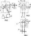
- the transmission-reception head shown in FIG. 1 comprises a laser 1, the beam of which is returned by mirrors 2 and 3 to polarization switching means 4, for example with liquid crystal Control means 5 switch means 4 so that the beam 6 which results therefrom alternately has linear polarizations offset by 90 °.
- the beam 6 is then divided into two parallel beams in a prism 7 and, at the outlet of the prism 7, the two beams thus obtained pass through the polarization splitter 8 which will now be described with reference to FIGS. 2 to 6.
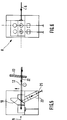
- the separator 8 is formed by a Glan prism 9, the active face 10 of which is crossed by the two beams ( Figures 5 and 6), or reflects them towards a mirror 11 ( Figures 2 and 3), according to their polarization state .
- the face 10 of the Glan prism and the mirror 11 are parallel, so that the exit beams of the separator 8, i.e. either the two crossing beams 12 or the two twice-reflected beams 12 ′, are parallel .
- the large mirror 16 of the telescope 15 comprises only four elementary mirrors, one for each beam coming from the polarization splitter 8. Furthermore, the light beams are folded back inside the telescope by two sets of four plane mirrors 20 and 21, which makes it possible to reduce the length of the device.
- the light backscattered by aerosols from the air, and whose circular polarization is therefore reversed, is recollected by the telescope 15, after which it crosses back the quarter-wave plate 13.
- the backscattered beams 22 and 22 'respectively , penetrating into the polarization splitter 8, are therefore linearly polarized, but with a shift of 90 ° relative to the incident beams.
- the beam 22 coming from the beam 12 having passed through the face 10 of the Glan prism is reflected by this same face (FIG. 5).
- the beam 22 'coming from the beam 12' having been reflected by the face 10 passes through this face (FIG. 2).
- All the backscattered beams are therefore returned to a collimating optic 23 and, from there, to an analyzer 24, via an optical fiber 25.
- the optical fiber 25 is preferably a polarization-conserving fiber, so to allow coherent detection (using a local oscillator) at the level of the analyzer 24.
- the control means 5 switch the polarization switching means 4 alternately from one state to another.
- the polarization splitter 8 alternately allows the beams 12 and 12 ′ to pass, which has the effect of allowing the analyzer 24 to process two measurement axes alternately then the other two axes.
Landscapes
- Physics & Mathematics (AREA)
- Engineering & Computer Science (AREA)
- Electromagnetism (AREA)
- Computer Networks & Wireless Communication (AREA)
- General Physics & Mathematics (AREA)
- Radar, Positioning & Navigation (AREA)
- Remote Sensing (AREA)
- Optical Radar Systems And Details Thereof (AREA)
Applications Claiming Priority (2)
| Application Number | Priority Date | Filing Date | Title |
|---|---|---|---|
| FR9411308 | 1994-09-22 | ||
| FR9411308A FR2725034B1 (fr) | 1994-09-22 | 1994-09-22 | Tete d'emission-reception pour anemometre doppler longitudinal |
Publications (2)
| Publication Number | Publication Date |
|---|---|
| EP0703467A1 true EP0703467A1 (de) | 1996-03-27 |
| EP0703467B1 EP0703467B1 (de) | 2001-06-27 |
Family
ID=9467168
Family Applications (1)
| Application Number | Title | Priority Date | Filing Date |
|---|---|---|---|
| EP95402118A Expired - Lifetime EP0703467B1 (de) | 1994-09-22 | 1995-09-20 | Sender-Emfänger für ein Längsdoppleranemometer |
Country Status (5)
| Country | Link |
|---|---|
| US (1) | US5703679A (de) |
| EP (1) | EP0703467B1 (de) |
| CA (1) | CA2158799A1 (de) |
| DE (1) | DE69521468T2 (de) |
| FR (1) | FR2725034B1 (de) |
Cited By (1)
| Publication number | Priority date | Publication date | Assignee | Title |
|---|---|---|---|---|
| WO2012123668A1 (fr) * | 2011-03-14 | 2012-09-20 | Upwind | Dispositif d'emission et reception, systeme de teledetection et procede d'emission et reception associes |
Families Citing this family (5)
| Publication number | Priority date | Publication date | Assignee | Title |
|---|---|---|---|---|
| EP0829726B1 (de) * | 1996-09-05 | 2003-04-16 | Robert Bosch Gmbh | Verfahren und Vorrichtung zum Erfassen 3-dimensionaler Strömungsstrukturen |
| GB2336050B (en) * | 1998-03-31 | 2003-03-26 | Marconi Gec Ltd | Improvements in or relating to remote air detection |
| FR2947052B1 (fr) * | 2009-06-23 | 2011-07-29 | Thales Sa | Procede de mesure de vitesse d'un aeronef, par anemometrie laser doppler |
| FR2994273B1 (fr) | 2012-07-31 | 2015-04-17 | Thales Sa | Systeme de sonde, sonde mixte de reference primaire pour aeronef, aeronef et procede de mesure associes |
| FR3035209B1 (fr) | 2015-04-20 | 2018-10-05 | Thales | Sonde multifonctions de references primaires pour aeronef, systeme de mesure, aeronef et procede d'obtention de grandeurs physiques associes |
Citations (2)
| Publication number | Priority date | Publication date | Assignee | Title |
|---|---|---|---|---|
| US4199226A (en) * | 1977-04-01 | 1980-04-22 | Institut Fur Angewandte Physik Der Universtitat Bern | Laser transmitting and receiving device |
| DE3435423A1 (de) * | 1984-02-21 | 1985-08-22 | Bundesrepublik Deutschland, vertreten durch den Bundesminister für Wirtschaft, dieser vertreten durch den Präsidenten der Physikalisch-Technischen Bundesanstalt, 3300 Braunschweig | Laser-doppler-anemometer |
Family Cites Families (4)
| Publication number | Priority date | Publication date | Assignee | Title |
|---|---|---|---|---|
| EP0097150B1 (de) * | 1981-12-28 | 1986-11-05 | Dantec Elektronik, Medicinsk Og Videnskabeligt Maleudstyr A/S | Laser-doppler-anemometer |
| US4637717A (en) * | 1984-04-12 | 1987-01-20 | The United States Of America As Represented By The United States Department Of Energy | Dual beam translator for use in Laser Doppler anemometry |
| FR2640755B1 (fr) * | 1988-12-15 | 1991-03-22 | Crouzet Sa | Anemometre laser a plusieurs directions de mesure |
| JP3279116B2 (ja) * | 1994-03-22 | 2002-04-30 | 株式会社豊田中央研究所 | レーザドップラ流速計 |
-
1994
- 1994-09-22 FR FR9411308A patent/FR2725034B1/fr not_active Expired - Fee Related
-
1995
- 1995-09-20 EP EP95402118A patent/EP0703467B1/de not_active Expired - Lifetime
- 1995-09-20 DE DE69521468T patent/DE69521468T2/de not_active Expired - Fee Related
- 1995-09-21 CA CA002158799A patent/CA2158799A1/fr not_active Abandoned
- 1995-09-22 US US08/532,323 patent/US5703679A/en not_active Expired - Fee Related
Patent Citations (2)
| Publication number | Priority date | Publication date | Assignee | Title |
|---|---|---|---|---|
| US4199226A (en) * | 1977-04-01 | 1980-04-22 | Institut Fur Angewandte Physik Der Universtitat Bern | Laser transmitting and receiving device |
| DE3435423A1 (de) * | 1984-02-21 | 1985-08-22 | Bundesrepublik Deutschland, vertreten durch den Bundesminister für Wirtschaft, dieser vertreten durch den Präsidenten der Physikalisch-Technischen Bundesanstalt, 3300 Braunschweig | Laser-doppler-anemometer |
Non-Patent Citations (2)
| Title |
|---|
| BAHNEN R H ET AL: "Laser Doppler velocimeter for multicomponent measurements using an electro-optical modulator demonstrated for a two-component optical configuration", REVIEW OF SCIENTIFIC INSTRUMENTS, JULY 1984, USA, vol. 55, no. 7, ISSN 0034-6748, NEW YORK, NY, US, pages 1090 - 1093 * |
| NASA TECH BRIEFS, vol. 1, no. 2, WASHINGTON DC, US, pages 182 - 183 * |
Cited By (2)
| Publication number | Priority date | Publication date | Assignee | Title |
|---|---|---|---|---|
| WO2012123668A1 (fr) * | 2011-03-14 | 2012-09-20 | Upwind | Dispositif d'emission et reception, systeme de teledetection et procede d'emission et reception associes |
| FR2972879A1 (fr) * | 2011-03-14 | 2012-09-21 | Upwind | Dispositif d'emission et reception, systeme de teledetection et procede d'emission et reception associes. |
Also Published As
| Publication number | Publication date |
|---|---|
| DE69521468T2 (de) | 2001-11-22 |
| US5703679A (en) | 1997-12-30 |
| DE69521468D1 (de) | 2001-08-02 |
| FR2725034B1 (fr) | 1997-01-03 |
| FR2725034A1 (fr) | 1996-03-29 |
| EP0703467B1 (de) | 2001-06-27 |
| CA2158799A1 (fr) | 1996-03-23 |
Similar Documents
| Publication | Publication Date | Title |
|---|---|---|
| EP0635705A2 (de) | Abgewinkeltes Michelson-Interferometer und optischer Wellenlängenmesser auf der Basis eines rotierenden Periscopes | |
| EP0255792B1 (de) | Erkennungssystem zusammen mit einem Retroreflektor und einem Laserstrahl-Modulator | |
| FR2658367A1 (fr) | Laser fournissant deux ondes a des frequences differentes. | |
| EP2376882B1 (de) | Vorrichtung und verfahren zur bestimmung von polarisationsinformationen und polarimetrische bildgebungsvorrichtung | |
| EP0406058A1 (de) | Vorrichtung zur Windgeschwindigkeitsmessung in mittleren Höhen | |
| US4184767A (en) | Frequency agile optical radar | |
| US6204926B1 (en) | Methods and system for optically correlating ultrashort optical waveforms | |
| FR2807522A1 (fr) | Dispositif pour determiner les valeurs d'au moins un parametre de particules, notamment de gouttelettes d'eau | |
| EP0703467B1 (de) | Sender-Emfänger für ein Längsdoppleranemometer | |
| EP0645645B1 (de) | Lasersonde für Geschwindigkeits- und Neigungsmessung | |
| US4850041A (en) | Laser radar with adjustable local oscillator | |
| US4747688A (en) | Fiber optic coherence meter | |
| US5677767A (en) | Fiber ring interferometer using a Kerr medium optical fiber loop | |
| EP0446101A1 (de) | Lasersystem zur Messung des Anstellwinkels eines Flugzeugs | |
| FR2547409A1 (fr) | Compensateur d'oscillations pour gyroscope a laser en anneau | |
| JPH0245138B2 (de) | ||
| WO1994016310A1 (en) | Zeeman ellipsometer | |
| EP0516562B1 (de) | Faseroptische Strommessvorrichtung | |
| US4624573A (en) | Total optical loss measurement device | |
| Wyant | A simple interferometric MTF instrument | |
| EP4078217B1 (de) | Lidar-system mit zwei diffraktiven komponenten | |
| FR2612628A1 (fr) | Dispositif de mesure par interferometrie laser | |
| CH629299A5 (fr) | Dispositif pour determiner la qualite du poli des surfaces optiques. | |
| EP0484310B1 (de) | Vorrichtung zum Messen der Rauhigkeit eines sich bewegenden Metallerzeugnisses | |
| FR2703451A1 (fr) | Dispositif de mesure interférométrique en lumière polarisée. |
Legal Events
| Date | Code | Title | Description |
|---|---|---|---|
| PUAI | Public reference made under article 153(3) epc to a published international application that has entered the european phase |
Free format text: ORIGINAL CODE: 0009012 |
|
| AK | Designated contracting states |
Kind code of ref document: A1 Designated state(s): DE GB |
|
| 17P | Request for examination filed |
Effective date: 19960720 |
|
| 17Q | First examination report despatched |
Effective date: 19990427 |
|
| GRAG | Despatch of communication of intention to grant |
Free format text: ORIGINAL CODE: EPIDOS AGRA |
|
| GRAG | Despatch of communication of intention to grant |
Free format text: ORIGINAL CODE: EPIDOS AGRA |
|
| GRAH | Despatch of communication of intention to grant a patent |
Free format text: ORIGINAL CODE: EPIDOS IGRA |
|
| GRAH | Despatch of communication of intention to grant a patent |
Free format text: ORIGINAL CODE: EPIDOS IGRA |
|
| GRAA | (expected) grant |
Free format text: ORIGINAL CODE: 0009210 |
|
| AK | Designated contracting states |
Kind code of ref document: B1 Designated state(s): DE GB |
|
| REF | Corresponds to: |
Ref document number: 69521468 Country of ref document: DE Date of ref document: 20010802 |
|
| GBT | Gb: translation of ep patent filed (gb section 77(6)(a)/1977) |
Effective date: 20010824 |
|
| REG | Reference to a national code |
Ref country code: GB Ref legal event code: IF02 |
|
| PLBE | No opposition filed within time limit |
Free format text: ORIGINAL CODE: 0009261 |
|
| STAA | Information on the status of an ep patent application or granted ep patent |
Free format text: STATUS: NO OPPOSITION FILED WITHIN TIME LIMIT |
|
| 26N | No opposition filed | ||
| PGFP | Annual fee paid to national office [announced via postgrant information from national office to epo] |
Ref country code: GB Payment date: 20040915 Year of fee payment: 10 |
|
| PGFP | Annual fee paid to national office [announced via postgrant information from national office to epo] |
Ref country code: DE Payment date: 20040916 Year of fee payment: 10 |
|
| PG25 | Lapsed in a contracting state [announced via postgrant information from national office to epo] |
Ref country code: GB Free format text: LAPSE BECAUSE OF NON-PAYMENT OF DUE FEES Effective date: 20050920 |
|
| PG25 | Lapsed in a contracting state [announced via postgrant information from national office to epo] |
Ref country code: DE Free format text: LAPSE BECAUSE OF NON-PAYMENT OF DUE FEES Effective date: 20060401 |
|
| GBPC | Gb: european patent ceased through non-payment of renewal fee |
Effective date: 20050920 |