EP0703542A1 - Verschlüsselungskartenführung für PC-Karte - Google Patents
Verschlüsselungskartenführung für PC-Karte Download PDFInfo
- Publication number
- EP0703542A1 EP0703542A1 EP95305702A EP95305702A EP0703542A1 EP 0703542 A1 EP0703542 A1 EP 0703542A1 EP 95305702 A EP95305702 A EP 95305702A EP 95305702 A EP95305702 A EP 95305702A EP 0703542 A1 EP0703542 A1 EP 0703542A1
- Authority
- EP
- European Patent Office
- Prior art keywords
- card
- integrated circuit
- guide
- connector
- circuit card
- Prior art date
- Legal status (The legal status is an assumption and is not a legal conclusion. Google has not performed a legal analysis and makes no representation as to the accuracy of the status listed.)
- Withdrawn
Links
Images



Classifications
-
- H—ELECTRICITY
- H05—ELECTRIC TECHNIQUES NOT OTHERWISE PROVIDED FOR
- H05K—PRINTED CIRCUITS; CASINGS OR CONSTRUCTIONAL DETAILS OF ELECTRIC APPARATUS; MANUFACTURE OF ASSEMBLAGES OF ELECTRICAL COMPONENTS
- H05K5/00—Casings, cabinets or drawers for electric apparatus
- H05K5/02—Details
- H05K5/0256—Details of interchangeable modules or receptacles therefor, e.g. cartridge mechanisms
- H05K5/026—Details of interchangeable modules or receptacles therefor, e.g. cartridge mechanisms having standardized interfaces
- H05K5/0265—Details of interchangeable modules or receptacles therefor, e.g. cartridge mechanisms having standardized interfaces of PCMCIA type
-
- G—PHYSICS
- G06—COMPUTING OR CALCULATING; COUNTING
- G06K—GRAPHICAL DATA READING; PRESENTATION OF DATA; RECORD CARRIERS; HANDLING RECORD CARRIERS
- G06K7/00—Methods or arrangements for sensing record carriers, e.g. for reading patterns
- G06K7/0013—Methods or arrangements for sensing record carriers, e.g. for reading patterns by galvanic contacts, e.g. card connectors for ISO-7816 compliant smart cards or memory cards, e.g. SD card readers
- G06K7/0047—Methods or arrangements for sensing record carriers, e.g. for reading patterns by galvanic contacts, e.g. card connectors for ISO-7816 compliant smart cards or memory cards, e.g. SD card readers for reading/sensing record carriers having edge contacts
-
- H—ELECTRICITY
- H05—ELECTRIC TECHNIQUES NOT OTHERWISE PROVIDED FOR
- H05K—PRINTED CIRCUITS; CASINGS OR CONSTRUCTIONAL DETAILS OF ELECTRIC APPARATUS; MANUFACTURE OF ASSEMBLAGES OF ELECTRICAL COMPONENTS
- H05K5/00—Casings, cabinets or drawers for electric apparatus
- H05K5/02—Details
- H05K5/0256—Details of interchangeable modules or receptacles therefor, e.g. cartridge mechanisms
- H05K5/0286—Receptacles therefor, e.g. card slots, module sockets, card groundings
Definitions
- This invention relates to devices for guiding a PC card or the like into a card slot, and more particularly to a card guide providing tactile feedback of improper PC card orientation.
- PCMCIA Personal Computer Memory Card International Association
- a PC card is an add-in card that conforms to the PCMCIA specification.
- the PC card is a removable device approximately the same size as a credit card (54 mm x 85.6 mm) designed to plug into a PC connector.
- Release 1 of the PCMCIA specification introduced in September 1990, specified a Type I card that is 3.3 mm thick.
- Type I cards are primarily memory-related peripherals, such as RAM, ROM, EEPROM, and flash memory. Other peripherals such as sound cards are also available as a Type I PC card.
- Type II cards accommodate devices such as a modem, fax, network interface, or sound card.
- Type III cards accommodate devices that require more space, such as a wireless communications device or a rotating storage media (e.g., hard disk).
- a revision of the PCMCIA standard is under consideration for a PC card 32, that may include support for a 32-bit bus interface, multifunction cards, and power management.
- a conventional PC card includes a female connector which couples to a 68-pin male connector inside a PC slot.
- the male and female connectors are the same for Type I, Type II and Type III PC cards. Because, the card heights vary among types, however, Type I, Type II and Type III slots differ. In particular, the slot widths are the same but the slot heights differ.
- a Type I slot can accommodate only a Type I PC card.
- a Type II slot can accommodate only a Type II or a Type I PC card.
- a Type III slot can accommodate a Type III, Type II or a Type I PC card.
- Existing devices for signifying proper orientation of a PC card during insertion are categorized as electronic sensing devices or mechanical insertion prevention devices.
- magnetic sensing devices are useful for cards with a recorded stripe, (e.g., ATM card).
- Electronic and magnetic sensing devices typically determine whether a card is properly oriented only after the card is inserted fully within the slot out of the installer's grasp. Specifically, the sensing devices become active once the card is substantially inserted.
- the circuitry for the sensing devices is relatively expensive and costly to manufacture.
- electronic and magnetic sensing devices require that electrical power be available during the sensing operations. The expense, lack of immediate feedback, and power requirement are undesirable features. Accordingly, there is a need for less expensive, powerless devices providing immediate orientation feedback.
- Mechanical insertion prevention devices typically are less costly than the electronic and mechanical sensor counterparts, and do not require power.
- the known mechanical devices do not provide unequivocal, immediate, tactile or visible feedback of improper orientation.
- ejection mechanisms are necessary, otherwise removal of the improperly oriented card is difficult.
- the difference in position between a properly oriented card and an improperly oriented card is too small to clearly indicate that the card is improperly oriented. Accordingly, there still is a need for an inexpensive mechanical device providing immediate tactile and visible feedback of card orientation.
- card guides prevent an improperly oriented PC card or the like from being inserted a significant distance into a corresponding card slot.
- the installer receives immediate tactile and visible feedback on whether a PC card is improperly oriented.
- the improperly oriented PC card can be inserted only a small distance before it is apparent that the card is not fitting. Tactile feedback occurs soon enough that the installer knows of the problem before removing their grip on the card.
- a pair of card guides are coupled to a PC male connector.
- the connector has a standard width and a standard height defining left and right ends and top and bottom edges.
- the PC card guides are removably coupled to the left and right ends, respectively, of the connector.
- a PC card is received into the guides as the card is inserted and pushed toward the PC male connector. Immediate feedback of an improperly oriented PC card occurs. It is expected that the card is still in the inserter's grasp. Because the card is not inserted all the way, the installer can readily remove the improperly oriented card. Automatic ejection is not needed.
- One advantage of this aspect is that a less expensive PC slot, omitting an ejection mechanism, is achieved.
- each card guide includes a proximal end that engages an end of the PC male connector and a distal flanged end that receives the PC card.
- a guide rail connects the proximal and distal ends of a respective guide mechanism. Because all PC cards have the same height at its card edges, all PC cards fit the guide rails.
- a PC card is fed female connector edge first into a PC slot fitted with the guide mechanisms. The card edges perpendicular to the female connector edge are received at the guide rails. The card first encounters the flanged end of the guide mechanisms which directs the card to the guide rails.
- a properly oriented card is freely pushed along the guide rails to a conventional keying mechanism at the PC connector. As the card is inserted, the rails, then the conventional keying mechanism, align the card. As the card edge approaches the connector pins, the conventional keying mechanism assures proper alignment and mating.
- At least one guide mechanism includes a flexible arm along its guide rail.
- a keying mechanism of this invention responsive to the PC card orientation.
- the card slides over the keying mechanism pushing it aside to traverse the guide rail.
- the PC card is blocked by the keying mechanism so as not to traverse the guide rail.
- the inventive keying mechanism is located away from the male connector and toward the distal end of the guide mechanism.
- an installer feels resistance of an improperly oriented card before the card travels a significant distance within the slot.
- the installer has tactile feedback by feeling the resistance, and visible feedback by seeing that the card is not installed nearly as far as it should when a proper connection occurs. With a significant length of the card protruding from the slot, the card is easily grasped and removed.
- One advantage of the invention is that feedback occurs soon enough during the installation motion to block the normal progress and allow easy removal without the need of an ejection mechanism. Another advantage is that the mechanical blocking provides feedback at a significantly lesser cost than electronic and magnetic sensing devices used for similar objectives. Another advantage is that the computing or peripheral device hosting the PC card need not be powered on for proper feedback to occur.
- the card guides are mechanical mechanisms which do not require electronic power inputs.
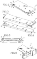
- Fig. 1 shows a perspective view of a PC card 10, PC male connector 12 and card guide mechanisms 14, 16 according to an embodiment of this invention.
- the PC card 10 embodies an electronic circuit coupled to a host computer or other electronic device through the PC male connector 12.
- the card guides 14, 16 removably engage the connector 12 at opposing connector ends 18, 20.
- the card guides 14, 16 receive the PC card 10 as the card 10 is inserted into a slot containing the card guides 14, 16 and connector 12.
- the card guides 14, 16 serve as rails along which the card 10 is moved.
- At least one card guide 14 includes a keying mechanism 82 (see Fig. 7) to allow passage of a properly oriented PC card 10, and to resist passage of an improperly oriented PC card 10.
- Figs. 1-4 show a Type I PC card.
- a Type I card has a width of 54 mm, a length of 85.6 mm and a height of 3.3 mm.
- a first edge 22 corresponding to the card width defines a female connector having 68 openings for mating with 68 pins 24 of the male connector 12.
- Second and third edges 26, 28 corresponding to the card length run perpendicular to the first edge 22.
- a fourth edge 30 corresponding to the card width is opposite the first edge 22.
- the first and fourth edges are 54 mm by 3.3 mm.
- the second and third edges are 85.6 mm by 3.3 mm.
- a Type II or Type III PC card has the same 54 mm width and 85.6 mm length, but a greater height - (i.e., Type II is 5.0 mm; Type III is 10.5 mm).
- the four edges regardless of whether a Type I, Type II or Type III card have the same 3.3 mm height.
- the first and fourth edges 22 and 30 have the same dimensions regardless of which type of PC card.
- the second and third edges 26, 28 have the same dimensions regardless of which type of PC card.
- a first elongated groove 32 is defined at the second edge 26 of card 10 to extend from the first edge 22 toward the fourth edge 30 for approximately 11 mm.
- a second elongated groove 34 is defined at the third edge 28 to extend from the first edge 22 toward the fourth edge 30 for approximately 11 mm.
- Each groove 32, 34 is approximately 1.5 mm deep.
- the first groove 32 is open on two sides, one at edge 22 and one at edge 26.
- the second groove 34 is open on three sides, one at edge 22, one at edge 28 and one at card face 44.
- the first groove 32 is defined by three walls 36, 38, 40 extending from edge 22 along edge 26 to end at a fourth wall 42.
- the second groove 34 is defined by two walls 46, 48 extending from edge 22 along edge 28 to end at a third wall 50.
- the card 10 When inserting a PC card 10 into a PC card slot, the card 10 can be oriented in any of four ways. According to a first orientation and a second orientation, the edge 22 which defines a female connector is inserted first. According to a third orientation and a fourth orientation, the edge 30 is inserted first. A user can readily see that the female connector at edge 22 should be inserted first, so incorrectly inserting a card according to the third or fourth orientations is less common. Determining whether the first or second orientation is correct requires closer inspection by the user According to the first orientation (see Fig. 1), face 44 is up so that the first groove 32 is inserted at connector end 18, and the second groove 34 is inserted at connector end 20.
- face 44 is down so that the first groove 32 is inserted at connector end 20, and the second groove 34 is inserted at connector end 18.
- the first orientation is correct, while the second, third and fourth orientations are incorrect.
- Figs. 1, 5 and 6 show a PC male connector 12.
- the connector 12 includes 68 pins for mating with the 68 openings at the PC card edge 22.
- the male connector 12 receives the card 10 at connector rails 62, 64.
- One connector rail 62 extends outward at connector end 18, while the other connector rail 64 extends outward at connector end 20.
- Each connector rail 62, 64 defines a conventional keying mechanism to prevent the card 10 from making an electrical connection when improperly oriented.
- One connector rail 62 defines a first ridge 66 (see Fig. 5) which aligns with the first groove 32 (see Figs. 1 and 3) of the card 10.
- the other connector rail 64 defines a second ridge 68 (see Fig.
- card guide mechanisms 14, 16 are coupled to the connector 12 to define an additional keying mechanism which exaggerates the positional difference between a properly oriented and an improperly oriented PC card.
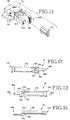
- Fig. 1 and Figs. 7-11 show a first guide mechanism 14, while Fig. 1 and Figs. 12-14 show a second guide mechanism 16.
- the first guide 14 includes a flanged distal end 74, a guide rail 76, a movable first cantilever arm 80, a keying guide mechanism 82, a support 84, a locking second arm 86, and a proximal end 88.
- the PC card 10 is received at the distal end 74. Flanging of the distal end 74 increases the opening for receiving the card 10 and biases the card 10 toward the guide rail 76. During insertion, the card 10 is pushed along the guide rail 76 toward the guide mechanism's proximal end 88.
- the first arm 80 forms a wall of the rail 76 and extends from a fixed end near the first guide's proximal end 88 to a free end near the first guide's distal end 74.
- the keying guide 82 is formed at the first arm's free end to resist passage of an improperly oriented card 10.
- the keying guide 82 defines a blocking surface 96 and an inclined surface 98.
- the first guide 14 is removably attached to the connector 12 at the guide's proximal end 88.
- the attachment is characterized by a locking arm 86, an engaging rail 70 and a flush support 84.
- the locking arm 86 and support 84 are part of the first guide mechanism 14.
- the engaging rail 70 is part of the PC connector 12.
- the male connector 12 includes an engaging rail structure 70 at connector end 18 and connector end 20 (not shown). Each engaging rail 70 runs along the outer edge of the respective connector rails 62, 64.
- the locking arm 86 (see Fig. 7) is pushed over the engaging rail 70 (see Fig. 6) as the rail 70 is received into a slot 90 at the base of the locking arm 86.
- the locking arm 86 extends beyond the engaging rail 70 to hook to a far side of the engaging rail 70.
- the engaging rail 70 is attached to the connector rail 62 along its entire length to maintain a constant position after repeated guide 14 installations.
- a cross-section of the engaging rail 70 in one embodiment is T-shaped.
- the first guide 14 defines a T-shaped slot for receiving the engaging rail 70.
- the guide rail 76 When an attachment is formed, the guide rail 76 abuts the connector rail 62.
- a support 84 extends beyond the guide rail 76 along two walls 92, 94 common to the guide rail 76 to surround two exterior walls of the connector rail 62.
- the slot 90 is formed in one wall 94 and receives the engaging rail 70.
- the second guide 16 includes a flanged distal end 174, a guide rail 176, a support 184, and a locking second arm 186, and a proximal end 188.
- the PC card 10 is received at the distal end 174. Flanging of the distal end 174 increases the opening for receiving the card 10 and biases the card 10 toward the guide rail 176. During insertion, the card 10 is pushed along the guide rail 176 toward the second guide mechanism's proximal end 188.
- the second guide 16 is removably attached to the connector 12 at the guide's proximal end 188.
- the attachment is characterized by a locking arm 186, an engaging rail 70 and a flush support 184.
- the locking arm 186 and support 184 are part of the second guide mechanism 16.
- the engaging rail 70 is part of the PC connector 12.
- the locking arm 186 (see Fig. 13) is pushed over the engaging rail 70 (like in Fig. 6) as the engaging rail 70 is received into a slot 190 at the base of the locking arm 186.
- the locking arm 186 extends beyond the engaging rail 70 to hook to a far side of the engaging rail 70.
- the engaging rail 70 is attached to the connector rail 62 along its entire length to maintain a constant position after repeated guide 16 installations.
- a cross-section of the engaging rail 70 in one embodiment is T-shaped. (See Fig. 11).
- the second guide 16 defines a T-shaped slot 190 for receiving the engaging rail 70. (See Fig. 11)
- the guide rail 176 When an attachment is formed, the guide rail 176 abuts the connector rail 64.
- a support 184 extends beyond the guide rail 176 along two walls 192, 193 of the three walls 192-194 common to the guide rail 176 to surround two exterior walls of the connector rail 64.
- the slot 190 is formed in one wall 193 and receives the engaging rail 70.
- a PC card 10 having a first orientation is inserted into a PC slot including PC connector 12 and first and second card guides 14, 16.
- the keying mechanism 82 is encountered at arm 80 of the first guide 14.
- the card's first groove 32 aligns with the keying mechanism 82.
- the first groove 32 includes a wall 36. A portion 202 of the wall 36 encounters the inclined surface 98 of the keying mechanism 82. As the card 10 is pushed further, the portion 202 of the card pushes at the inclined surface 98 to cantilever the arm 80 out of the path of the card 10. The card 10, therefore can be fully inserted to the connector 12 for operation.
- the arm 80 returned to its unbiased position in which the keying mechanism 82 is in the card path.
- a PC card 10 having a second orientation is inserted into a PC slot, including a PC connector 12 and first and second card guides 14, 16.
- the keying mechanism 82 is encountered at arm 80 of the first guide 14.
- the second card groove 34 aligns with the keying mechanism 82.
- the second groove 32 includes a wall 46. A portion 204 of the wall 46 passes freely past the keying mechanism 82 along guide rail 76. As the card 10 progresses, however, the end wall 50 of the second groove 34 encounters the blocking surface 96 of the keying mechanism (see Fig. 17).
- the blocking wall 96 and groove end wall 50 are parallel and abut face to face. There is no wall at groove 34 to encounter the inclined surface 98 of the keying mechanism 82. Thus, the keying mechanism 82 resists further advancement of the card 10. Such resistance is tactile feedback to the inserter that the card is improperly oriented. The inserter also can see that the card 10 is protruding substantially more than if a proper connection is made. The noticeable difference in position is visual feedback that the card 10 is improperly oriented. Because the keying mechanism 82 is located toward the distal end 74 of the card guide 14, the resistance occurs relatively early in the insertion process. This provides the inserter with immediate feedback to remove the card before pushing further.
- the arm 80 carrying the keying mechanism 82 may vary in length and position.
- the keying mechanism 82 preferably is away from the proximal end 88 of the guide 14 to block an improperly oriented card a noticeable distance preceding the male connector 12.
- the arm 80 is biased into the card path along the guide rail 76.
- the material forming the arm defines the bias.
- a spring or other bias creating structure is included to bias the arm 80 into the card path.
- the guide rails 76, 176 are formed by three walls surrounding an edge of a received PC card. In other embodiments, the guide rails 76, 176 are formed by one or two flat or curved walls.
- the locking arm 86, slot 90 and engaging rail 70 define one manner of removably attaching the first guide mechanism 14 to the male connector 12.
- the locking arm 186, slot 190 and engaging rail 70 define one manner of attaching the second guide mechanism 16 to the male connector 12.
- Alternative structures for permanently or removably coupling the guide mechanisms 14, 16 to the male connector 12 also may be implemented.
- the guide rails can be molded with the male connector so as to avoid the need of engaging parts.
- fastening devices would appreciate the numerous ways to removably attach a guide mechanism 14, 16 to a male connector 12.
- One meritorious and advantageous effect of the invention is that feedback occurs soon enough during the installation motion to block the normal progress and allow easy removal of the PC card without the need of an ejection mechanism.
- Another advantage is that the mechanical blocking performed by the keying mechanism 82 provides feedback at a significantly lesser cost than electronic and magnetic sensing devices used for similar objectives.
- Another advantage is that a computing or peripheral device hosting the PC slot need not be powered on for proper feedback to occur.
- the card guides 14, 16 are mechanical mechanisms which do not require electronic power inputs.
- card guide is described for use with a Type I, II, or III PC card and PC connector, future PC card/connector types (e.g., PC card 32) and current or future PC-like cards having keying grooves and corresponding connectors also are contemplated.
- Integrated circuit cards including (i) Type I, Type II or Type III PC cards; (ii) cards complying with revised or future PC card-type specifications; (iii) portable encased electronic circuit cards having a connector for engaging a host device in which a groove is formed near at least one end of the card's connector to aid in alignment and to prevent engaging a mis-oriented card to a host connector; and (iv) equivalents are encompassed.
- integrated circuit connectors are contemplated for receiving the PC and PC-like cards and defining a structure related to the card's groove to aid in alignment and prevent engagement by a mis-oriented card.
- the precise physical dimensions and the number of pins/openings for a card or connector vary according to alternative embodiments. Therefore, the foregoing description should not be taken as limiting the scope of the inventions which are defined by the appended claims.
Landscapes
- Engineering & Computer Science (AREA)
- Microelectronics & Electronic Packaging (AREA)
- Artificial Intelligence (AREA)
- Computer Vision & Pattern Recognition (AREA)
- Physics & Mathematics (AREA)
- General Physics & Mathematics (AREA)
- Theoretical Computer Science (AREA)
- Details Of Connecting Devices For Male And Female Coupling (AREA)
- Conveying Record Carriers (AREA)
- Coupling Device And Connection With Printed Circuit (AREA)
Applications Claiming Priority (2)
| Application Number | Priority Date | Filing Date | Title |
|---|---|---|---|
| US311083 | 1981-10-13 | ||
| US08/311,083 US5483422A (en) | 1994-09-23 | 1994-09-23 | Keying card guide for PC card |
Publications (1)
| Publication Number | Publication Date |
|---|---|
| EP0703542A1 true EP0703542A1 (de) | 1996-03-27 |
Family
ID=23205323
Family Applications (1)
| Application Number | Title | Priority Date | Filing Date |
|---|---|---|---|
| EP95305702A Withdrawn EP0703542A1 (de) | 1994-09-23 | 1995-08-16 | Verschlüsselungskartenführung für PC-Karte |
Country Status (3)
| Country | Link |
|---|---|
| US (1) | US5483422A (de) |
| EP (1) | EP0703542A1 (de) |
| JP (1) | JPH08106954A (de) |
Families Citing this family (23)
| Publication number | Priority date | Publication date | Assignee | Title |
|---|---|---|---|---|
| JPH04329415A (ja) * | 1991-04-30 | 1992-11-18 | Fujitsu Ltd | カード型入出力インタフェース装置及びシステム |
| US5867366A (en) * | 1992-12-17 | 1999-02-02 | Siemens Aktiengesellschaft | Electronic module and plastic substrate to accept and hold the electronic module |
| GB2287106A (en) * | 1994-02-16 | 1995-09-06 | Ibm | Connection of adaptors for multiple bus architectures |
| US6347891B1 (en) | 1995-04-26 | 2002-02-19 | Ohio Electronic Engravers, Inc. | Engraving system and method comprising different engraving devices |
| US5841993A (en) * | 1996-01-02 | 1998-11-24 | Ho; Lawrence | Surround sound system for personal computer for interfacing surround sound with personal computer |
| JP3173438B2 (ja) * | 1997-06-04 | 2001-06-04 | ソニー株式会社 | メモリカード及び装着装置 |
| US5860828A (en) * | 1997-06-12 | 1999-01-19 | United States Of America | PCMCIA card connector that minimizes bent contact pins |
| US5903432A (en) * | 1997-09-19 | 1999-05-11 | Intel Corportation | Computer package with a polygonal shaped motherboard |
| US6449163B1 (en) * | 1998-06-08 | 2002-09-10 | Intel Corporation | Inboard retention system for processor enclosure assemblies with substrate alignment |
| US6356456B2 (en) * | 1998-06-23 | 2002-03-12 | Intel Corporation | Low pin count card retainer |
| TW398640U (en) * | 1998-10-23 | 2000-07-11 | Hon Hai Prec Ind Co Ltd | Holding device for chip module |
| US6307754B1 (en) | 1999-12-09 | 2001-10-23 | Gateway, Inc. | Circuit card guide |
| JP4256052B2 (ja) * | 2000-04-20 | 2009-04-22 | 北川工業株式会社 | 基板保持具 |
| TW453537U (en) * | 2000-09-29 | 2001-09-01 | Hon Hai Prec Ind Co Ltd | Connector device |
| TW471735U (en) * | 2000-11-23 | 2002-01-01 | Hon Hai Prec Ind Co Ltd | Connector of card reader |
| TW200516395A (en) * | 2003-11-12 | 2005-05-16 | Power Data Comm Co Ltd | The memory card control chip with multiple control |
| US7284702B2 (en) * | 2004-03-12 | 2007-10-23 | Scm Microsystems (U.S.) Inc. | Adapter for digital media reader |
| TWM276353U (en) * | 2005-02-03 | 2005-09-21 | Egbn Electronics Ltd | Card edge connector |
| CN101521322B (zh) * | 2008-11-07 | 2011-06-01 | 昆山上正电子科技有限公司 | 记忆卡连接器的制造方法 |
| CN102685276B (zh) * | 2011-03-11 | 2015-03-18 | 索尼爱立信移动通讯有限公司 | 具有防呆功能的sim卡槽和包括该sim卡槽的电子设备 |
| JP6545046B2 (ja) * | 2015-08-28 | 2019-07-17 | 任天堂株式会社 | 雌コネクタ及び雌コネクタと雄コネクタとの接続構造 |
| US10691183B2 (en) * | 2018-01-17 | 2020-06-23 | Facebook, Inc. | Apparatus, system, and method for minimizing installation footprints of expansion cards |
| JP7462603B2 (ja) * | 2020-04-01 | 2024-04-05 | 株式会社バンダイ | 演出出力システム |
Citations (1)
| Publication number | Priority date | Publication date | Assignee | Title |
|---|---|---|---|---|
| EP0195865A2 (de) * | 1985-03-25 | 1986-10-01 | Mips Co., Ltd. | Verbindung mit Einführungsvorrichtung für eine Karte mit integrierter Schaltung sowie eine solche Karte |
Family Cites Families (2)
| Publication number | Priority date | Publication date | Assignee | Title |
|---|---|---|---|---|
| US4887188A (en) * | 1987-12-22 | 1989-12-12 | Casio Computer Co., Ltd. | Connector for a memory card |
| US5155663A (en) * | 1990-02-19 | 1992-10-13 | Fuji Photo Film Co., Ltd. | Memory cartridge system with adapter |
-
1994
- 1994-09-23 US US08/311,083 patent/US5483422A/en not_active Expired - Fee Related
-
1995
- 1995-08-16 EP EP95305702A patent/EP0703542A1/de not_active Withdrawn
- 1995-09-08 JP JP7256758A patent/JPH08106954A/ja active Pending
Patent Citations (1)
| Publication number | Priority date | Publication date | Assignee | Title |
|---|---|---|---|---|
| EP0195865A2 (de) * | 1985-03-25 | 1986-10-01 | Mips Co., Ltd. | Verbindung mit Einführungsvorrichtung für eine Karte mit integrierter Schaltung sowie eine solche Karte |
Non-Patent Citations (1)
| Title |
|---|
| STRASS: "PCMCIA: Karten gut gemischt", ELEKTRONIK, vol. 43, no. 25, MUNCHEN DE, pages 79 - 86 * |
Also Published As
| Publication number | Publication date |
|---|---|
| US5483422A (en) | 1996-01-09 |
| JPH08106954A (ja) | 1996-04-23 |
Similar Documents
| Publication | Publication Date | Title |
|---|---|---|
| US5483422A (en) | Keying card guide for PC card | |
| US6643125B2 (en) | Card-shaped storage medium and information processing apparatus having guide portion for the same | |
| US6129572A (en) | Electrical connector with latch to retain IC card | |
| CA2071381C (en) | Electronic apparatus, card-type electronic component used with the electronic apparatus, and electronic system with expanding apparatus for expanding function of electronic apparatus | |
| EP0195865A2 (de) | Verbindung mit Einführungsvorrichtung für eine Karte mit integrierter Schaltung sowie eine solche Karte | |
| EP0432803A2 (de) | Funktionserweiterungsgerät und Verbindungseinheit für kompakte elektronische Einrichtung | |
| EP1465102A1 (de) | Kartenartiges Terminal | |
| US6421246B1 (en) | PC card that receives chip card | |
| EP2154636A1 (de) | Speicherkarte | |
| US6913492B2 (en) | Connector device for card into which plural kinds of cards of different shapes can be inserted | |
| US6269005B1 (en) | PCMCIA connector | |
| US20120156918A1 (en) | Connector assembly | |
| CN102522650A (zh) | 电子设备以及连接器 | |
| US6139338A (en) | CF card adapter | |
| EP0663649B1 (de) | PCMCIA Steckverbindungsanordnung | |
| US5402310A (en) | Docking apparatus for a portable data processing unit having undercuts as guide members | |
| US20080144259A1 (en) | Mounting apparatus for electronic device | |
| US6663403B2 (en) | Electrical card connector having polarization mechanism | |
| GB2260634A (en) | Connector apparatus | |
| EP2705580B1 (de) | Elektrischer steckverbinder mit einem schlüssel zur vermeidung von kontaktschäden | |
| US5655935A (en) | Receptacle contact used in an electrical connector | |
| CA1270341A (en) | Pluggable electronic cartridge extractor | |
| US6000965A (en) | Retaining apparatus for a connector | |
| CN214542742U (zh) | 接口卡的限位结构 | |
| CN223956068U (zh) | 写读码设备 |
Legal Events
| Date | Code | Title | Description |
|---|---|---|---|
| PUAI | Public reference made under article 153(3) epc to a published international application that has entered the european phase |
Free format text: ORIGINAL CODE: 0009012 |
|
| AK | Designated contracting states |
Kind code of ref document: A1 Designated state(s): DE FR GB IT |
|
| 17P | Request for examination filed |
Effective date: 19960902 |
|
| 17Q | First examination report despatched |
Effective date: 19990510 |
|
| STAA | Information on the status of an ep patent application or granted ep patent |
Free format text: STATUS: THE APPLICATION IS DEEMED TO BE WITHDRAWN |
|
| 18D | Application deemed to be withdrawn |
Effective date: 19990921 |