EP0703676B1 - Dispositif de communication portatif et carte à puce associée - Google Patents
Dispositif de communication portatif et carte à puce associée Download PDFInfo
- Publication number
- EP0703676B1 EP0703676B1 EP95114672A EP95114672A EP0703676B1 EP 0703676 B1 EP0703676 B1 EP 0703676B1 EP 95114672 A EP95114672 A EP 95114672A EP 95114672 A EP95114672 A EP 95114672A EP 0703676 B1 EP0703676 B1 EP 0703676B1
- Authority
- EP
- European Patent Office
- Prior art keywords
- card
- signal
- data
- main body
- body case
- Prior art date
- Legal status (The legal status is an assumption and is not a legal conclusion. Google has not performed a legal analysis and makes no representation as to the accuracy of the status listed.)
- Expired - Lifetime
Links
Images


Classifications
-
- H—ELECTRICITY
- H04—ELECTRIC COMMUNICATION TECHNIQUE
- H04Q—SELECTING
- H04Q9/00—Arrangements in telecontrol or telemetry systems for selectively calling a substation from a main station, in which substation desired apparatus is selected for applying a control signal thereto or for obtaining measured values therefrom
-
- G—PHYSICS
- G06—COMPUTING OR CALCULATING; COUNTING
- G06K—GRAPHICAL DATA READING; PRESENTATION OF DATA; RECORD CARRIERS; HANDLING RECORD CARRIERS
- G06K19/00—Record carriers for use with machines and with at least a part designed to carry digital markings
- G06K19/005—Record carriers for use with machines and with at least a part designed to carry digital markings the record carrier comprising an arrangement to facilitate insertion into a holding device, e.g. an arrangement that makes the record carrier fit into an etui or a casing
-
- B—PERFORMING OPERATIONS; TRANSPORTING
- B60—VEHICLES IN GENERAL
- B60R—VEHICLES, VEHICLE FITTINGS, OR VEHICLE PARTS, NOT OTHERWISE PROVIDED FOR
- B60R25/00—Fittings or systems for preventing or indicating unauthorised use or theft of vehicles
- B60R25/10—Fittings or systems for preventing or indicating unauthorised use or theft of vehicles actuating a signalling device
-
- G—PHYSICS
- G06—COMPUTING OR CALCULATING; COUNTING
- G06K—GRAPHICAL DATA READING; PRESENTATION OF DATA; RECORD CARRIERS; HANDLING RECORD CARRIERS
- G06K19/00—Record carriers for use with machines and with at least a part designed to carry digital markings
- G06K19/04—Record carriers for use with machines and with at least a part designed to carry digital markings characterised by the shape
- G06K19/041—Constructional details
- G06K19/042—Constructional details the record carrier having a form factor of a credit card and including a small sized disc, e.g. a CD or DVD
- G06K19/045—Constructional details the record carrier having a form factor of a credit card and including a small sized disc, e.g. a CD or DVD the record carrier being of the non-contact type, e.g. RFID, and being specially adapted for attachment to a disc, e.g. a CD or DVD
-
- G—PHYSICS
- G06—COMPUTING OR CALCULATING; COUNTING
- G06K—GRAPHICAL DATA READING; PRESENTATION OF DATA; RECORD CARRIERS; HANDLING RECORD CARRIERS
- G06K7/00—Methods or arrangements for sensing record carriers, e.g. for reading patterns
- G06K7/10—Methods or arrangements for sensing record carriers, e.g. for reading patterns by electromagnetic radiation, e.g. optical sensing; by corpuscular radiation
- G06K7/10544—Methods or arrangements for sensing record carriers, e.g. for reading patterns by electromagnetic radiation, e.g. optical sensing; by corpuscular radiation by scanning of the records by radiation in the optical part of the electromagnetic spectrum
- G06K7/10821—Methods or arrangements for sensing record carriers, e.g. for reading patterns by electromagnetic radiation, e.g. optical sensing; by corpuscular radiation by scanning of the records by radiation in the optical part of the electromagnetic spectrum further details of bar or optical code scanning devices
- G06K7/1097—Optical sensing of electronic memory record carriers, such as interrogation of RFIDs with an additional optical interface
-
- G—PHYSICS
- G06—COMPUTING OR CALCULATING; COUNTING
- G06Q—INFORMATION AND COMMUNICATION TECHNOLOGY [ICT] SPECIALLY ADAPTED FOR ADMINISTRATIVE, COMMERCIAL, FINANCIAL, MANAGERIAL OR SUPERVISORY PURPOSES; SYSTEMS OR METHODS SPECIALLY ADAPTED FOR ADMINISTRATIVE, COMMERCIAL, FINANCIAL, MANAGERIAL OR SUPERVISORY PURPOSES, NOT OTHERWISE PROVIDED FOR
- G06Q20/00—Payment architectures, schemes or protocols
- G06Q20/30—Payment architectures, schemes or protocols characterised by the use of specific devices or networks
- G06Q20/34—Payment architectures, schemes or protocols characterised by the use of specific devices or networks using cards, e.g. integrated circuit [IC] cards or magnetic cards
- G06Q20/341—Active cards, i.e. cards including their own processing means, e.g. including an IC or chip
-
- G—PHYSICS
- G07—CHECKING-DEVICES
- G07B—TICKET-ISSUING APPARATUS; FARE-REGISTERING APPARATUS; FRANKING APPARATUS
- G07B15/00—Arrangements or apparatus for collecting fares, tolls or entrance fees at one or more control points
- G07B15/06—Arrangements for road pricing or congestion charging of vehicles or vehicle users, e.g. automatic toll systems
- G07B15/063—Arrangements for road pricing or congestion charging of vehicles or vehicle users, e.g. automatic toll systems using wireless information transmission between the vehicle and a fixed station
-
- G—PHYSICS
- G07—CHECKING-DEVICES
- G07C—TIME OR ATTENDANCE REGISTERS; REGISTERING OR INDICATING THE WORKING OF MACHINES; GENERATING RANDOM NUMBERS; VOTING OR LOTTERY APPARATUS; ARRANGEMENTS, SYSTEMS OR APPARATUS FOR CHECKING NOT PROVIDED FOR ELSEWHERE
- G07C9/00—Individual registration on entry or exit
- G07C9/20—Individual registration on entry or exit involving the use of a pass
- G07C9/28—Individual registration on entry or exit involving the use of a pass the pass enabling tracking or indicating presence
-
- G—PHYSICS
- G07—CHECKING-DEVICES
- G07C—TIME OR ATTENDANCE REGISTERS; REGISTERING OR INDICATING THE WORKING OF MACHINES; GENERATING RANDOM NUMBERS; VOTING OR LOTTERY APPARATUS; ARRANGEMENTS, SYSTEMS OR APPARATUS FOR CHECKING NOT PROVIDED FOR ELSEWHERE
- G07C9/00—Individual registration on entry or exit
- G07C9/20—Individual registration on entry or exit involving the use of a pass
- G07C9/29—Individual registration on entry or exit involving the use of a pass the pass containing active electronic elements, e.g. smartcards
-
- G—PHYSICS
- G07—CHECKING-DEVICES
- G07F—COIN-FREED OR LIKE APPARATUS
- G07F7/00—Mechanisms actuated by objects other than coins to free or to actuate vending, hiring, coin or paper currency dispensing or refunding apparatus
- G07F7/08—Mechanisms actuated by objects other than coins to free or to actuate vending, hiring, coin or paper currency dispensing or refunding apparatus by coded identity card or credit card or other personal identification means
- G07F7/0873—Details of the card reader
- G07F7/088—Details of the card reader the card reader being part of the point of sale [POS] terminal or electronic cash register [ECR] itself
- G07F7/0886—Details of the card reader the card reader being part of the point of sale [POS] terminal or electronic cash register [ECR] itself the card reader being portable for interacting with a POS or ECR in realizing a payment transaction
-
- G—PHYSICS
- G07—CHECKING-DEVICES
- G07F—COIN-FREED OR LIKE APPARATUS
- G07F7/00—Mechanisms actuated by objects other than coins to free or to actuate vending, hiring, coin or paper currency dispensing or refunding apparatus
- G07F7/08—Mechanisms actuated by objects other than coins to free or to actuate vending, hiring, coin or paper currency dispensing or refunding apparatus by coded identity card or credit card or other personal identification means
- G07F7/10—Mechanisms actuated by objects other than coins to free or to actuate vending, hiring, coin or paper currency dispensing or refunding apparatus by coded identity card or credit card or other personal identification means together with a coded signal, e.g. in the form of personal identification information, like personal identification number [PIN] or biometric data
- G07F7/1008—Active credit-cards provided with means to personalise their use, e.g. with PIN-introduction/comparison system
-
- H—ELECTRICITY
- H04—ELECTRIC COMMUNICATION TECHNIQUE
- H04B—TRANSMISSION
- H04B1/00—Details of transmission systems, not covered by a single one of groups H04B3/00 - H04B13/00; Details of transmission systems not characterised by the medium used for transmission
- H04B1/38—Transceivers, i.e. devices in which transmitter and receiver form a structural unit and in which at least one part is used for functions of transmitting and receiving
- H04B1/3816—Mechanical arrangements for accommodating identification devices, e.g. cards or chips; with connectors for programming identification devices
-
- H—ELECTRICITY
- H04—ELECTRIC COMMUNICATION TECHNIQUE
- H04L—TRANSMISSION OF DIGITAL INFORMATION, e.g. TELEGRAPHIC COMMUNICATION
- H04L63/00—Network architectures or network communication protocols for network security
- H04L63/04—Network architectures or network communication protocols for network security for providing a confidential data exchange among entities communicating through data packet networks
-
- H—ELECTRICITY
- H04—ELECTRIC COMMUNICATION TECHNIQUE
- H04W—WIRELESS COMMUNICATION NETWORKS
- H04W92/00—Interfaces specially adapted for wireless communication networks
- H04W92/04—Interfaces between hierarchically different network devices
- H04W92/08—Interfaces between hierarchically different network devices between user and terminal device
-
- H—ELECTRICITY
- H04—ELECTRIC COMMUNICATION TECHNIQUE
- H04B—TRANSMISSION
- H04B1/00—Details of transmission systems, not covered by a single one of groups H04B3/00 - H04B13/00; Details of transmission systems not characterised by the medium used for transmission
- H04B1/38—Transceivers, i.e. devices in which transmitter and receiver form a structural unit and in which at least one part is used for functions of transmitting and receiving
- H04B2001/3894—Waterproofing of transmission device
Definitions
- the present invention relates to a signal transmission system.
- EP -A- 0 159 539 suggests in connection with Figure 1 an input/output device (2) capable of receiving therein a chip card (1).
- the input/output device comprises operation means (Bedienungsimplantation), transmission and receiving means (Sende-/Empfangs-Dioden) as well as a battery (see page 4, line 28).
- Input/output device (2) is preferably made of plastic and, as shown in Figure 1, has an envelope-like form.
- the proposed system further comprises a fixed site transmission and receiving means (3) for communication with the input/output unit (2).
- processor (12) of IC card (1) may perform a data encryption function.
- US -A- 4,277,837 suggests a personal portable terminal for financial transactions adapted for use with one or more data storage and transfer cards and other external devices, such as point of sale terminals.
- the transaction device includes keyboard means for entering transaction data and control information, means for temporarily storing transaction data and logic means for performing arithmetic, logical and control operations.
- Said logic means further includes means for storing predetermined programs, which are activated by instructions entered via the keyboard.
- display means for selectively displaying transaction data and means for transferring selected data from the transaction device into suitable storage means located in the other external device and into at least one data storage and transfer card.
- the IC card employs a transmitter that uses ID data stored in the IC card to transmit the driver's particular aerial propagation signal.
- the IC card can thereby be used as a portable communication device, for example, in a keyless entry system.
- the portable communication device of this type can be very valuable and simple to use and has great promise.
- a driver's license can be made in the form of an IC card.
- an IC card driver's license it is necessary to provide an IC card reader on the car.
- the system configuration is complicated, and the IC card reader can become damaged by water, dust and the like, thereby reducing its reliability. For these reasons, problems can arise when the IC card driver's license is applied to other uses.
- the object of the present invention to provide a signal transmission system which may be used for easy and secure transmission of data stored on IC cards.
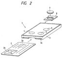
- Fig. 2 shows a portable communication device 1 and an IC card 2.
- the IC card 2 is, for example, an ID card or a driver's license.
- An IC chip 2a is embedded in the IC card 2, and includes a CPU, an EEPROM and the like.
- the surface of the IC card 2 has a photograph 2b of the IC card owner and necessary characters (not shown) by printing or by embossing.
- the IC card 2 contains signal transmitting and receiving means (which is designated by 11 in Fig. 1) that are used not only to transmit and receive a signal to and from external equipment but also to receive electric power.
- the signal transmitting and receiving means can be an ordinary contact device or a non-contact device using inductive coupling, photo coupling, capacitive coupling, or the like.
- the portable communication device 1 includes a main body case 3 structured as a holder that is mounted with the IC card 2 stored therein.
- the main body case 3 is a thin rectangular container that includes on an end face thereof a slit 3a for insertion of the IC card 2.
- a button type battery 7 is mounted into the main body case 3 through a cartridge 8.
- Fig. 1 shows a functional block diagram of the electric structures of the portable communication device 1 and IC card 2 as well as the electric structure of a signal transmission system using the portable communication device 1 and IC card 2.
- the IC card 2 when it is expressed by means of functional blocks, includes a control part 9, a memory part 10 comprising the EEPROM provided in the IC card 2a, and the above-mentioned signal transmission means 11.
- the memory part 10 is structured such that the ID data particular to the owner of the IC card 2 are stored in the given memory areas of the memory part 10 in an unrewritable manner, so that arbitrary data can be written into the other memory areas.
- the main body case 3 of the portable communication device 1 also includes a control device or transmission control means 12, a communication means 13, a cipher device 14, an amplifying device 15, and an aerial propagation signal generation device 16.
- the control device 12 includes a microcomputer and controls the output of battery 7 to the communication device 13, cipher device 14, amplifying device 15 and aerial transmission signal propagation device 16. Control device 12 also directs operations to be described later according to the operations of the respective switches 4, 5, and 6.
- the communication device 13 in the IC card 2 mounted state supplies power to the IC card 2 and is accessible to the control part 9 through the signal transmitting and receiving means 11.
- the cipher device 14 scrambles and ciphers the read-out data.
- the cipher device 14 can be implemented by the program of the microcomputer forming the control device.
- the amplifying device 15 combines the ciphered signal containing the ID data from the cipher device 14 with an operation signal from the control device 12. The amplifying device 15 then amplifies this combination signal and applies it to the aerial propagation signal generation device 16.
- the aerial propagation signal generation device 16 modulates the signal given by the amplifying device 15 and transmits the modulated signal in the form of an aerial propagation signal, such as an electric wave signal, photo signal, or supersonic wave signal. In the present embodiment, where the electric wave signal is used, an antenna for transmission is contained in the aerial propagation signal generation device 16.
- the control device 12 When the lock switch 4, unlock switch 5, and trunk opener switch 6 are turned on, the control device 12 generates a request signal to ask the control part 9 of the IC card 2 to respond with the ID data stored in the memory part 10. The request signal is transmitted to the IC card 2 through the communication device 13. The control device 12 then applies a lock operation signal to the amplifying device 15. The amplifying device 15 amplifies and outputs a combination signal consisting of the lock operation signal and the ciphered signal containing the ID data. In response to this, the aerial propagation signal generation device 16 transmits a lock signal Sa containing the ciphered ID data in the form of an electric wave signal.
- the control device 12 applies an unlock operation signal or a trunk opener operation signal to the amplifying device 15.
- the aerial propagation signal generation device 16 then transmits an unlock signal Sb containing the ciphered ID data, or a trunk opener signal Sb containing the ciphered ID data, in the form of an electric wave signal.
- a receiving unit 17 for a keyless entry system which can be loaded on a car, includes a receiving device 18 and an ID data collation device 19 serving as load control means.
- the receiving device 18 receives the electric wave signal such as the lock signal Sa, unlock signal Sb, or trunk opener signal Sc or other electric wave signal in the same frequency band transmitted from the portable communication device, it demodulates the signal received and applies the demodulated signal to the ID data collation device 19.
- the ID data collation device 19 deciphers the ID data contained in the electric wave signal received from the receiving device 18 and compares it with the previously stored (registered) data. If they are found to be identical to each other, the ID data collation device 19 determines that the receiving device 18 has received the signal (any one of the lock signal Sa, unlock signal Sb, and trunk opener signal Sc) combined with the ID data, and generates a load control signal corresponding to the received signal.
- the ID data collation device 19 determines that the lock signal Sa has been received, it (1) outputs a load control signal to a door lock control device 20, which has lock and unlock control on a car door lock mechanism (not shown) to instruct the device 20 to perform a lock operation, (2) outputs a load control signal to the door lock control device 20 to instruct the same to perform an unlock operation when it judges that the unlock signal Sb has been received, and (3) outputs a load control signal to a trunk opener control device 21, which has unlock control on a car trunk lid lock mechanism (not shown), to instruct the truck opener to perform an unlock operation (a trunk opening operation) when it judges that the trunk opener signal Sc has been received.
- an electric wave signal containing the ciphered data of the ID data stored in the IC card 2 (one of the lock signal Sa, unlock signal Sb and trunk opener signal Sc) is transmitted. Therefore, even if no processing is performed on the IC card 2, an electric wave signal can be transmitted to a particular owner of the IC card 2 by use of the ID data stored in the IC card 2. This can expand the uses of the IC card 2 and thus can enhance the additional value of the IC card 2 considerably.
- a signal transmission system (a keyless entry system) which controls the operations of a car door lock mechanism and a car trunk lid lock mechanism in accordance with the electric wave signal to be transmitted in the above-mentioned manner and, in this respect as well, the additional value of the IC card 2 can be enhanced.
- the receiving unit 1 forms one of the main portions of the keyless entry system, it is possible to simply use a unit which has been conventionally loaded on a car. This eliminates the danger that the system can be less reliable and more complicated in structure, which could occur in a case where an IC card reader is installed on the outside of the car.
- the main body case 3 since it is not necessary to significantly increase the size of the main body case 3, there is no concern that the portability of the main body case 3 will worsen and, in this sense, the additional value of the IC card 2 is enhanced. Also, since the main body case 3 is structured as a holder which stores the IC card 2 in the inside thereof, the IC card 2 can be protected.
- the battery 7 for supplying power to the IC card 2 is disposed on the main body case 3, it is not necessary to incorporate a battery on the IC card 2 and the capacity of the battery 7 can be increased up to a relatively large level. This not only makes it possible to increase the level of the output of the electric wave signal to be transmitted by the control device 12 through the aerial electric wave signal generation device 16, but also can extend the life of the battery 7.
- the load to be controlled is not limited to the car door lock mechanism and car trunk lid lock mechanism, but it may include other loads for a car such as a starter device for a car engine, and other kinds of loads which are not connected with a car, such as a door lock mechanism, an entrance and exit device, a terminal operation device, and the like for a house or a factory or a laboratory.
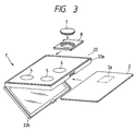
- Fig. 3 shows a second embodiment of the invention in which the structure of the main body case 3 is modified. Only the portions of the second embodiment that are different from the first embodiment will be described.
- a portable communication device 1' in Fig. 3, includes a main body case 22 structured as a holder which can store an IC card 2.
- the main body case 22 includes a card storage portion 22a formed in a rectangular container that is opened from the lower surface and is shallow in depth and a transparent cover portion 22b which is mounted to the card storage portion 22a in such a manner that it is able to open or close the lower surface opening portion of the card storage portion 22a.
- a lock switch 4, an unlock switch 5, a trunk opener switch 6, a battery 7, a cartridge 8, and functional parts necessary for the structure shown in Fig. 1 are all provided on the card storage portion 22a.
- the IC card 2 is stored in the card storage portion 22a of the main body case 22, while the surface of the IC card 2 with the photograph 2b (see Fig. 2) stuck thereon is placed on the transparent cover portion 22b. Since the transparent cover portion 22b is provided in the main body case 22, it is possible to see the photograph and characters provided on the surface of the IC card 2 while the IC card 2 is being stored in the main body case 22, thereby improving the convenience of the IC card 2.
- Figs. 4 and 5 show a third embodiment in which the invention is applied to an automatic financial accounting system operated by remote control. Only the portions of the third embodiment that are different from the previously described first embodiment will be discussed.
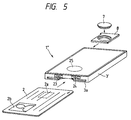
- Fig. 5 shows a portable communication device 1'' and an IC card 2 to be put into the device 1''.
- the portable communication device 1'' has a signal transmitting and receiving function and uses an infrared light as an aerial transmission signal for transmitting and receiving.
- a main body case 3' which is formed as a thin rectangular container, contains a light emitting diode 23 for transmitting an infrared light and a photodiode 24 for receiving the infrared light. Each is located adjacent to a slit 3a for insertion of the IC card 2.
- the upper surface of the main body case 3' includes an operation switch 25 formed from a membrane switch.
- Fig. 4 shows a functional block diagram of the electric structures of the above-mentioned portable communication device 1'' and IC card 2 as well as the electric structure of a signal transmission system using the portable communication device 1'' and IC card 2.
- a battery 7 As shown in Fig. 4, in the main body case 3' of the portable communication device 1, there is only a battery 7, a light emitting diode 23, a photodiode 24, and an operation switch 25.
- a control device also referred to as a transmission control means 26, a cipher device 28, an amplifying device 29, and a receiving means or decoding device 30.
- the control device 26 is composed mainly of a microcomputer. It controls the output level of the battery 7 to the communication device 27, cipher device 28, amplifying device 29, and decoding device 30. It also carries out the following control operations in accordance with the operation of the operation switch 25. Specifically, while the IC card 2 is stored in the main body case 3', the communication device 27, not only supplies power to the IC card 2 but also has access through signal transmitting and receiving means 11 interposed between the control device 26 and decoding device 30 to a control part 9 provided on the IC card 2.
- the cipher device 28 scrambles and ciphers the ID data.
- the cipher device 28 can be implemented by the program of the microcomputer that forms the control device 26.
- the amplifying device 29 combines a ciphered signal containing the ID data to be output from the cipher device 28 with an accounting request operation signal to be output from the control device 26.
- the amplifying device 29 then amplifies the combination signal and applies the amplified combination signal to the light emitting diode 23.
- the light emitting diode 23 transmits the ciphered signal and an infrared light signal containing an operation signal.
- the decoding device 30 decodes the infrared light signal received by the photodiode 24, and applies the decoded signal through the communication device 27 to the IC card 2 to thereby write the same into the memory part 10.
- the control device 26 When the operation switch 25 is activated, the control device 26 generates a request signal to the control part 9 of the IC card 2.
- the IC card 2 requests the control part 9 to answer back the ID data stored in the memory part 10 while the request signal is transmitted through the communication device 27 to the IC card 2 side.
- the control device 26, applies the accounting request operation signal to the amplifying device 28 when the operation switch 25 is operated on. Therefore, in this case, the amplifying device 29 amplifies and outputs the combination signal composed of the accounting request operation signal and the ciphered signal containing the ID data and, in response, the light emitting diode 23 transmits an accounting request signal Sx containing the ciphered ID data in the form of an infrared light signal.
- a transmitting and receiving device 31 for a remote control automatic toll accounting system is installed in a site necessary for toll collection and adjustment, such as a parking lot or a toll gate in a toll road.
- the device 31 includes a photodiode 32, a decoding device 33, a cipher device 34 and a light emitting diode 35.
- the decoding device 33 receives the infrared light signal (the accounting request signal Sx) or other infrared light signal transmitted from the portable communication device 1'', it demodulates the received signal and applies the demodulated signal to a signal processing device or response means 36.
- the signal processing device 36 deciphers the ID data contained in the signal that has been demodulated by the decoding device 33 and collates the deciphered ID data with the previously stored (registered) ID data. When both of the ID data are found identical with each other, the signal processing device 36 determines that it has received the accounting request signal Sx (that is, it has received an accounting instruction) and generates an accounting information signal containing the ID data included in the accounting request signal Sx. It then generates toll information corresponding to this ID data, time information including the data on the year, month, data and time of receipt of the accounting instruction, applies the accounting information signal to the cipher device 34, and stores the accounting information signal into a memory device (not shown) which is used to make up a bill for toll settlement.
- the cipher device 34 scrambles and ciphers the accounting information signal from the signal processing device 36 and applies the ciphered signal to the light emitting diode 35. Responsive to this, the ciphered signal (containing the ID data, toll information and time information) is transmitted as an infrared light signal from the light emitting diode 35.
- the accounting request signal Sx transmitted from the light emitting diode 23 by means of infrared light will be received on the transmitting and receiving device 31.
- the accounting information signal containing the toll information is answered back from the signal processing device 36 by means of infrared light through the light emitting diode 35 and is received by the photodiode 24 on the portable communication device 1''.
- the accounting information signal is demodulated and is then applied to the IC card 2 through the communication device 27.
- the accounting information signal is written into the memory part 10.
- the settlement of the toll information contained in the account information signal will be made later on in accordance with the accounting information signal stored on the signal processing device 36.
- infrared light signal particular to the owner of the IC card 2 can be transmitted by use of the ID data stored in the IC card 2 as well as a function to write the processing data to be answered back according to the transmission of the infrared light signal into the IC card 2.
- An automatic toll accounting system can also be built and then operated by remote control, so that there can be provided similar effects to the first embodiment.
- the card owner does not need to let go of the IC card 2, which advantageously enhances the safety of the IC card 2 against theft.
- the cipher device 28 when the ID data are previously ciphered on the IC card 2 side, the cipher device 28 can be omitted. Also, when code security is not required of the ID data, the ID data need not be ciphered but may be transmitted as they are.
- a portable communication device includes a main body case into which an IC card containing ID data particular to the owner of the IC card can be stored.
- the device also includes operation means controllable from outside, communication means for transmitting and receiving data to and from the stored IC card, and transmission control means, while the operation means is operated on, for transmitting the ID data read out (or the ciphered data of the read-out ID data) from the IC card through the communication means in the form of an aerial propagation signal. Due to this structure, there is no need to perform any processing on the IC card thereby expanding the uses of the card.
- the field of use of the IC card can be expanded and thus the additional value of the IC card can be enhanced by the described signal transmission system since it employs a load control signal for remotely controlling a load is generated by use of the portable communication device having the above-mentioned structure, and since it employs a predetermined processing operation that is executed upon receiving an aerial propagation signal transmitted from the portable communication device.
- the output level of an aerial propagation signal to be transmitted can be increased as well as a longer life for the battery since the device employs a structure in which, on the above-mentioned main body case side, there is provided a battery for supplying power to the IC card while the IC card is stored in the main body case.
- the IC card can be protected since the above-mentioned main body case is structured as a holder for storing the IC card.
Landscapes
- Engineering & Computer Science (AREA)
- Physics & Mathematics (AREA)
- General Physics & Mathematics (AREA)
- Computer Networks & Wireless Communication (AREA)
- Theoretical Computer Science (AREA)
- Business, Economics & Management (AREA)
- Signal Processing (AREA)
- Computer Security & Cryptography (AREA)
- General Business, Economics & Management (AREA)
- Strategic Management (AREA)
- Electromagnetism (AREA)
- Accounting & Taxation (AREA)
- Microelectronics & Electronic Packaging (AREA)
- Finance (AREA)
- Toxicology (AREA)
- General Engineering & Computer Science (AREA)
- Computer Hardware Design (AREA)
- Mechanical Engineering (AREA)
- Health & Medical Sciences (AREA)
- General Health & Medical Sciences (AREA)
- Computing Systems (AREA)
- Artificial Intelligence (AREA)
- Computer Vision & Pattern Recognition (AREA)
- Lock And Its Accessories (AREA)
- Transmitters (AREA)
- Mobile Radio Communication Systems (AREA)
- Optical Communication System (AREA)
Claims (5)
- Système de transmission de signaux, comprenant :une carte à circuit intégré (2) stockant des données d'identification propres au détenteur de la carte à circuit intégré ; etun dispositif de communications portatif possédantun boítier corps principal (3) destiné à recevoir la carte à circuit intégré (2),un moyen d'actionnement (4, 5, 6) placé sur une surface du boítier corps principal ;un moyen de communications sans contact (13, 27) disposé dans le boítier corps principal et servant à lire les données d'identification stockées par la carte à circuit intégré sans qu'il y ait contact avec la carte à circuit intégré ;un moyen de chiffrage (14, 28) servant à chiffrer les données d'identification lues par le moyen de communications sans contact ; etun moyen de commande de transmission (16) disposé dans le boítier corps principal afin de transmettre un signal à propagation aérienne selon un actionnement du moyen d'actionnement, ledit signal à propagation aérienne comportant lesdites données d'identification chiffrées.
- Système de transmission de signaux selon la revendication 1, comprenant en outre :un moyen de réception (16, 24 et 30) disposé dans le boítier corps principal afin de recevoir un signal à propagation aérienne comportant des données de traitement et de stocker les données de traitement dans la carte à circuit intégré via le moyen de communications sans contact (13, 27).
- Système de transmission de signal selon la revendication 1 ou 2, comprenant en outre :un moyen de commande de charge (19, 20, 21) servant à produire un signal de commande de charge lorsque les données d'identification comprises dans le signal à transmission aérienne qui est reçu par un dispositif de réception (18) associé audit moyen de commande de charge, sont identiques à des données d'identification précédemment stockées.
- Système de transmission de signaux selon la revendication précédente, comprenant en outre :une batterie électrique (7) logée dans le boítier corps principal et servant à alimenter électriquement la carte à circuit intégré pendant que la carte à circuit intégré est reçue par le boítier corps principal.
- Système de transmission de signaux selon l'une quelconque des revendications précédentes, où le boítier corps principal comporte une parie interne (3a) destinée à recevoir la carte à circuit intégré.
Applications Claiming Priority (3)
| Application Number | Priority Date | Filing Date | Title |
|---|---|---|---|
| JP6227666A JPH0897777A (ja) | 1994-09-22 | 1994-09-22 | 携帯形通信装置及び信号伝送システム |
| JP22766694 | 1994-09-22 | ||
| JP227666/94 | 1994-09-22 |
Publications (2)
| Publication Number | Publication Date |
|---|---|
| EP0703676A1 EP0703676A1 (fr) | 1996-03-27 |
| EP0703676B1 true EP0703676B1 (fr) | 2000-12-13 |
Family
ID=16864433
Family Applications (1)
| Application Number | Title | Priority Date | Filing Date |
|---|---|---|---|
| EP95114672A Expired - Lifetime EP0703676B1 (fr) | 1994-09-22 | 1995-09-18 | Dispositif de communication portatif et carte à puce associée |
Country Status (5)
| Country | Link |
|---|---|
| EP (1) | EP0703676B1 (fr) |
| JP (1) | JPH0897777A (fr) |
| KR (1) | KR0176989B1 (fr) |
| AU (1) | AU684386B2 (fr) |
| DE (1) | DE69519616T2 (fr) |
Families Citing this family (14)
| Publication number | Priority date | Publication date | Assignee | Title |
|---|---|---|---|---|
| US5796827A (en) * | 1996-11-14 | 1998-08-18 | International Business Machines Corporation | System and method for near-field human-body coupling for encrypted communication with identification cards |
| HU1398U (en) * | 1997-05-14 | 1998-09-28 | Kocsis | Identification terminal for authorization without contact at computerized transaction |
| FR2810435B1 (fr) * | 2000-06-16 | 2003-10-24 | France Telecom | Portefeuille electronique de cartes a puce |
| EP1253559A3 (fr) * | 2001-04-23 | 2005-04-20 | SimonsVoss Technologies AG | Porte-carte et procédé pour combiner la carte d'identification d'entreprise et la fonction clé |
| US20030043095A1 (en) | 2001-08-31 | 2003-03-06 | Kia Silverbrook | Scanning electronic book |
| DE10209015A1 (de) * | 2002-02-25 | 2003-09-18 | Dom Sicherheitstechnik | Zugangskontrollsystem, -anlage und -verfahren |
| WO2004036493A2 (fr) * | 2002-10-14 | 2004-04-29 | Volker Budde | Carte d'acces destinee a controler une autorisation d'acces a un systeme de securite |
| US7406333B2 (en) * | 2002-11-15 | 2008-07-29 | Motorola, Inc. | Method and apparatus for operating a blocked secure storage memory |
| JP3843321B2 (ja) | 2002-11-27 | 2006-11-08 | 独立行政法人産業技術総合研究所 | 情報支援システム |
| US7562219B2 (en) | 2005-04-04 | 2009-07-14 | Research In Motion Limited | Portable smart card reader having secure wireless communications capability |
| EP1916632A1 (fr) * | 2005-04-04 | 2008-04-30 | Research In Motion Limited | Lecteur de carte intelligente portable doté d'une fonctionnalité de communications sans fil sécurisée |
| US7878395B2 (en) | 2005-09-08 | 2011-02-01 | Research In Motion Limited | Alerting a smart card reader of probable wireless communication |
| JP4894350B2 (ja) * | 2006-05-18 | 2012-03-14 | オムロン株式会社 | アクティブ型無線タグ、セキュリティ管理システム、セキュリティ管理方法 |
| US8079068B2 (en) | 2006-07-17 | 2011-12-13 | Research In Motion Limited | Management of multiple connections to a security token access device |
Family Cites Families (4)
| Publication number | Priority date | Publication date | Assignee | Title |
|---|---|---|---|---|
| US4277837A (en) * | 1977-12-30 | 1981-07-07 | International Business Machines Corporation | Personal portable terminal for financial transactions |
| DE3412663A1 (de) * | 1984-04-04 | 1985-10-17 | Siemens AG, 1000 Berlin und 8000 München | Chipkartensystem |
| JPH02235166A (ja) * | 1989-03-09 | 1990-09-18 | Mitsubishi Electric Corp | Icカード応用装置 |
| JPH05300144A (ja) * | 1992-04-16 | 1993-11-12 | Toshiba Corp | 個人通信端末装置 |
-
1994
- 1994-09-22 JP JP6227666A patent/JPH0897777A/ja active Pending
-
1995
- 1995-09-18 DE DE69519616T patent/DE69519616T2/de not_active Expired - Fee Related
- 1995-09-18 EP EP95114672A patent/EP0703676B1/fr not_active Expired - Lifetime
- 1995-09-21 AU AU32806/95A patent/AU684386B2/en not_active Ceased
- 1995-09-22 KR KR1019950032034A patent/KR0176989B1/ko not_active Expired - Fee Related
Also Published As
| Publication number | Publication date |
|---|---|
| AU3280695A (en) | 1996-04-04 |
| KR0176989B1 (ko) | 1999-05-15 |
| JPH0897777A (ja) | 1996-04-12 |
| AU684386B2 (en) | 1997-12-11 |
| EP0703676A1 (fr) | 1996-03-27 |
| KR960012789A (ko) | 1996-04-20 |
| DE69519616D1 (de) | 2001-01-18 |
| DE69519616T2 (de) | 2001-04-12 |
Similar Documents
| Publication | Publication Date | Title |
|---|---|---|
| US7837119B2 (en) | Contactless data carrier | |
| EP0960380B1 (fr) | Dispositif portatif de reconnaissance et de transmission d'empreintes digitales | |
| US6021494A (en) | Electronic micro identification circuit that is inherently bonded to someone or something | |
| AU684386B2 (en) | Portable communication device and signal transmission system | |
| US6142372A (en) | Tractor/trailer having bar code thereon and a GPS receiver for tracking and logging purposes | |
| JPH09303019A (ja) | 識別信号の登録方法及び識別信号の登録装置 | |
| AU4781590A (en) | Secure data interchange system | |
| JP2000159063A (ja) | 車両の利用者を識別する装置 | |
| KR970021600A (ko) | 자동차의 키가 필요없는 원격 엔트리 시스템 및 부동 시스템 | |
| GB2456020A (en) | Secure transaction device and system | |
| EP1282886B1 (fr) | Porte-cartes | |
| JPH0223907B2 (fr) | ||
| US20120176219A1 (en) | Access identification and control device | |
| EP0774737A2 (fr) | Dispositif d'autorisation | |
| US20040049460A1 (en) | Method and device for providing secure of an electronic authorization/credit card | |
| EA001859B1 (ru) | Устройства для регистрации и обработки информации и устройства управления машиной/системой, оборудованной датчиками отпечатков пальцев | |
| JPH1046885A5 (fr) | ||
| JPH0567258A (ja) | Idカード対応型セキユリテイ装置 | |
| JP3683635B2 (ja) | 車両用遠隔操作装置 | |
| KR100653033B1 (ko) | 무선통신 단말기를 이용한 출입 통제 방법 | |
| JP2592827B2 (ja) | 保安システム | |
| KR19990002459A (ko) | 버스무선카드 리더기 | |
| JP4037516B2 (ja) | 自動料金収受システムの不正利用防止装置 | |
| JP3699184B2 (ja) | 車両用遠隔操作装置 | |
| JPH07171014A (ja) | カードケース |
Legal Events
| Date | Code | Title | Description |
|---|---|---|---|
| PUAI | Public reference made under article 153(3) epc to a published international application that has entered the european phase |
Free format text: ORIGINAL CODE: 0009012 |
|
| AK | Designated contracting states |
Kind code of ref document: A1 Designated state(s): DE FR GB IT SE |
|
| 17P | Request for examination filed |
Effective date: 19960703 |
|
| 17Q | First examination report despatched |
Effective date: 19960801 |
|
| RTI1 | Title (correction) |
Free format text: PORTABLE COMMUNICATION DEVICE AND IC CARD THEREFOR |
|
| GRAG | Despatch of communication of intention to grant |
Free format text: ORIGINAL CODE: EPIDOS AGRA |
|
| GRAG | Despatch of communication of intention to grant |
Free format text: ORIGINAL CODE: EPIDOS AGRA |
|
| GRAH | Despatch of communication of intention to grant a patent |
Free format text: ORIGINAL CODE: EPIDOS IGRA |
|
| GRAH | Despatch of communication of intention to grant a patent |
Free format text: ORIGINAL CODE: EPIDOS IGRA |
|
| GRAA | (expected) grant |
Free format text: ORIGINAL CODE: 0009210 |
|
| AK | Designated contracting states |
Kind code of ref document: B1 Designated state(s): DE FR GB IT SE |
|
| PG25 | Lapsed in a contracting state [announced via postgrant information from national office to epo] |
Ref country code: SE Free format text: THE PATENT HAS BEEN ANNULLED BY A DECISION OF A NATIONAL AUTHORITY Effective date: 20001213 Ref country code: IT Free format text: LAPSE BECAUSE OF FAILURE TO SUBMIT A TRANSLATION OF THE DESCRIPTION OR TO PAY THE FEE WITHIN THE PRE;WARNING: LAPSES OF ITALIAN PATENTS WITH EFFECTIVE DATE BEFORE 2007 MAY HAVE OCCURRED AT ANY TIME BEFORE 2007. THE CORRECT EFFECTIVE DATE MAY BE DIFFERENT FROM THE ONE RECORDED.SCRIBED TIME-LIMIT Effective date: 20001213 Ref country code: FR Free format text: LAPSE BECAUSE OF FAILURE TO SUBMIT A TRANSLATION OF THE DESCRIPTION OR TO PAY THE FEE WITHIN THE PRESCRIBED TIME-LIMIT Effective date: 20001213 |
|
| REF | Corresponds to: |
Ref document number: 69519616 Country of ref document: DE Date of ref document: 20010118 |
|
| EN | Fr: translation not filed | ||
| PGFP | Annual fee paid to national office [announced via postgrant information from national office to epo] |
Ref country code: GB Payment date: 20010919 Year of fee payment: 7 |
|
| PGFP | Annual fee paid to national office [announced via postgrant information from national office to epo] |
Ref country code: DE Payment date: 20011001 Year of fee payment: 7 |
|
| PLBE | No opposition filed within time limit |
Free format text: ORIGINAL CODE: 0009261 |
|
| STAA | Information on the status of an ep patent application or granted ep patent |
Free format text: STATUS: NO OPPOSITION FILED WITHIN TIME LIMIT |
|
| 26N | No opposition filed | ||
| REG | Reference to a national code |
Ref country code: GB Ref legal event code: IF02 |
|
| PG25 | Lapsed in a contracting state [announced via postgrant information from national office to epo] |
Ref country code: GB Free format text: LAPSE BECAUSE OF NON-PAYMENT OF DUE FEES Effective date: 20020918 |
|
| PG25 | Lapsed in a contracting state [announced via postgrant information from national office to epo] |
Ref country code: DE Free format text: LAPSE BECAUSE OF NON-PAYMENT OF DUE FEES Effective date: 20030401 |
|
| GBPC | Gb: european patent ceased through non-payment of renewal fee |
Effective date: 20020918 |