EP0703686A2 - Estimation à vraisemblance maximale utilisant les pics de référence et spontanés de la sortie d'un égaliseur à réponse partielle - Google Patents
Estimation à vraisemblance maximale utilisant les pics de référence et spontanés de la sortie d'un égaliseur à réponse partielle Download PDFInfo
- Publication number
- EP0703686A2 EP0703686A2 EP95306779A EP95306779A EP0703686A2 EP 0703686 A2 EP0703686 A2 EP 0703686A2 EP 95306779 A EP95306779 A EP 95306779A EP 95306779 A EP95306779 A EP 95306779A EP 0703686 A2 EP0703686 A2 EP 0703686A2
- Authority
- EP
- European Patent Office
- Prior art keywords
- signal
- predetermined number
- amplitude
- amplitudes
- decision
- Prior art date
- Legal status (The legal status is an assumption and is not a legal conclusion. Google has not performed a legal analysis and makes no representation as to the accuracy of the status listed.)
- Withdrawn
Links
- 238000007476 Maximum Likelihood Methods 0.000 title claims abstract description 22
- 230000004044 response Effects 0.000 title claims abstract description 12
- 230000002269 spontaneous effect Effects 0.000 title description 3
- 230000007704 transition Effects 0.000 claims abstract description 32
- 230000003044 adaptive effect Effects 0.000 claims description 9
- 230000003287 optical effect Effects 0.000 claims description 8
- 238000000034 method Methods 0.000 claims description 5
- 238000010586 diagram Methods 0.000 description 14
- 230000003111 delayed effect Effects 0.000 description 2
- 230000008569 process Effects 0.000 description 2
- 230000006978 adaptation Effects 0.000 description 1
- 238000001514 detection method Methods 0.000 description 1
- 238000000605 extraction Methods 0.000 description 1
- 230000004907 flux Effects 0.000 description 1
- 230000006870 function Effects 0.000 description 1
- 230000004048 modification Effects 0.000 description 1
- 238000012986 modification Methods 0.000 description 1
- 230000011664 signaling Effects 0.000 description 1
- 238000001228 spectrum Methods 0.000 description 1
Images




Classifications
-
- G—PHYSICS
- G11—INFORMATION STORAGE
- G11B—INFORMATION STORAGE BASED ON RELATIVE MOVEMENT BETWEEN RECORD CARRIER AND TRANSDUCER
- G11B20/00—Signal processing not specific to the method of recording or reproducing; Circuits therefor
- G11B20/10—Digital recording or reproducing
- G11B20/10009—Improvement or modification of read or write signals
Definitions
- the present invention relates generally to signal processing using partial response signaling and maximum likelihood estimation, and more specifically to processing of high-density playback signals such as those recorded on optical discs as a series of microscopic pits or those recorded on magnetic mediums using vertical recording techniques.
- equalizers are usually employed to compensate for intersymbol interference to improve the quality of high-density signals extracted from a recording disc.
- microscopic pits produced by a laser beam are closely spaced apart.
- the recording level is not necessarily uniform across the length of the pit due to unequal distribution of optical energies over the length of the pit, and the amplitude a signal extracted therefrom is not uniform. Since this nonuniformity has a nonlinear characteristic and cannot be compensated for by conventional transversal filter equalizers which are implemented with linear circuits and devices.
- Another problem associated with the playback of high-density recorded signals is that, due to the mixed presence of long and short pits which are spaced at very short intervals, the playback signals from short pits have not sufficient energy to reach the saturation levels and their amplitudes vary in a range far short thereof, while the amplitude of those signals read from long pits varies in a range close to the saturation levels.
- Partial response equalization is known for intersymbol interference problems.
- the gain-versus-frequency characreristic of such equalizer produces an output having an emphasized gain at high frequencies. If a maximum likelihood estimation is used in combination with a PR(1,1) equalizer for reproducing high-density signals the amplitude nonuniformity of readout signals and the characteristic high-frequency emphasis of the equalizer would produce a noise which seriously affects the estimation process.
- a signal processor for processing a multilevel signal comprising a partial response equalizer having a first predetermined number of reference amplitudes, the equalizer receiving the multilevel signal and detecting therefrom a significant instant of amplitude transition with respect to the reference amplitudes and producing a signal representative of the amplitude at the detected significant instant, the amplitude representative signal assuming one of a second predetermined number of amplitudes including spontaneously generated amplitudes, the second predetermined number being greater than the first predetermined number of the reference amplitudes.
- a maximum likelihood estimator having transition states and a state transition rule which determines one of the states with respect to decision thresholds greater in number than the first predetermined number and equal to or smaller than the second predetermined number, the estimator receiving the amplitude representative signal from the equalizer and estimating therefrom a maximum likelihood amplitude according to the state transition rule.
- the playback signal processor generally comprises an adaptive equalizer 1, a maximum likelihood estimator 2, and a (1+D) demodulator 3.
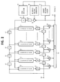
- the adaptive equalizer 1 includes a tapped-delay line filter formed by delay-line elements 11 connected in series to the input terminal 10 to receive the input signal to produce successive tap signals, a plurality of tap-weight multipliers 14 connected respectively to the taps for weighting the tap signals by respective tap weight coefficients C0, C1, Vietnamese , C N supplied from integrators 13 connected respectively to the outputs of correlators 12.
- the weighted tap signals are summed by an adder 15 and supplied to the output terminal 22
- To the output terminal 22 are connected to a ternary decision circuit 17 and an error detector 16. A decision is made in the circuit 17 to determine to which one of reference values -1, 0 and +1 the output of the tapped-delay line filter is closest.
- the decision output is supplied to a reference voltage circuit 18 where the decision output is converted to the corresponding reference value and supplied to the error detector 16, where the difference between the tapped-delay line output is compared with the reference voltage to produce a decision error, which is delayed a unit interval in a delay element 20 and supplied to a gate 21.
- the decision output is further coupled to an edge detector 19 which drives the gate 21 to pass the component of the decision error to the correlators 12 that is generated at each edge of a recorded microscopic pit of the disc or each reversal of a signal vertically recorded on a magnetic recording medium.
- a second tapped-delay line is formed by delay-line taps 11' to receive the input signal and supplies replicas of the tap signals to the correlators 12, respectively. Correlations are taken by the correlators 12 between the replicated tap signals and the error signal.
- the tap-weight coefficients are adaptively controlled with the correlations so that the error power is reduced to a minimum.
- the equalizer 1 By the adaptation control using the three reference amplitude levels -1, 0 and +1, the equalizer 1 produces output voltages that occur at different frequencies with peaks corresponding respectively to the reference amplitudes -1, 0 and +1. In addition to these reference peaks, the equalizer 1 spontaneously produces additional peak components that correspond to -1.5 and +1.5. If the frequency of amplitude occurrences is plotted as a function of the output of the equalizer, there appear three peaks centered respectively on reference amplitudes -1, 0 and +1, as well as two peaks centered respectively on amplitudes -1.5 and +1.5.
- the equalizer 1 produces a total of five distinct amplitude peaks.
- these spontaneously produced peaks do not contribute to the detection of errors since they arise our of phase with significant instants of symbols, i.e., edges of a microscopic pit or reversals of vertically aligned magnetic flux. Therefore, decision errors generated as a result of the spontaneous amplitudes -1.5 and +1.5 are treated as invalid components and rejected by the gate 21.
- the ternary decision circuit 17 includes a pair of comparators C1 and C2 for comparing the tapped-delay line output with two reference voltages set by resistances R9, R10, R11 between DC potentials and produces an output on leads T1, T2.
- the logic states of the leads T1, T2 determine a ternary decision.
- Reference voltage generator 18 is responsive to the logic levels of the decision circuit 17 to produce an output voltage having three reference levels set by resistances R1 to R8.
- Edge detector 19 is also responsive to the logic levels of the output leads of decision circuit 17.
- the gate 21 is turned off to prevent the invalid error components from being supplied to the correlators 12.
- the purpose of the delay unit 20 is to compensate for the time lag of the edge detector 19.
- an equalizer of non-adaptive type can equally be used.
- Such equalizers comprise a tapped delay line, a plurality of tap-weight multipliers connected respectively to the successive taps of the delay line for weighting tap signals on the delay line, and an adder for summing the weighted tap signals.
- a tap-weight memory may be provided for storing the same tap weight coefficients as those obtained by the adaptive equalizer 1 and setting the multipliers to the stored tap weight coefficients.
- the output of the adaptive equalizer 1 is applied to the maximum likelihood estimator 2 which includes a branch metric calculator 4, an add-compare-select circuit 5 and a path memory 6.
- the output of adaptive equalizer 1 is fed into the branch metric calculator 4, where branch metrics B(-1.5), B(-1), B(0), B(+1) and B(+1.5) are calculated corresponding respectively to reference values -1.5, -1, 0, +1 and +1.5 shown in the state transition diagram of Fig. 4 in which equalizer's minimum output spacing corresponding to three transition states, proceeding from S1 to S2, S3, S6 and from S6 to S5, S4, S1, as indicated by broke-line arrows.
- the branch metric calculator 4 has a plurality of subtractors 30 to 34 and squaring circuits 35 to 39 connected to the outputs of corresponding subtractors. Each subtractor and the corresponding squaring circuit form a likelihood estimator for producing a likelihood value B.
- Subtractors 30 to 34 produce difference signals indicating the differences between the equalizer output and the reference amplitudes -1.5, -1, 0, +1 and +1.5. The difference signals are squared respectively in the corresponding squaring circuits 35 to 39, and branch metrics B(-1.5), B(-1), B(0), B(+1) and B(1.5) are produced.
- ACS circuit 5 maintains prcviously obtained path metrics P(S1), P(S2), P(S3), P(S4), P(S5) and P(S6) of the paths respectively entering the states S1, S2, S3, S4, S5 and S6 of the Fig.
- the logic signals U1 and U2 are supplied to the path memory 6 as switching control signals.
- the path memory 6 is made up of a series of switches 40, 41, 42 and 43 interconnected by banks of flip-flops, each successive flip-flop bank being clocked for shifting the outputs of each switching stage to the next.
- Each switch has inputs X1 through X6 and corresponding outputs Y1 through Y6. These X1 to X6 inputs and Y1 to Y6 outputs correspond to transition states S1 to S6, respectively.
- the X inputs and Y outputs are connected according to the state transition diagram of Fig. 4, so that inputs X1, X2, X5 and X6 are permanently connected to outputs Y2, Y3, Y4 and Y5 as indicated by solid lines in Fig. 4.
- the logic level of each of these initial data bits D1 to D6 corresponds to the output value of the corresponding transition state of Fig. 4 as indicated on the left side of each slash marked alongside the corresponding branch.
- the data bits stored in flip-flops 44 are shifted to the next flip-flops 45 through switch 40 and then to flip-flops 46 by way of switch 41.
- the (1+D) demodulator 3 includes a delay element 7 and a modulo-2 adder, or exclusive-OR gate 8.
- the output of the maximum likelihood estimator 2 is applied to the gate 8 through two paths; a delayed path provided through delay element 7 to exclusive-OR gate 8 and a direct path to this gate.
- the exclusive-OR gate 8 combines successive data bits from the estimator and produces a replica of the original data bit stream.
- the equalizer's output spacing may vary with the minimum spacing between successive symbol reversals and pit edges.
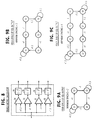
- Fig. 6A shows another possible state transition diagram of the maximum likelihood estimator 2 for the five equalizer output levels in the case of equalizer's minimum output spacing "2" where transitions proceed from state S1 to S2, S4, S3 and in the case of spacing "3" where transitions proceed from state S1 to S2, S6, S4 and from state S4 to S3, S5, S1.
- the state transition diagram of the estimator has eight transition states as shown in Fig. 6B.
- the modified branch metric calculator includes a first decision threshold calculator 50 and a second decision threshold calculator 52 for detecting decision thresholds which appear at other than the predefined values due to channel fluctuations.
- Threshold calculator 50 detects those components of the output of equalizer 1 having amplitude lower than a thresbold ⁇ which lies between -1 and -1.5 and calculates the average value of past amplitudes that appeared over a predefined period. This average value is supplied to the comparator 30 as a lowest decision threshold, instead of the -1.5 decision threshold.
- threshold calculator 52 detects those components of the output of equalizer 1 having amplitude higher than a threshold ⁇ which lies between +1 and +1.5 and calculates the average value of past amplitudes that appeared over the predefined period. This average value is supplied to the comparator 34 as a highest decision threshold, instead of the +1.5 decision threshold.
- the decision thresholds of comparators 30 and 34 are thus adaptively varied to permit the maximum likelihood estimator to adapt to the varying conditions of the channel.
- the branch metric calculator is modified as shown in Fig. 8, which differs from the previous embodiment in that it includes four sets of comparators and squaring circuits corresponding to four reference amplitudes -1.5, -1, +1 and +1.5, respectively.
- the maximum likelihood estimator will have state transition diagrams as shown in Figs. 9A, 9B and 9C for equalizer's minimum output spacings of "2", "3" and "4", respectively.
- the gain-versus-frequency characteristics of the of four- and five-level equalizers of the present invention are favorably compared with the corresponding characteristic of a prior art PR(1,1) equalizer as illustrated in Fig. 10. It is appreciated that the undesired emphasis at high frequencies is advantageously reduced in the present invention. This permits reproduction of recorded signals with an improved signal-to-noise ratio and extraction of high-density signal energies concentrated in the lower frequency region of the spectrum.
- the eye pattern of the five-level equalizer of this invention is illustrated in Fig. 11 for comparison with the eye pattern of the PR(1,1) equalizer. Because of the wider aperture of the present invention than is provided by the prior art, the error rate of the signal processor of this invention is significantly improved.
Landscapes
- Engineering & Computer Science (AREA)
- Signal Processing (AREA)
- Signal Processing For Digital Recording And Reproducing (AREA)
- Optical Recording Or Reproduction (AREA)
- Error Detection And Correction (AREA)
Applications Claiming Priority (4)
| Application Number | Priority Date | Filing Date | Title |
|---|---|---|---|
| JP229254/94 | 1994-09-26 | ||
| JP22925494 | 1994-09-26 | ||
| JP7063428A JP2768296B2 (ja) | 1994-09-26 | 1995-02-27 | 信号処理装置 |
| JP63428/95 | 1995-02-27 |
Publications (2)
| Publication Number | Publication Date |
|---|---|
| EP0703686A2 true EP0703686A2 (fr) | 1996-03-27 |
| EP0703686A3 EP0703686A3 (fr) | 1997-01-22 |
Family
ID=26404549
Family Applications (1)
| Application Number | Title | Priority Date | Filing Date |
|---|---|---|---|
| EP95306779A Withdrawn EP0703686A3 (fr) | 1994-09-26 | 1995-09-26 | Estimation à vraisemblance maximale utilisant les pics de référence et spontanés de la sortie d'un égaliseur à réponse partielle |
Country Status (3)
| Country | Link |
|---|---|
| US (1) | US5604724A (fr) |
| EP (1) | EP0703686A3 (fr) |
| JP (1) | JP2768296B2 (fr) |
Cited By (1)
| Publication number | Priority date | Publication date | Assignee | Title |
|---|---|---|---|---|
| EP0784322A3 (fr) * | 1995-12-22 | 1997-11-26 | Sony Corporation | Appareil de réproduction de signaux numériques et méthode de réproduction pour ceci |
Families Citing this family (27)
| Publication number | Priority date | Publication date | Assignee | Title |
|---|---|---|---|---|
| JPH09128904A (ja) * | 1995-11-01 | 1997-05-16 | Canon Inc | 情報再生装置 |
| US6058099A (en) | 1995-12-29 | 2000-05-02 | Sony Corporation | Disc-shaped information recording medium having offset address information data |
| JP2853671B2 (ja) * | 1996-09-06 | 1999-02-03 | 日本電気株式会社 | 情報検出装置 |
| US7190720B2 (en) * | 2001-07-03 | 2007-03-13 | Zenith Electronics Corporation | Tap weight initializer for an adaptive equalizer |
| JP3266059B2 (ja) * | 1997-07-24 | 2002-03-18 | 日本電気株式会社 | ビタビ検出器および情報検出装置 |
| US6529460B1 (en) * | 1998-01-31 | 2003-03-04 | Seagate Technology Llc | Detection of pulse peak instance and amplitude in a storage drive |
| JP3611472B2 (ja) | 1999-02-02 | 2005-01-19 | 松下電器産業株式会社 | 適応等化回路 |
| US6704903B1 (en) * | 1999-02-19 | 2004-03-09 | Texas Instruments Incorporated | Simplified branch metric and method |
| US6940924B1 (en) * | 2000-08-15 | 2005-09-06 | Agere Systems Inc. | Signal detection based on channel estimation |
| CA2442922A1 (fr) | 2001-04-04 | 2002-10-17 | Quellan, Inc. | Procede et systeme permettant de decoder des signaux multiniveau |
| KR100878521B1 (ko) * | 2002-05-09 | 2009-01-13 | 삼성전자주식회사 | 소프트 출력 발생장치 및 그 방법 |
| US7035361B2 (en) * | 2002-07-15 | 2006-04-25 | Quellan, Inc. | Adaptive noise filtering and equalization for optimal high speed multilevel signal decoding |
| AU2003287628A1 (en) | 2002-11-12 | 2004-06-03 | Quellan, Inc. | High-speed analog-to-digital conversion with improved robustness to timing uncertainty |
| CN100362854C (zh) * | 2003-02-13 | 2008-01-16 | 松下电器产业株式会社 | 固体摄像装置、其驱动方法及使用它的照相机 |
| US7215623B2 (en) * | 2003-02-26 | 2007-05-08 | Matsushita Electric Industrial Co., Ltd. | Reproduction signal processing apparatus |
| US7804760B2 (en) | 2003-08-07 | 2010-09-28 | Quellan, Inc. | Method and system for signal emulation |
| WO2005018134A2 (fr) | 2003-08-07 | 2005-02-24 | Quellan, Inc. | Procede et systeme pour supprimer la diaphonie |
| WO2005024822A1 (fr) * | 2003-09-02 | 2005-03-17 | Matsushita Electric Industrial Co., Ltd. | Processeur de signaux reproduits et procede de traitement de signaux reproduits |
| US7616700B2 (en) | 2003-12-22 | 2009-11-10 | Quellan, Inc. | Method and system for slicing a communication signal |
| KR100896684B1 (ko) * | 2004-01-27 | 2009-05-14 | 삼성전자주식회사 | 수신 성능이 향상된 디지털 방송 송수신 시스템 및 그의신호처리방법 |
| KR100692596B1 (ko) * | 2004-05-06 | 2007-03-13 | 삼성전자주식회사 | 수신 성능이 향상된 디지털 방송 송수신 시스템 및 그의신호처리방법 |
| TWI248274B (en) * | 2004-10-27 | 2006-01-21 | Ic Plus Corp | Look-ahead equalizer and method of determining output of look-ahead equalizer |
| US7725079B2 (en) * | 2004-12-14 | 2010-05-25 | Quellan, Inc. | Method and system for automatic control in an interference cancellation device |
| KR101372361B1 (ko) * | 2006-04-26 | 2014-03-12 | 인터실 아메리카스 엘엘씨 | 통신 채널로부터 복사성 방출을 감소시키기 위한 방법 및 시스템 |
| US8565054B2 (en) | 2006-12-26 | 2013-10-22 | Panasonic Corporation | Optical recording medium, optical recording medium manufacturing method, reproduction signal processing method and evaluation method |
| EP2043102A4 (fr) * | 2006-12-28 | 2011-07-06 | Panasonic Corp | Procede d'evaluation de support d'enregistrement d'informations, support d'enregistrement d'informations, procede de fabrication de support d'enregistrement d'informations, procede de traitement de signal et dispositif de commande d'acces |
| FR2936593B1 (fr) * | 2008-09-26 | 2010-10-15 | Guilbert Express Sa | Generateur d'air chaud |
Family Cites Families (6)
| Publication number | Priority date | Publication date | Assignee | Title |
|---|---|---|---|---|
| US3723649A (en) * | 1971-04-27 | 1973-03-27 | Electronic Image Syst Corp | Adaptive binary state decision system |
| US5010333A (en) * | 1989-05-17 | 1991-04-23 | Halliburton Logging Services, Inc. | Advanced digital telemetry system for monocable transmission featuring multilevel correlative coding and adaptive transversal filter equalizer |
| US5132988A (en) * | 1990-12-03 | 1992-07-21 | Board Of Trustees, Leland Stanford Jr. University | Adaptive decision feedback equalizer apparatus for processing information stored on digital storage media |
| US5233629A (en) * | 1991-07-26 | 1993-08-03 | General Instrument Corporation | Method and apparatus for communicating digital data using trellis coded qam |
| JPH06103696A (ja) * | 1992-09-16 | 1994-04-15 | Hitachi Ltd | データ信号再生装置 |
| US5432818A (en) * | 1993-02-16 | 1995-07-11 | Lou; Yuang | Method and apparatus of joint adaptive channel encoding, adaptive system filtering, and maximum likelihood sequence estimation process by means of an unknown data training |
-
1995
- 1995-02-27 JP JP7063428A patent/JP2768296B2/ja not_active Expired - Lifetime
- 1995-09-26 EP EP95306779A patent/EP0703686A3/fr not_active Withdrawn
- 1995-09-26 US US08/534,210 patent/US5604724A/en not_active Expired - Lifetime
Non-Patent Citations (1)
| Title |
|---|
| None |
Cited By (1)
| Publication number | Priority date | Publication date | Assignee | Title |
|---|---|---|---|---|
| EP0784322A3 (fr) * | 1995-12-22 | 1997-11-26 | Sony Corporation | Appareil de réproduction de signaux numériques et méthode de réproduction pour ceci |
Also Published As
| Publication number | Publication date |
|---|---|
| JP2768296B2 (ja) | 1998-06-25 |
| US5604724A (en) | 1997-02-18 |
| JPH08153370A (ja) | 1996-06-11 |
| EP0703686A3 (fr) | 1997-01-22 |
Similar Documents
| Publication | Publication Date | Title |
|---|---|---|
| EP0703686A2 (fr) | Estimation à vraisemblance maximale utilisant les pics de référence et spontanés de la sortie d'un égaliseur à réponse partielle | |
| JP3638093B2 (ja) | 光ディスクの復号装置 | |
| JP3806219B2 (ja) | 符号間干渉低減装置および方法 | |
| JP3611472B2 (ja) | 適応等化回路 | |
| EP0644661B1 (fr) | Appareil pour traiter des signaux | |
| EP0940811B1 (fr) | Egalisateur de formes d'onde utilisé dans un appareil de reproduction d'information enregistrée | |
| EP0492419B1 (fr) | Système de décodage Viterbi avec équaliseur à ordre variable | |
| US5995561A (en) | Method and apparatus for reducing noise correlation in a partial response channel | |
| EP0808046A2 (fr) | Appareil et méthode de traitement de signaux numériques | |
| US6061395A (en) | Waveform equalizer | |
| Mita et al. | Automatic equalizer for digital magnetic recording systems | |
| JP3428376B2 (ja) | 自動等化システム | |
| US5862157A (en) | Method and circuitry for monitoring a digital channel | |
| WO2001093252A1 (fr) | Signal egalise de lecture a brouillage entre symboles a brouillage cible entre symboles et a reponse partielle contenue | |
| Raghavan et al. | Non-uniformly spaced tapped-delay-line equalizers | |
| JPH07192270A (ja) | 光ディスク信号再生方式 | |
| JP3331818B2 (ja) | ディジタル情報再生装置 | |
| KR100474821B1 (ko) | 비선형특성을갖는재생신호처리장치및방법 | |
| KR100245789B1 (ko) | 램을 이용한 결정 궤한 등화기를 갖는 부분 응답 신호 재생기 | |
| KR100335616B1 (ko) | 데이타저장기기에 있어서신호검출방법및장치 | |
| Bracken et al. | Adaptive continuous-time equalization followed by FDTS/DF sequence detection | |
| JP3428355B2 (ja) | 波形等化回路 | |
| JP4200113B2 (ja) | 等化器および磁気記録再生装置 | |
| Cho et al. | Combining nonlinear equalization and simple detection for high-density optical recording channels | |
| JP3772602B2 (ja) | ディジタル信号再生装置 |
Legal Events
| Date | Code | Title | Description |
|---|---|---|---|
| PUAI | Public reference made under article 153(3) epc to a published international application that has entered the european phase |
Free format text: ORIGINAL CODE: 0009012 |
|
| AK | Designated contracting states |
Kind code of ref document: A2 Designated state(s): FR GB NL |
|
| PUAL | Search report despatched |
Free format text: ORIGINAL CODE: 0009013 |
|
| AK | Designated contracting states |
Kind code of ref document: A3 Designated state(s): FR GB NL |
|
| 17P | Request for examination filed |
Effective date: 19961217 |
|
| 17Q | First examination report despatched |
Effective date: 19970326 |
|
| STAA | Information on the status of an ep patent application or granted ep patent |
Free format text: STATUS: THE APPLICATION IS DEEMED TO BE WITHDRAWN |
|
| 18D | Application deemed to be withdrawn |
Effective date: 20000412 |