EP0704149A2 - Zugdeichsel für Silageentnahme Wagen - Google Patents
Zugdeichsel für Silageentnahme Wagen Download PDFInfo
- Publication number
- EP0704149A2 EP0704149A2 EP95402168A EP95402168A EP0704149A2 EP 0704149 A2 EP0704149 A2 EP 0704149A2 EP 95402168 A EP95402168 A EP 95402168A EP 95402168 A EP95402168 A EP 95402168A EP 0704149 A2 EP0704149 A2 EP 0704149A2
- Authority
- EP
- European Patent Office
- Prior art keywords
- drawbar
- silage
- tractor
- cutter
- unloader
- Prior art date
- Legal status (The legal status is an assumption and is not a legal conclusion. Google has not performed a legal analysis and makes no representation as to the accuracy of the status listed.)
- Withdrawn
Links
- 239000004460 silage Substances 0.000 title claims abstract description 25
- 230000008878 coupling Effects 0.000 description 3
- 238000010168 coupling process Methods 0.000 description 3
- 238000005859 coupling reaction Methods 0.000 description 3
- 238000005070 sampling Methods 0.000 description 2
- 235000016623 Fragaria vesca Nutrition 0.000 description 1
- 240000009088 Fragaria x ananassa Species 0.000 description 1
- 235000011363 Fragaria x ananassa Nutrition 0.000 description 1
- 238000006073 displacement reaction Methods 0.000 description 1
- 239000011435 rock Substances 0.000 description 1
- 239000010902 straw Substances 0.000 description 1
Images
Classifications
-
- A—HUMAN NECESSITIES
- A01—AGRICULTURE; FORESTRY; ANIMAL HUSBANDRY; HUNTING; TRAPPING; FISHING
- A01F—PROCESSING OF HARVESTED PRODUCE; HAY OR STRAW PRESSES; DEVICES FOR STORING AGRICULTURAL OR HORTICULTURAL PRODUCE
- A01F25/00—Storing agricultural or horticultural produce; Hanging-up harvested fruit
- A01F25/16—Arrangements in forage silos
- A01F25/20—Unloading arrangements
- A01F25/2027—Unloading arrangements for trench silos
- A01F2025/2054—Machinery for cutting successive parallel layers of material in a trench silo
Definitions
- the present invention relates to a drawbar for a towed unloader intended to be hooked to a tractor by means of a drawbar of adjustable length.
- the silage cutter is moved back with the tractor until the cutting face of the ensiled part is accessible to the shovel of the silage cutter. Then with the shovel we take one or more slices of ensiled products. At a certain point, the working face is no longer accessible by shovel, so you have to move the trailer either to take slices of ensiled products next to the area of the products which have been removed from the working face, or to go deeper into the face. To do this, for example, reverse the silo wagon with the tractor. It should be noted that in the removal position, so that the shovel or any other member such as a cutter can properly load the bucket, the silage cutter is most often lowered by raising its wheels. For movement, the wheels are lowered to clear the bottom of the silage cutter from the ground and allow it to be moved.
- the object of the present invention is to create a drawbar for towing hitch making it possible to simplify the maneuvers relative to the working face.
- the invention relates to a drawbar coupling drawbar corresponding to the type defined above, characterized in that the drawbar is composed of at least two parts, movable relative to each other, of controlled way to move the silo cutter relative to the fixed part of the drawbar, this part being connected to a fixed point.
- the operator of the silage cutter which is generally installed at the front end of the silage cutter to control its operation, does not have to get down from its control station to move the silage cutter and allow its access to the face.
- the invention relates to a drawbar coupling drawbar.
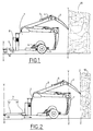
- the silage cutter includes a bucket 1 open at the rear and provided at its rear part with an unloading device formed in the case of the present example by a shovel 2 carried by an arm 3 articulated to the bucket, the shovel 2 being itself articulated on the arm 3.
- the assembly is controlled by at least one jack 4 which rocks the shovel 2 relative to the arm 3. Another jack, not shown, controls the lifting of the arm 3.
- the shovel 2 is placed between two twin arms 3.
- the jack 4 is also generally split.
- the two figures 1 and 2 show the shovel 2 and its support and operating members in a raised position, the end of the teeth of the shovel 2 attacking the cutting face of the silo and a lowered position substantially corresponding to the end of the loading movement of the bucket by the shovel 2.
- the silo unloader also comprises wheels 5, controlled by a jack 6, so as to raise or lower, that is to say to lower the bucket and put it at ground level in order to facilitate its loading or the raise for its movement.
- a turbine 8 which receives the products contained in the bucket and propels them through a chute not shown to distribute them either in the troughs of the barn for ensiled products, or for throw them away in the stable when it is straw used as litter.
- the front of the device is equipped with a telescopic drawbar 9 formed of a part 91 secured to the bucket 1 and of a part 92 telescopically sliding relative to the part 91.
- the part 92 is terminated by an eyelet d hitch 93.
- the working face is marked YY and the ensiled products are marked 10.
- this working face is in the position ZZ represented in FIG. 2.
- the movement telescopic pushes back the part 91 and the bucket 1 as well as all its equipment in the direction of the arrow A by a certain distance appearing by the comparison of FIGS. 1 and 2 to get closer again to the working face now placed in ZZ.
- the backward movement of the device and in particular of the bucket 1 corresponds substantially to the thickness of the working face.
- the actuator not shown, since housed inside the parts 91, 92 of the telescopic drawbar 9, is done from the control station of the silage cutter which is located directly above the fixed part 91 of the boom .
- the operator of the silage cutter can remain at his control station to control the telescopic deployment movement of the drawbar 9 and cause the device to recede to approach the size ZZ front.
- the invention has been described above in the case of a particular example of a silage cutter provided with a shovel with control by jacks and turbine equipment.
- the present invention applies under the same conditions to a silo unloader equipped with another means of taking silage products such as for example a strawberry.
- the drawbar hydraulic cylinder is supplied from the tractor PTO.
- Control by hydraulic means such as cylinders and hydraulic motors can also be replaced by other means.
- the turbine is not essential for the application of the invention.
Landscapes
- Life Sciences & Earth Sciences (AREA)
- Environmental Sciences (AREA)
- Agricultural Machines (AREA)
- Filling Or Emptying Of Bunkers, Hoppers, And Tanks (AREA)
Applications Claiming Priority (2)
| Application Number | Priority Date | Filing Date | Title |
|---|---|---|---|
| FR9411594A FR2724811B1 (fr) | 1994-09-28 | 1994-09-28 | Timon d'attelage pour desileuse tractee |
| FR9411594 | 1994-09-28 |
Publications (2)
| Publication Number | Publication Date |
|---|---|
| EP0704149A2 true EP0704149A2 (de) | 1996-04-03 |
| EP0704149A3 EP0704149A3 (de) | 1996-12-11 |
Family
ID=9467375
Family Applications (1)
| Application Number | Title | Priority Date | Filing Date |
|---|---|---|---|
| EP95402168A Withdrawn EP0704149A3 (de) | 1994-09-28 | 1995-09-27 | Zugdeichsel für Silageentnahme Wagen |
Country Status (2)
| Country | Link |
|---|---|
| EP (1) | EP0704149A3 (de) |
| FR (1) | FR2724811B1 (de) |
Family Cites Families (4)
| Publication number | Priority date | Publication date | Assignee | Title |
|---|---|---|---|---|
| DE2916461A1 (de) * | 1979-02-21 | 1980-11-06 | Windhoff Rheiner Maschf | Mit einem roll- und kratzboden ausgeruesteter futtertransport- und dosierwagen |
| CS265120B1 (en) * | 1987-04-01 | 1989-10-13 | Albrecht Zbynek | Hop harvest conveyer and transport thereof |
| EP0424192A1 (de) * | 1989-09-20 | 1991-04-24 | Etablissements Bugnot | Transportvorrichtung für Rundballen aus Futterpflanzen von einer Presse zu einem Anhänger |
| NL9000208A (nl) * | 1990-01-29 | 1991-08-16 | Zweegers & Zonen P J | Mobiele transportinrichting voor het uit een kuil uitnemen en/of doseren van gewas. |
-
1994
- 1994-09-28 FR FR9411594A patent/FR2724811B1/fr not_active Expired - Fee Related
-
1995
- 1995-09-27 EP EP95402168A patent/EP0704149A3/de not_active Withdrawn
Non-Patent Citations (1)
| Title |
|---|
| None |
Also Published As
| Publication number | Publication date |
|---|---|
| FR2724811B1 (fr) | 1997-01-24 |
| FR2724811A1 (fr) | 1996-03-29 |
| EP0704149A3 (de) | 1996-12-11 |
Similar Documents
| Publication | Publication Date | Title |
|---|---|---|
| EP0511922B1 (de) | Mähmaschine mit schwenkbarer Kupplungsstruktur | |
| EP0552120B1 (de) | Heumaschine mit dynamischer Entlastungsvorrichtung | |
| FR2472536A1 (fr) | Vehicule utilitaire a usages multiples | |
| EP0407322B1 (de) | Entaster | |
| EP0965697A1 (de) | Verfahren und Vorrichtung zum Füllen von Gräben | |
| FR2464624A1 (fr) | Mecanisme de support d'un instrument sur un tracteur ou analogue | |
| FR2724811A1 (fr) | Timon d'attelage pour desileuse tractee | |
| WO1997024025A1 (fr) | Dispositif d'ameublissement du sol | |
| FR2569216A1 (fr) | Dispositif pour le curage, en particulier de saignees perpendiculaires a une voie routiere | |
| FR1405464A (fr) | Perfectionnements aux dispositifs pour creuser des tranchées et analogues | |
| EP1053670B1 (de) | Böschungsmäher | |
| WO2002021898A1 (fr) | Dispositif de relevage pour tracteur permettant d'atteler et de deteler une masse sans intervention manuelle | |
| JP3183955B2 (ja) | コンバイン | |
| EP4066622B1 (de) | Vereinfachte heuwerbungsmaschine mit wagen | |
| FR2860949A1 (fr) | Tondeuse a gazon a recipient collecteur d'herbe | |
| JPS5826289B2 (ja) | コンバインニオケルカリドシヨウコウソウチ | |
| EP0469229B1 (de) | Steuervorrichtung für landwirtschaftiche Maschine und Maschine ausgerüstet mit einer solchen Vorrichtung | |
| FR2491286A1 (fr) | Machine de fenaison pouvant etre accrochee a l'attelage a trois points d'un tracteur et comportant un dispositif pour relever les disques a des hauteurs voisines | |
| FR2621000A1 (fr) | Engin porte-outils modulable | |
| EP0801887A1 (de) | Mähmaschine | |
| FR2519835A1 (fr) | Dispositif d'attelage pour instrument agricole tracte | |
| FR2469300A1 (fr) | Dispositif d'attelage de vehicule | |
| FR2625644A1 (en) | Silo-unloading and dispensing device | |
| BE838165A (fr) | Remorque desileuse tractee | |
| FR2901452A1 (fr) | Machine agricole pouvant etre attelee a l'arriere d'un tracteur par l'intermediaire d'une poutre semi-portee |
Legal Events
| Date | Code | Title | Description |
|---|---|---|---|
| PUAI | Public reference made under article 153(3) epc to a published international application that has entered the european phase |
Free format text: ORIGINAL CODE: 0009012 |
|
| AK | Designated contracting states |
Kind code of ref document: A2 Designated state(s): AT BE CH DE DK ES GB GR IE IT LI LU MC NL PT SE |
|
| PUAL | Search report despatched |
Free format text: ORIGINAL CODE: 0009013 |
|
| AK | Designated contracting states |
Kind code of ref document: A3 Designated state(s): AT BE CH DE DK ES GB GR IE IT LI LU MC NL PT SE |
|
| 17P | Request for examination filed |
Effective date: 19970222 |
|
| 17Q | First examination report despatched |
Effective date: 20000407 |
|
| STAA | Information on the status of an ep patent application or granted ep patent |
Free format text: STATUS: THE APPLICATION IS DEEMED TO BE WITHDRAWN |
|
| 18D | Application deemed to be withdrawn |
Effective date: 20010331 |