EP0965697A1 - Verfahren und Vorrichtung zum Füllen von Gräben - Google Patents
Verfahren und Vorrichtung zum Füllen von Gräben Download PDFInfo
- Publication number
- EP0965697A1 EP0965697A1 EP99401498A EP99401498A EP0965697A1 EP 0965697 A1 EP0965697 A1 EP 0965697A1 EP 99401498 A EP99401498 A EP 99401498A EP 99401498 A EP99401498 A EP 99401498A EP 0965697 A1 EP0965697 A1 EP 0965697A1
- Authority
- EP
- European Patent Office
- Prior art keywords
- chassis
- trench
- conveyor
- hopper
- shovel
- Prior art date
- Legal status (The legal status is an assumption and is not a legal conclusion. Google has not performed a legal analysis and makes no representation as to the accuracy of the status listed.)
- Granted
Links
- 238000000034 method Methods 0.000 title claims description 9
- 239000000463 material Substances 0.000 claims abstract description 27
- 230000002441 reversible effect Effects 0.000 claims abstract description 4
- 230000005484 gravity Effects 0.000 claims abstract description 3
- 238000012216 screening Methods 0.000 claims description 19
- 238000005520 cutting process Methods 0.000 claims description 5
- 238000007599 discharging Methods 0.000 claims 1
- 101000852483 Homo sapiens Interleukin-1 receptor-associated kinase 1 Proteins 0.000 description 3
- 102100036342 Interleukin-1 receptor-associated kinase 1 Human genes 0.000 description 3
- 238000006073 displacement reaction Methods 0.000 description 3
- 239000011324 bead Substances 0.000 description 1
- 230000009194 climbing Effects 0.000 description 1
- 239000000470 constituent Substances 0.000 description 1
- 239000012530 fluid Substances 0.000 description 1
- 210000000056 organ Anatomy 0.000 description 1
- 239000002245 particle Substances 0.000 description 1
- 239000003208 petroleum Substances 0.000 description 1
- 239000002994 raw material Substances 0.000 description 1
Images


Classifications
-
- E—FIXED CONSTRUCTIONS
- E02—HYDRAULIC ENGINEERING; FOUNDATIONS; SOIL SHIFTING
- E02F—DREDGING; SOIL-SHIFTING
- E02F7/00—Equipment for conveying or separating excavated material
- E02F7/02—Conveying equipment mounted on a dredger
-
- E—FIXED CONSTRUCTIONS
- E02—HYDRAULIC ENGINEERING; FOUNDATIONS; SOIL SHIFTING
- E02F—DREDGING; SOIL-SHIFTING
- E02F5/00—Dredgers or soil-shifting machines for special purposes
- E02F5/22—Dredgers or soil-shifting machines for special purposes for making embankments; for back-filling
- E02F5/223—Dredgers or soil-shifting machines for special purposes for making embankments; for back-filling for back-filling
- E02F5/226—Dredgers or soil-shifting machines for special purposes for making embankments; for back-filling for back-filling with means for processing the soil, e.g. screening belts, separators; Padding machines
-
- E—FIXED CONSTRUCTIONS
- E02—HYDRAULIC ENGINEERING; FOUNDATIONS; SOIL SHIFTING
- E02F—DREDGING; SOIL-SHIFTING
- E02F7/00—Equipment for conveying or separating excavated material
- E02F7/06—Delivery chutes or screening plants or mixing plants mounted on dredgers or excavators
-
- E—FIXED CONSTRUCTIONS
- E02—HYDRAULIC ENGINEERING; FOUNDATIONS; SOIL SHIFTING
- E02F—DREDGING; SOIL-SHIFTING
- E02F9/00—Component parts of dredgers or soil-shifting machines, not restricted to one of the kinds covered by groups E02F3/00 - E02F7/00
- E02F9/02—Travelling-gear, e.g. associated with slewing gears
- E02F9/028—Travelling-gear, e.g. associated with slewing gears with arrangements for levelling the machine
Definitions
- the present invention relates to a backfill method a trench and a device for the implementation of this process.
- Such a screening and backfilling device usually includes a hopper to receive materials used for backfilling, a continuous conveyor arranged below the hopper, and a sieve system vibrators fed by the continuous conveyor and intended for fill the trench with successive layers of material having a determined particle size.
- the whole is united a frame, which itself is supported, cantilevered above of the trench to be backfilled, by an arm carrying a tractor or similar device.
- We can thus backfill a trench, possibly by carrying out multiple passes with one device, with different layers of the same material or of grain size materials different.
- the chassis also has the disadvantage of being cantilevered relative to the tractor.
- the invention proposes no longer to use a self-powered backfill system, but a screening and backfilling system towed by a hydraulic excavator of a conventional type, which ensures in addition to loading the device with backfill material screening, the hydraulic excavator-device assembly screen can move as well on the cord cuttings from the trench, only on a track laid out the other side of it.
- the invention therefore has for first object a method of backfilling a trench, in particular using spoil from the digging of this trench, this process of towing with a shovel hydraulic, parallel to the trench, a chassis mounted on wheels or on tracks, supporting a hopper of load equipped with a grid at its lower part, load this hopper with backfill using the hydraulic shovel, to transfer the material by gravity backfill through the grid on a vibrating screen placed below the hopper, then on a conveyor continuous, placed below the vibrating screen on the chassis, transverse to its direction of movement, the sieve vibrating and the conveyor being driven by means motors carried by the chassis, and to pour the material out laterally filling in the trench using the conveyor.
- the link with the hydraulic excavator can be a simple drawbar articulated at one end on the chassis and its other end on the hydraulic shovel.
- the hopper is preferably pivotally mounted relative to to the chassis, at least one cylinder being provided on the chassis to straighten it by pivoting relative to it, in view of removing the largest constituents of the material backfill not passing through the grid.
- This can be made up of simple bars arranged in parallel, for example parallel to the direction of movement of the device.
- the conveyor it is preferably arranged transversely to the direction of movement of the chassis, under the stress of the hydraulic shovel which it is made united.
- This conveyor is advantageously mobile in translation under the stress of a double-acting cylinder, so that it can protrude at will as well from left side than the right side of the device. He is by elsewhere driven by at least one reversible motor, by example a hydraulic motor, so that you can dump the backfill material to the right or left of the device.
- the invention finally relates to a backfill assembly a trench, characterized in that it comprises a shovel hydraulic and a screening and dumping device a backfill material of the type which has just been defined, this device being integral in displacement of the shovel hydraulic by a connecting member such as a drawbar, so that it can be towed by the shovel.
- the chassis of the screening device will include at each of its ends means allowing to make it integral in displacement of the shovel hydraulic, so that it can be towed by one or the other of its ends.
- the self-propelled hydraulic excavator is designated by the reference 1
- the device screening and backfilling towed by this excavator is designated by reference 2.
- the shovel 1 can be of any known type.
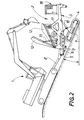
- the device 2 comprises a chassis 3, mounted here on tracks 4, but which could as well be carried by wheels, on which is articulated, by levers 5 and 6, a drawbar 8 articulated at its other end on the chassis of the shovel 1.
- the lever 6 is attacked by the rod of a jack 7 carried by the chassis 3 of the screening and backfilling device.
- This chassis 3 is linked to the structure 9 carrying the tracks 4 by a system of levers such as 10, actuated by a cylinder 11, so as to be able to maintain the chassis in a horizontal position whatever the slope of the ground on which the tracks 4.
- a hopper 12 one end of which adjoins the shovel 1 is pivotally mounted relative to the chassis 3 under the actuation of jacks 13, receives from shovel 1 the raw materials for backfilling the trench 14 (see Figure 4), for example to bury in this cut a tube 15 which is housed there.
- the hopper 12 has a bottom part constituted by a grid 16, here made up of bars parallel arranged longitudinally and intended to retain excessively large cuttings, which can then be removed by lifting the hopper (see figure 2).
- the material passing through this grid falls on a vibrating screen 19, placed below the latter, then on a continuous conveyor 17, carried by the chassis 3 below of the vibrating screen and arranged transversely to the direction of movement thereof.
- This conveyor 17 projects laterally with respect to the chassis above the trench 14 and pours into it backfill materials.
- the conveyor 17 is driven by two reversible hydraulic motors carried by the chassis 3. As indicated above, it can also be moved transversely using a double-acting cylinder, in order to ability to project sideways on one side or the other from the chassis, so that the material can be filling both right and left of it.
- the various cylinders of the screening and backfill and the conveyor drive motors 17 and vibrating screen are fed and operated from a hydraulic cabinet 18 carried by the chassis 3. All of these organs are remotely controlled by a remote control placed in the excavator cabin or operated by an operator near the wiring device.
- the invention therefore provides a simple and inexpensive to backfill trenches, since the device used for backfilling is not self-propelled, but is towed by a hydraulic shovel, which has also for the function of supplying the backfilling with backfill material.
- the two ends of the chassis 3 are substantially identical, so that the screening device 2 integral in displacement of the hydraulic excavator 1 by one or other of these ends.
- the tracks of the screening and backfilling device can adapt to very uneven terrain and move forward for example on the cut bead 20 from trench 14 or on a runway 21 provided on the other side of this trench.
- the hydraulic excavator-screening and backfilling is suitable for climbing or descending slopes relatively sharp, up to 25 °.
Landscapes
- Engineering & Computer Science (AREA)
- Mining & Mineral Resources (AREA)
- Civil Engineering (AREA)
- General Engineering & Computer Science (AREA)
- Structural Engineering (AREA)
- Mechanical Engineering (AREA)
- Combined Means For Separation Of Solids (AREA)
- Investigation Of Foundation Soil And Reinforcement Of Foundation Soil By Compacting Or Drainage (AREA)
- Machines For Laying And Maintaining Railways (AREA)
Applications Claiming Priority (2)
| Application Number | Priority Date | Filing Date | Title |
|---|---|---|---|
| FR9807770A FR2780079B1 (fr) | 1998-06-19 | 1998-06-19 | Procede et dispositif de remblayage d'une tranchee |
| FR9807770 | 1998-06-19 |
Publications (2)
| Publication Number | Publication Date |
|---|---|
| EP0965697A1 true EP0965697A1 (de) | 1999-12-22 |
| EP0965697B1 EP0965697B1 (de) | 2003-10-15 |
Family
ID=9527609
Family Applications (1)
| Application Number | Title | Priority Date | Filing Date |
|---|---|---|---|
| EP99401498A Expired - Lifetime EP0965697B1 (de) | 1998-06-19 | 1999-06-17 | Verfahren und Vorrichtung zum Füllen von Gräben |
Country Status (7)
| Country | Link |
|---|---|
| EP (1) | EP0965697B1 (de) |
| AU (1) | AU747651B2 (de) |
| CA (1) | CA2275067A1 (de) |
| DE (1) | DE69912026T2 (de) |
| ES (1) | ES2209353T3 (de) |
| FR (1) | FR2780079B1 (de) |
| PT (1) | PT965697E (de) |
Cited By (4)
| Publication number | Priority date | Publication date | Assignee | Title |
|---|---|---|---|---|
| WO2004026478A3 (en) * | 2002-09-17 | 2004-11-18 | Jr Robert Richard Rossi | Mobile impact crusher assembly |
| GB2405394A (en) * | 2003-08-29 | 2005-03-02 | Kevin Gates | A material handling apparatus comprising a conveyor |
| US6871807B2 (en) | 2002-09-17 | 2005-03-29 | Robert R. Rossi, Jr. | Mobile impact crusher assembly |
| US6915972B2 (en) | 2002-09-17 | 2005-07-12 | Robert R. Rossi, Jr. | Mobile jaw crusher assembly |
Families Citing this family (5)
| Publication number | Priority date | Publication date | Assignee | Title |
|---|---|---|---|---|
| AU2003269608B2 (en) * | 2002-11-28 | 2007-08-02 | Mitchell Australasia Pty Ltd. | Trench forming and preparing apparatus |
| GB2412936B (en) * | 2002-11-28 | 2006-06-21 | Mitchell Australasia Pty Ltd | Trench forming and preparing apparatus |
| AU2002952972A0 (en) * | 2002-11-28 | 2002-12-12 | Mitchell Australasia Pty Ltd | Trench forming and preparing apparatus |
| DE102018201077B3 (de) | 2018-01-24 | 2019-05-16 | HGS Hirschfelder Greifer- und Stahlbau GmbH | Vorrichtung für ein profilgesteuertes Einsanden und Verfüllen von Rohrleitungs- und Kabelgräben |
| CN114922242B (zh) * | 2022-05-26 | 2024-06-21 | 利高实业(广州)有限公司 | 一种建筑施工用地基填埋装置 |
Citations (7)
| Publication number | Priority date | Publication date | Assignee | Title |
|---|---|---|---|---|
| FR1347882A (fr) * | 1962-11-23 | 1964-01-04 | Procédé de construction routière et dispositif servant à sa mise en oeuvre | |
| US3701422A (en) * | 1970-05-21 | 1972-10-31 | Zurn Eng | Vehicle mounted earth separating and conveying system |
| US4322178A (en) * | 1980-02-29 | 1982-03-30 | Lee Billy R | Pavement patching apparatus |
| DE3510597A1 (de) * | 1985-03-23 | 1986-10-09 | Hannes-Jürgen 3000 Hannover Kapuschinski | Siebvorrichtung fuer bagger- und radladerbeschickung |
| EP0334143A1 (de) * | 1988-03-23 | 1989-09-27 | KLEEMANN + REINER MASCHINEN- UND ANLAGENBAU VERTRIEBS GmbH | Gerät zum Zerkleinern von Material, insbesondere Gestein sowie Bau- und Strassenbaumaterial |
| EP0367207A1 (de) * | 1988-11-03 | 1990-05-09 | Hannes-Jürgen Kapuschinski | Siebvorrichtung |
| WO1997041971A1 (en) * | 1996-05-03 | 1997-11-13 | Douglas Patrick J | Self-propelled material-processing apparatus |
Family Cites Families (2)
| Publication number | Priority date | Publication date | Assignee | Title |
|---|---|---|---|---|
| US4861461A (en) * | 1987-06-08 | 1989-08-29 | Utterback Eugene C | Pipeline padding machine and method |
| FR2726304B1 (fr) * | 1994-10-31 | 1997-01-17 | Somico | Perfectionnements aux dispositifs de remblayage d'une tranchee, notamment d'une tranchee dans laquelle est logee une conduite de transport d'un fluide |
-
1998
- 1998-06-19 FR FR9807770A patent/FR2780079B1/fr not_active Expired - Fee Related
-
1999
- 1999-06-17 ES ES99401498T patent/ES2209353T3/es not_active Expired - Lifetime
- 1999-06-17 CA CA 2275067 patent/CA2275067A1/en not_active Abandoned
- 1999-06-17 DE DE69912026T patent/DE69912026T2/de not_active Expired - Lifetime
- 1999-06-17 EP EP99401498A patent/EP0965697B1/de not_active Expired - Lifetime
- 1999-06-17 PT PT99401498T patent/PT965697E/pt unknown
- 1999-06-18 AU AU35745/99A patent/AU747651B2/en not_active Ceased
Patent Citations (7)
| Publication number | Priority date | Publication date | Assignee | Title |
|---|---|---|---|---|
| FR1347882A (fr) * | 1962-11-23 | 1964-01-04 | Procédé de construction routière et dispositif servant à sa mise en oeuvre | |
| US3701422A (en) * | 1970-05-21 | 1972-10-31 | Zurn Eng | Vehicle mounted earth separating and conveying system |
| US4322178A (en) * | 1980-02-29 | 1982-03-30 | Lee Billy R | Pavement patching apparatus |
| DE3510597A1 (de) * | 1985-03-23 | 1986-10-09 | Hannes-Jürgen 3000 Hannover Kapuschinski | Siebvorrichtung fuer bagger- und radladerbeschickung |
| EP0334143A1 (de) * | 1988-03-23 | 1989-09-27 | KLEEMANN + REINER MASCHINEN- UND ANLAGENBAU VERTRIEBS GmbH | Gerät zum Zerkleinern von Material, insbesondere Gestein sowie Bau- und Strassenbaumaterial |
| EP0367207A1 (de) * | 1988-11-03 | 1990-05-09 | Hannes-Jürgen Kapuschinski | Siebvorrichtung |
| WO1997041971A1 (en) * | 1996-05-03 | 1997-11-13 | Douglas Patrick J | Self-propelled material-processing apparatus |
Cited By (4)
| Publication number | Priority date | Publication date | Assignee | Title |
|---|---|---|---|---|
| WO2004026478A3 (en) * | 2002-09-17 | 2004-11-18 | Jr Robert Richard Rossi | Mobile impact crusher assembly |
| US6871807B2 (en) | 2002-09-17 | 2005-03-29 | Robert R. Rossi, Jr. | Mobile impact crusher assembly |
| US6915972B2 (en) | 2002-09-17 | 2005-07-12 | Robert R. Rossi, Jr. | Mobile jaw crusher assembly |
| GB2405394A (en) * | 2003-08-29 | 2005-03-02 | Kevin Gates | A material handling apparatus comprising a conveyor |
Also Published As
| Publication number | Publication date |
|---|---|
| AU3574599A (en) | 2000-01-06 |
| FR2780079B1 (fr) | 2000-09-08 |
| AU747651B2 (en) | 2002-05-16 |
| FR2780079A1 (fr) | 1999-12-24 |
| ES2209353T3 (es) | 2004-06-16 |
| EP0965697B1 (de) | 2003-10-15 |
| DE69912026T2 (de) | 2004-07-15 |
| DE69912026D1 (de) | 2003-11-20 |
| PT965697E (pt) | 2004-03-31 |
| CA2275067A1 (en) | 1999-12-19 |
Similar Documents
| Publication | Publication Date | Title |
|---|---|---|
| EP0251876B1 (de) | Mechanisierte Anordnung zum Ausheben eines Grabens und Verlegen von langgestreckten Gegenständen | |
| FR2566020A1 (fr) | Station mobile autonome de concassage | |
| EP0965697B1 (de) | Verfahren und Vorrichtung zum Füllen von Gräben | |
| HU223214B1 (hu) | Eljárás csővezeték alatti tér kitermelt talaj felhasználásával történő kitömésére, eszköz az eljárás foganatosítására, berendezés csővezeték alatti talaj tömörítésére, továbbá talajtömörítő szerkezet | |
| EP2239377A1 (de) | Motorisierte Maschine um in den Boden einen Graben zu schneiden und um in diesen Graben lange Objekte zu legen. | |
| FR2491992A1 (fr) | Machine d'abattage et de chargement continus pour l'exploitation d'une mine souterraine de minerai metallique en roche dure | |
| EP0014154A1 (de) | Von Zugmaschinen gezogene Vorrichtung zum Aufnehmen und Transportieren von Materialien | |
| EP0524299B1 (de) | Gerät zur sicherstellung der aufnahme und der lagerung von gras oder dergleichen und mit einem solchen gerät ausgerüstete fahrzeuge | |
| US2903803A (en) | Log handling apparatus | |
| FR2722809A1 (fr) | Vehicule pour recouvrir des objets allonges a enfouir | |
| US5864971A (en) | Debris removing apparatus | |
| FR2726304A1 (fr) | Perfectionnements aux dispositifs de remblayage d'une tranchee, notamment d'une tranchee dans laquelle est logee une conduite de transport d'un fluide | |
| FR2539157A1 (fr) | Trancheuse a fleche | |
| FR3121691A1 (fr) | Trancheuse pourvue d’un dispositif de creusage et d’un tapis transversal ajustable. | |
| EP0197833A1 (de) | Baumaschine des Schürfkübelbaggerlader-Typs | |
| WO2006027520A1 (fr) | Dispositif automoteur compacteur de dechets | |
| FR2714920A1 (fr) | Machine autochargeuse pour le remblayage de tranchées. | |
| EP0887474A2 (de) | Kabelbetätigte Grabvorrichtung | |
| FR2634347A1 (fr) | Dispositif de prelevement pour separer et ramasser du fourrage | |
| FR2695667A1 (fr) | Machine pour réaliser une tranchée de drainage dans un terrain. | |
| FR2542568A1 (fr) | Broyeur-recuperateur de produits forestiers | |
| AU707344B2 (en) | Debris removing apparatus | |
| BE854060A (fr) | Appareil automoteur pour le nettoyage des betteraves | |
| JPH0537015U (ja) | 堀起し兼用ピツクアツプ装置 | |
| FR2543989A1 (fr) | Dispositif support d'avancement pour machine de terrassement |
Legal Events
| Date | Code | Title | Description |
|---|---|---|---|
| PUAI | Public reference made under article 153(3) epc to a published international application that has entered the european phase |
Free format text: ORIGINAL CODE: 0009012 |
|
| AK | Designated contracting states |
Kind code of ref document: A1 Designated state(s): BE CH DE ES GB IT LI NL PT |
|
| AX | Request for extension of the european patent |
Free format text: AL;LT;LV;MK;RO;SI |
|
| 17P | Request for examination filed |
Effective date: 20000207 |
|
| AKX | Designation fees paid |
Free format text: BE CH DE ES GB IT LI NL PT |
|
| 17Q | First examination report despatched |
Effective date: 20021010 |
|
| GRAH | Despatch of communication of intention to grant a patent |
Free format text: ORIGINAL CODE: EPIDOS IGRA |
|
| GRAS | Grant fee paid |
Free format text: ORIGINAL CODE: EPIDOSNIGR3 |
|
| GRAA | (expected) grant |
Free format text: ORIGINAL CODE: 0009210 |
|
| AK | Designated contracting states |
Kind code of ref document: B1 Designated state(s): BE CH DE ES GB IT LI NL PT |
|
| REG | Reference to a national code |
Ref country code: GB Ref legal event code: FG4D Free format text: NOT ENGLISH Ref country code: CH Ref legal event code: EP |
|
| BECA | Be: change of holder's address |
Owner name: LOC. SPIGAROLO, I-43011 BUSSETO(IT) Effective date: 20031015 Owner name: LAURINI *LODOVICO & C. SNCD-929, F-60530 NEUILLY E Effective date: 20031015 Owner name: SOC. *MINIERE ET COMMERCIALE Effective date: 20031015 |
|
| REF | Corresponds to: |
Ref document number: 69912026 Country of ref document: DE Date of ref document: 20031120 Kind code of ref document: P |
|
| RAP2 | Party data changed (patent owner data changed or rights of a patent transferred) |
Owner name: LAURINI LODOVICO & C. SNC Owner name: SOCIETE MINIERE ET COMMERCIALE |
|
| GBT | Gb: translation of ep patent filed (gb section 77(6)(a)/1977) |
Effective date: 20040128 |
|
| NLT2 | Nl: modifications (of names), taken from the european patent patent bulletin |
Owner name: SOCIETE MINIERE ET COMMERCIALE EN LAURINI LODOVICO |
|
| REG | Reference to a national code |
Ref country code: PT Ref legal event code: SC4A Free format text: AVAILABILITY OF NATIONAL TRANSLATION Effective date: 20040113 |
|
| REG | Reference to a national code |
Ref country code: ES Ref legal event code: FG2A Ref document number: 2209353 Country of ref document: ES Kind code of ref document: T3 |
|
| PLBE | No opposition filed within time limit |
Free format text: ORIGINAL CODE: 0009261 |
|
| STAA | Information on the status of an ep patent application or granted ep patent |
Free format text: STATUS: NO OPPOSITION FILED WITHIN TIME LIMIT |
|
| 26N | No opposition filed |
Effective date: 20040716 |
|
| PGFP | Annual fee paid to national office [announced via postgrant information from national office to epo] |
Ref country code: CH Payment date: 20050623 Year of fee payment: 7 |
|
| PGFP | Annual fee paid to national office [announced via postgrant information from national office to epo] |
Ref country code: BE Payment date: 20050628 Year of fee payment: 7 |
|
| PG25 | Lapsed in a contracting state [announced via postgrant information from national office to epo] |
Ref country code: LI Free format text: LAPSE BECAUSE OF NON-PAYMENT OF DUE FEES Effective date: 20060630 Ref country code: CH Free format text: LAPSE BECAUSE OF NON-PAYMENT OF DUE FEES Effective date: 20060630 Ref country code: BE Free format text: LAPSE BECAUSE OF NON-PAYMENT OF DUE FEES Effective date: 20060630 |
|
| REG | Reference to a national code |
Ref country code: CH Ref legal event code: PL |
|
| BERE | Be: lapsed |
Owner name: LAURINI *LODOVICO & C. SNC Effective date: 20060630 Owner name: SOC. *MINIERE ET COMMERCIALE Effective date: 20060630 |
|
| PGFP | Annual fee paid to national office [announced via postgrant information from national office to epo] |
Ref country code: ES Payment date: 20110624 Year of fee payment: 13 Ref country code: PT Payment date: 20110615 Year of fee payment: 13 |
|
| PGFP | Annual fee paid to national office [announced via postgrant information from national office to epo] |
Ref country code: GB Payment date: 20110620 Year of fee payment: 13 Ref country code: NL Payment date: 20110621 Year of fee payment: 13 |
|
| PGFP | Annual fee paid to national office [announced via postgrant information from national office to epo] |
Ref country code: DE Payment date: 20110622 Year of fee payment: 13 |
|
| PGFP | Annual fee paid to national office [announced via postgrant information from national office to epo] |
Ref country code: IT Payment date: 20110624 Year of fee payment: 13 |
|
| REG | Reference to a national code |
Ref country code: PT Ref legal event code: MM4A Free format text: LAPSE DUE TO NON-PAYMENT OF FEES Effective date: 20121217 |
|
| REG | Reference to a national code |
Ref country code: NL Ref legal event code: V1 Effective date: 20130101 |
|
| GBPC | Gb: european patent ceased through non-payment of renewal fee |
Effective date: 20120617 |
|
| PG25 | Lapsed in a contracting state [announced via postgrant information from national office to epo] |
Ref country code: PT Free format text: LAPSE BECAUSE OF NON-PAYMENT OF DUE FEES Effective date: 20121217 Ref country code: IT Free format text: LAPSE BECAUSE OF NON-PAYMENT OF DUE FEES Effective date: 20120617 |
|
| REG | Reference to a national code |
Ref country code: DE Ref legal event code: R119 Ref document number: 69912026 Country of ref document: DE Effective date: 20130101 |
|
| PG25 | Lapsed in a contracting state [announced via postgrant information from national office to epo] |
Ref country code: GB Free format text: LAPSE BECAUSE OF NON-PAYMENT OF DUE FEES Effective date: 20120617 Ref country code: DE Free format text: LAPSE BECAUSE OF NON-PAYMENT OF DUE FEES Effective date: 20130101 Ref country code: NL Free format text: LAPSE BECAUSE OF NON-PAYMENT OF DUE FEES Effective date: 20130101 |
|
| REG | Reference to a national code |
Ref country code: ES Ref legal event code: FD2A Effective date: 20131022 |
|
| PG25 | Lapsed in a contracting state [announced via postgrant information from national office to epo] |
Ref country code: ES Free format text: LAPSE BECAUSE OF NON-PAYMENT OF DUE FEES Effective date: 20120618 |