EP0704155A2 - Auswurfkrümmer für Silagefräse - Google Patents
Auswurfkrümmer für Silagefräse Download PDFInfo
- Publication number
- EP0704155A2 EP0704155A2 EP95402167A EP95402167A EP0704155A2 EP 0704155 A2 EP0704155 A2 EP 0704155A2 EP 95402167 A EP95402167 A EP 95402167A EP 95402167 A EP95402167 A EP 95402167A EP 0704155 A2 EP0704155 A2 EP 0704155A2
- Authority
- EP
- European Patent Office
- Prior art keywords
- chute
- articulated
- mobile
- fixed
- telescopic
- Prior art date
- Legal status (The legal status is an assumption and is not a legal conclusion. Google has not performed a legal analysis and makes no representation as to the accuracy of the status listed.)
- Withdrawn
Links
- 239000004460 silage Substances 0.000 title claims description 9
- 241000238565 lobster Species 0.000 description 1
- 239000010902 straw Substances 0.000 description 1
Images

Classifications
-
- A—HUMAN NECESSITIES
- A01—AGRICULTURE; FORESTRY; ANIMAL HUSBANDRY; HUNTING; TRAPPING; FISHING
- A01K—ANIMAL HUSBANDRY; AVICULTURE; APICULTURE; PISCICULTURE; FISHING; REARING OR BREEDING ANIMALS, NOT OTHERWISE PROVIDED FOR; NEW BREEDS OF ANIMALS
- A01K5/00—Feeding devices for stock or game ; Feeding wagons; Feeding stacks
- A01K5/001—Fodder distributors with mixer or shredder
- A01K5/005—Fodder distributors with mixer or shredder where fodder, e.g. bales, is conveyed by conveyor or slide to mixing or shredding elements on transversal and horizontal axes
-
- A—HUMAN NECESSITIES
- A01—AGRICULTURE; FORESTRY; ANIMAL HUSBANDRY; HUNTING; TRAPPING; FISHING
- A01F—PROCESSING OF HARVESTED PRODUCE; HAY OR STRAW PRESSES; DEVICES FOR STORING AGRICULTURAL OR HORTICULTURAL PRODUCE
- A01F25/00—Storing agricultural or horticultural produce; Hanging-up harvested fruit
- A01F25/16—Arrangements in forage silos
- A01F25/20—Unloading arrangements
- A01F25/2027—Unloading arrangements for trench silos
-
- A—HUMAN NECESSITIES
- A01—AGRICULTURE; FORESTRY; ANIMAL HUSBANDRY; HUNTING; TRAPPING; FISHING
- A01F—PROCESSING OF HARVESTED PRODUCE; HAY OR STRAW PRESSES; DEVICES FOR STORING AGRICULTURAL OR HORTICULTURAL PRODUCE
- A01F29/00—Cutting apparatus specially adapted for cutting hay, straw or the like
- A01F29/005—Cutting apparatus specially adapted for cutting hay, straw or the like for disintegrating and cutting up bales of hay, straw or fodder
Definitions
- the present invention relates to an articulated silage chute comprising a rotation base around which the chute can pivot around a vertical axis, and carrying a fixed chute element.
- This articulated chute is mounted on a rotation base.
- the chute itself which pivots around the axis of this base, is formed of U-section elements, articulated to each other and constituting a deformable chute, in the manner of a lobster tail.
- the end of the last element is connected to a pivoting arm controlled by a jack.
- the pivoting of this arm makes it possible to modify the curvature of the chute thus formed to produce a chute with a very small radius of curvature, to deposit the products leaving the chute near the chute, or with a large radius of curvature, to project at away the products coming out of the chute.
- Such an articulated chute has the disadvantage, by the very fact of its structure, of being very short so that it does not have good directivity which is very annoying for remote projection.
- the present invention aims to remedy these drawbacks and proposes to create an articulated chute, in particular intended for silage cutters, for deviating or directing products of very different nature such as pieces of straw, that is to say, very dry and non-sticky products or silage products which are by nature soft and often sticky, so as to avoid any stuffing or clogging of the chute during work while ensuring excellent directivity both near and at a distance.
- the articulated chute according to the invention has the advantage of being made up of an extremely simple telescopic structure, with one or possibly two elements relative to each other. This telescopic connection allows a controlled sliding of the mobile element relative to the fixed element, giving a precise directivity of the product jet.
- the telescopic movement also makes it possible to shorten the articulated chute as much as possible, for example to put it in the transport position.
- the end of the movable element of the chute comprises an additional element or cap, playing the role of deflector to precisely direct the products at the outlet of the chute.
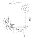
- the invention relates to an articulated chute in the form of a telescopic chute 1 fitted to a silage unloader.
- This silage cutter itself consists of a bucket 2 carried by wheels 3, which can be lifted.
- the rear end of the bucket can be fitted with a loading device which enables products to be taken from a silo to load the bucket 2.
- This end of the bucket 1 is open.
- the other end of the closed bucket is equipped with a turbine 5 which receives the products from the bucket conveyed for example by a conveyor belt constituting the bottom of the bucket 2.
- the turbine projects the products through the chute 1.
- This chute can pivot around its vertical axis XX and extend telescopically to change its curvature and direct the jet of products at will not only in orientation around the axis XX but also in distance.
- the telescopic chute 1 In the position shown in Figure 1, the telescopic chute 1 is shown folded, and located in the plane of symmetry of the apparatus, that is to say the plane parallel to that of FIG. 1.
- the chute 1 consists of a base 11 constituted for example by a ball ring around which the chute 1 itself can pivot.
- This base integrally carries a fixed part 12 (that is to say only rotatable around the base) of a chute as well as two lateral arms 13.
- These lateral arms 13 carry, by means of connecting rods 14, the second part 15 chute or moving part.
- This mobile part 15 is connected to the connecting rod 14 in particular by the articulation 16.
- the mobile part 15 of the chute 1 is also guided relative to the fixed part (hidden in FIG. 1) by a slide 17 located on each side and cooperating with a roller 18 carried by the fixed part 12.
- a jack 19 connected on the one hand to the fixed part 12 by means not shown and, on the other hand, to the articulation 16, controls the telescopic movement of the mobile part 15.
- the movable part 15 includes a deflector or cap 20 pivotally mounted and controlled in its pivoting movement by a jack 21.
- This deflector 20 articulated and orientable at the end of the movable part 15 constitutes another means of orientation of the jet of products.
- Figure 1 shows the chute 1 in the folded position while Figure 2 shows it in the deployed position. In this position, the mobile part 15 is fully deployed and extends the fixed part 12.
- the deflector 20 is folded down but it could also be placed in the extension of the mobile part 15.
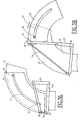
- FIGS 3A, 3B schematically show the principle of the invention.
- the fixed part 12 is also carried by a base 11 connected to the part of the turbine casing, not shown.
- the chute also comprises a movable part 15 connected to the fixed part 12 as has been described, on the one hand by a connecting rod 14 of simpler shape than that of the connecting rod 14 of Figures 1 and 2.
- This connecting rod 14 is articulated to the arm 13 secured to the base 11.
- the connecting rod 14 is shown in the deployed position (FIG. 3B) or in its retracted position (FIG. 3A), when the mobile element 15 is folded down completely above the fixed part 12 of the chute as shown in Figure 1.
- FIGS. 3A, 3B and 4 also show the second means for guiding the mobile part 15 by the roller 18 secured to the fixed part 12 and housed in the slide 17 of the mobile part 15. In fact, on either side , symmetrically with respect to the plane of the drawing, there is a roller 18 and a slide 17.
- Figure 4 shows this structural feature.
- the invention applies under the same conditions to any silage unloader and in particular self-propelled or self-propelled, equipped or a loading device or the end of which is closed or open.
- the telescopic and rotational movements described above can be combined in a programmed sequence at the time of mixing to allow good distribution of the products in the bucket.
Landscapes
- Life Sciences & Earth Sciences (AREA)
- Environmental Sciences (AREA)
- Birds (AREA)
- Animal Husbandry (AREA)
- Biodiversity & Conservation Biology (AREA)
- Filling Or Emptying Of Bunkers, Hoppers, And Tanks (AREA)
- Ship Loading And Unloading (AREA)
Applications Claiming Priority (2)
| Application Number | Priority Date | Filing Date | Title |
|---|---|---|---|
| FR9411592 | 1994-09-28 | ||
| FR9411592A FR2724917B1 (fr) | 1994-09-28 | 1994-09-28 | Goulotte articulee, notamment pour desileuse |
Publications (2)
| Publication Number | Publication Date |
|---|---|
| EP0704155A2 true EP0704155A2 (de) | 1996-04-03 |
| EP0704155A3 EP0704155A3 (de) | 1996-12-11 |
Family
ID=9467373
Family Applications (1)
| Application Number | Title | Priority Date | Filing Date |
|---|---|---|---|
| EP95402167A Withdrawn EP0704155A3 (de) | 1994-09-28 | 1995-09-27 | Auswurfkrümmer für Silagefräse |
Country Status (2)
| Country | Link |
|---|---|
| EP (1) | EP0704155A3 (de) |
| FR (1) | FR2724917B1 (de) |
Cited By (2)
| Publication number | Priority date | Publication date | Assignee | Title |
|---|---|---|---|---|
| FR2756138A1 (fr) * | 1996-11-22 | 1998-05-29 | Besson Claude | Goulotte orientable pour desileuse pailleuse |
| FR2820607A1 (fr) | 2001-02-14 | 2002-08-16 | Gyrax | Machine pour distribuer des fourrages |
Family Cites Families (3)
| Publication number | Priority date | Publication date | Assignee | Title |
|---|---|---|---|---|
| FR2335370A1 (fr) * | 1975-12-15 | 1977-07-15 | Lucas Sa G | Benne roulante portee ou semi-portee pour distribution d'aliments de betail ou epandage de fumier |
| FR2618047B1 (fr) * | 1987-07-15 | 1990-06-15 | Ariat | Machine agricole polyvalente utilisable comme desileuse, distributrice, derouleuse, pailleuse, melangeuse et recolteuse-chargeuse |
| FR2671460A1 (fr) * | 1991-01-11 | 1992-07-17 | Lucas Sa G | Perfectionnement aux bennes melangeuses et distributrices de produits destines a l'elevage. |
-
1994
- 1994-09-28 FR FR9411592A patent/FR2724917B1/fr not_active Expired - Fee Related
-
1995
- 1995-09-27 EP EP95402167A patent/EP0704155A3/de not_active Withdrawn
Non-Patent Citations (1)
| Title |
|---|
| None |
Cited By (2)
| Publication number | Priority date | Publication date | Assignee | Title |
|---|---|---|---|---|
| FR2756138A1 (fr) * | 1996-11-22 | 1998-05-29 | Besson Claude | Goulotte orientable pour desileuse pailleuse |
| FR2820607A1 (fr) | 2001-02-14 | 2002-08-16 | Gyrax | Machine pour distribuer des fourrages |
Also Published As
| Publication number | Publication date |
|---|---|
| FR2724917B1 (fr) | 1997-01-24 |
| EP0704155A3 (de) | 1996-12-11 |
| FR2724917A1 (fr) | 1996-03-29 |
Similar Documents
| Publication | Publication Date | Title |
|---|---|---|
| FR2524765A1 (fr) | Garde-vent flottant | |
| EP0552120B1 (de) | Heumaschine mit dynamischer Entlastungsvorrichtung | |
| EP0172084B1 (de) | Auflöse- und Verteilvorrichtung für Rundballen | |
| FR2675980A1 (fr) | Machine de coupe perfectionnee avec structure d'attelage pivotante. | |
| EP0399878B1 (de) | Mischer mit beweglichem Schutzschirm | |
| US5875625A (en) | Fruit catcher | |
| EP1806046B1 (de) | Mäh- und Zerkleinerungsvorrichtung für Pflanzengut | |
| FR2724917A1 (fr) | Goulotte articulee, notamment pour desileuse | |
| FR2746253A1 (fr) | Appareil de deversement pour tondeuse a gazon | |
| EP0494812A1 (de) | Behälter zum Mischen und Verteilen von Produkten für die Aufzucht von Tieren | |
| EP0558431B1 (de) | Mähmaschine mit einem verbesserten Schutzorgan | |
| FR2686480A1 (fr) | Materiel agricole pour la recolte de fruits portes par des arbres ou arbustes. | |
| FR2618047A1 (fr) | Machine agricole polyvalente utilisable comme desileuse, distributrice, derouleuse, pailleuse, melangeuse et recolteuse-chargeuse | |
| FR2633148A1 (fr) | Desileuse-melangeuse-pailleuse-distributrice | |
| EP0426588A1 (de) | Verbesserung für landwirtschaftliche Maschinen insbesondere für Heuwerbungsmaschinen | |
| FR2540702A1 (fr) | Vehicule de transport de recoltes | |
| FR2856884A1 (fr) | Machine pour la coupe de vegetaux | |
| EP0808557B1 (de) | Faltbare Boden- oder Gewachsbearbeitungsmaschine | |
| FR2569216A1 (fr) | Dispositif pour le curage, en particulier de saignees perpendiculaires a une voie routiere | |
| EP1053670A1 (de) | Böschungsmäher | |
| FR2687533A1 (fr) | Dispositif de preparation de sol pour en retirer des objets. | |
| FR2567715A1 (fr) | Nouvelle machine derouleuse distributrice de fourrage recolte en balles rondes | |
| FR2756138A1 (fr) | Goulotte orientable pour desileuse pailleuse | |
| EP2179640A1 (de) | Maschine zum Abschneiden von Pflanzen | |
| FR2754671A1 (fr) | Dispositif pour prelever et charger des produits ensiles |
Legal Events
| Date | Code | Title | Description |
|---|---|---|---|
| PUAI | Public reference made under article 153(3) epc to a published international application that has entered the european phase |
Free format text: ORIGINAL CODE: 0009012 |
|
| AK | Designated contracting states |
Kind code of ref document: A2 Designated state(s): AT BE CH DE DK ES GB GR IE IT LI LU MC NL PT SE |
|
| PUAL | Search report despatched |
Free format text: ORIGINAL CODE: 0009013 |
|
| AK | Designated contracting states |
Kind code of ref document: A3 Designated state(s): AT BE CH DE DK ES GB GR IE IT LI LU MC NL PT SE |
|
| 17P | Request for examination filed |
Effective date: 19970222 |
|
| 17Q | First examination report despatched |
Effective date: 19990324 |
|
| GRAG | Despatch of communication of intention to grant |
Free format text: ORIGINAL CODE: EPIDOS AGRA |
|
| GRAG | Despatch of communication of intention to grant |
Free format text: ORIGINAL CODE: EPIDOS AGRA |
|
| GRAH | Despatch of communication of intention to grant a patent |
Free format text: ORIGINAL CODE: EPIDOS IGRA |
|
| STAA | Information on the status of an ep patent application or granted ep patent |
Free format text: STATUS: THE APPLICATION HAS BEEN WITHDRAWN |
|
| 18W | Application withdrawn |
Withdrawal date: 20000628 |